EP0090139B1 - Digitales elektrisches Längen- oder Winkelmesssystem - Google Patents
Digitales elektrisches Längen- oder Winkelmesssystem Download PDFInfo
- Publication number
- EP0090139B1 EP0090139B1 EP83100745A EP83100745A EP0090139B1 EP 0090139 B1 EP0090139 B1 EP 0090139B1 EP 83100745 A EP83100745 A EP 83100745A EP 83100745 A EP83100745 A EP 83100745A EP 0090139 B1 EP0090139 B1 EP 0090139B1
- Authority
- EP
- European Patent Office
- Prior art keywords
- measuring
- division
- measuring system
- scale
- sampling plate
- Prior art date
- Legal status (The legal status is an assumption and is not a legal conclusion. Google has not performed a legal analysis and makes no representation as to the accuracy of the status listed.)
- Expired
Links
- 230000005540 biological transmission Effects 0.000 claims description 5
- 238000005070 sampling Methods 0.000 claims 11
- 238000005259 measurement Methods 0.000 description 9
- 238000004026 adhesive bonding Methods 0.000 description 3
- 238000005286 illumination Methods 0.000 description 3
- 238000000034 method Methods 0.000 description 2
- 230000003287 optical effect Effects 0.000 description 2
- 238000010276 construction Methods 0.000 description 1
- 230000001627 detrimental effect Effects 0.000 description 1
- 230000000694 effects Effects 0.000 description 1
- 230000001939 inductive effect Effects 0.000 description 1
- 230000005291 magnetic effect Effects 0.000 description 1
Images
Classifications
-
- G—PHYSICS
- G01—MEASURING; TESTING
- G01D—MEASURING NOT SPECIALLY ADAPTED FOR A SPECIFIC VARIABLE; ARRANGEMENTS FOR MEASURING TWO OR MORE VARIABLES NOT COVERED IN A SINGLE OTHER SUBCLASS; TARIFF METERING APPARATUS; MEASURING OR TESTING NOT OTHERWISE PROVIDED FOR
- G01D5/00—Mechanical means for transferring the output of a sensing member; Means for converting the output of a sensing member to another variable where the form or nature of the sensing member does not constrain the means for converting; Transducers not specially adapted for a specific variable
- G01D5/12—Mechanical means for transferring the output of a sensing member; Means for converting the output of a sensing member to another variable where the form or nature of the sensing member does not constrain the means for converting; Transducers not specially adapted for a specific variable using electric or magnetic means
- G01D5/244—Mechanical means for transferring the output of a sensing member; Means for converting the output of a sensing member to another variable where the form or nature of the sensing member does not constrain the means for converting; Transducers not specially adapted for a specific variable using electric or magnetic means influencing characteristics of pulses or pulse trains; generating pulses or pulse trains
- G01D5/24428—Error prevention
- G01D5/24433—Error prevention by mechanical means
- G01D5/24442—Error prevention by mechanical means by mounting means
-
- G—PHYSICS
- G01—MEASURING; TESTING
- G01B—MEASURING LENGTH, THICKNESS OR SIMILAR LINEAR DIMENSIONS; MEASURING ANGLES; MEASURING AREAS; MEASURING IRREGULARITIES OF SURFACES OR CONTOURS
- G01B7/00—Measuring arrangements characterised by the use of electric or magnetic techniques
- G01B7/02—Measuring arrangements characterised by the use of electric or magnetic techniques for measuring length, width or thickness
-
- G—PHYSICS
- G01—MEASURING; TESTING
- G01D—MEASURING NOT SPECIALLY ADAPTED FOR A SPECIFIC VARIABLE; ARRANGEMENTS FOR MEASURING TWO OR MORE VARIABLES NOT COVERED IN A SINGLE OTHER SUBCLASS; TARIFF METERING APPARATUS; MEASURING OR TESTING NOT OTHERWISE PROVIDED FOR
- G01D5/00—Mechanical means for transferring the output of a sensing member; Means for converting the output of a sensing member to another variable where the form or nature of the sensing member does not constrain the means for converting; Transducers not specially adapted for a specific variable
- G01D5/12—Mechanical means for transferring the output of a sensing member; Means for converting the output of a sensing member to another variable where the form or nature of the sensing member does not constrain the means for converting; Transducers not specially adapted for a specific variable using electric or magnetic means
- G01D5/244—Mechanical means for transferring the output of a sensing member; Means for converting the output of a sensing member to another variable where the form or nature of the sensing member does not constrain the means for converting; Transducers not specially adapted for a specific variable using electric or magnetic means influencing characteristics of pulses or pulse trains; generating pulses or pulse trains
- G01D5/24471—Error correction
- G01D5/24485—Error correction using other sensors
Definitions
- the invention relates to a digital electrical length or angle measuring system with a device for error correction according to the preamble of claim 1.
- DE-C No. 853657 describes an optical measuring device in which a plate can be pivoted in the beam path in accordance with the course of the error.
- DE-C No. 2724858 describes a correction device with a link chain in a length measuring system, the links of which can be adjusted transversely to the measurement direction according to the course of the error and are picked up by a transmission element that performs a corrective relative movement in the measurement direction between a scale parallel to the division plane Scanning unit and the scale effects.
- DE-C No. 2820753 shows a device for error correction in a length measuring system, in which an error correction profile is an integral part of a support for a scale and is picked up by a transmission element that detects a corrective relative movement in the measurement direction between a scale parallel to the division plane guided scanning unit and the scale.
- the transmission elements in the form of pivotable angular elements are subject to mechanical wear and require significantly larger cross-sectional dimensions of such position measuring systems, which can be detrimental to flexible use of the measuring systems.
- the invention has for its object to provide a device for error correction in digital electrical position measuring systems, in which the need for mechanical elements can be reduced and which can be easily installed in commercially available position measuring systems without significant structural changes.
- the advantages achieved by the invention are, in particular, that the proposed correction device does not require any complex mechanical elements, which results in a simple and inexpensive construction of a position measuring system. Because of the largely lack of parts subject to wear and the small space requirement, reliable and flexible use is guaranteed. This device allows the correction of linear and non-linear errors regardless of the measuring length.
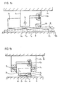
- a length measuring system is shown in two views, in which a scale 2 is attached to a bed 1 1 of a machine, not shown, for example by gluing, the division of which by a scanning unit 3 by means of a scanning plate 4 1 and not is scanned by means of an illumination device and by means of photo elements; the scanning unit 3 is connected to a driver 5 1 , which is rigidly attached to a carriage 6 1 of the machine.
- the scanner unit 3 1 is supported by a shaft 7 1 pivotably in the carrier 5.
- an error correction profile 8 1 is mounted on the bed 1 1, which is scanned by a shaft mounted in the scanner unit 3 1 roll 9 1 under the pressure of a spring 10 1, so that during the measuring process, the scanning unit 3 1 or Division plane 11 1 of the scanning plate 4 1 experiences rotations through a variable angle ⁇ 1 with respect to the division plane 12 1 of the scale 2 1 .
- the centerline of the axle 7 1 ⁇ a constant distance from the plane of division 12 1 of the scale 2 1 has 1, there is a measurement value correction of amount ⁇ 1 ⁇ 1 according to the error profile in the direction of measurement X.
- the axis 7 1 runs at a parallel distance a 1 from the parting plane 12 1 of the scale 2 1 parallel to the measuring direction X perpendicular to the measuring direction X.
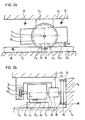
- a scale 2 2 is attached to a bed 1 2 of a machine, not shown, for example by gluing, the division of which by a scanning unit 3 z by means of a scanning plate 4 2 and in not shown is scanned by means of an illumination device and by means of photo elements; the scanning unit 3 2 is connected to a driver 5 2 , which is rigidly attached to a carriage 6 2 of the machine.
- the scanner unit 3 2 is supported by a shaft 7 2 pivotably in a bearing 13 of the follower 5 2 and connected to a reduction gear 14, which at Carrier 5 2 is attached.
- the reduction gear 14 is connected via a shaft 15 to an adjusting wheel 16, which has equidistant recesses 17 along its circumference, into which adjusting bolts 18 on the bed 1 2 engage at diametrically opposite locations when the scanning unit 3 2 moves, depending on the course of the error, in order to do this Rotate the adjusting wheel 16 forward or backward in each case by a cutout 17, so that the scanning unit 3 2 or the graduation plane 11 2 of the scanning plate 4 experiences 2 rotations by a variable angle ⁇ 2 with respect to the graduation plane 12 2 of the scale 2 2 .
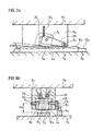
- 3a, b show a length measuring system in two views, in which a scale 2 3 is attached to a bed 1 3 of a machine (not shown ), for example by gluing, the division of which by a scanning unit 3 3 by means of an illumination device in the form of a lamp 21 and a condenser 22, a scanning plate 4 3 and scanned by means of photo elements 23; the scanning unit 3 3 is rigidly attached to a carriage 6 3 of the machine. While the lamp 21, the condenser 22 and the photo elements 23 are fixedly arranged in the scanning unit 3 3 , the scanning plate 4 3 in a carrier 24 is for error correction when measuring the relative position between the carriage 6 3 and the bed 1 3 of the machine an axis 7 3 pivotally mounted in the scanning unit 3 3 .
- an error correction profile 8 3 is fastened on the bed 13, which is scanned by a roller 9 3 under the pressure of a spring 10 3 ; the roller 9 3 is mounted on one end of a lever 25 which is rigidly connected to the shaft 7 3 at the other end.
- the graduation plane 11 3 of the scanning plate 4 3 experiences rotations by a variable angle ⁇ 3 with respect to the graduation plane 12 3 of the scale 2 3 according to the course of the error.
- the centerline of the axle 7 3 2 3 has a constant distance a 3 from the dividing plane 12 3 of the scale, there is a measurement value correction of amount ⁇ 3 ⁇ ⁇ 3 corresponding to the error profile in the direction of measurement X.
- the axis 7 3 extends in parallel spaced a 3 from the graduation plane 12 3 of the scale 2 3 parallel to the measuring direction X perpendicular to the measuring direction X.
- the pivot axis 7 is preferably in the plane of symmetry perpendicular to the scanning plate 4 perpendicular to the measuring direction X.
- the pivot axis of the scanning unit can also be formed, for example, by two guide rollers in order to guide the scanning unit on guide surfaces of the scale or of a housing for the scale.
- the invention is not limited to photoelectric measuring systems, but can also be used in optical, magnetic, inductive and capacitive measuring systems.
Landscapes
- Physics & Mathematics (AREA)
- General Physics & Mathematics (AREA)
- Length Measuring Devices With Unspecified Measuring Means (AREA)
- Optical Transform (AREA)
- Length Measuring Devices By Optical Means (AREA)
- Measurement Of Length, Angles, Or The Like Using Electric Or Magnetic Means (AREA)
- Length-Measuring Instruments Using Mechanical Means (AREA)
Priority Applications (1)
| Application Number | Priority Date | Filing Date | Title |
|---|---|---|---|
| AT83100745T ATE17039T1 (de) | 1982-03-25 | 1983-01-27 | Digitales elektrisches laengen- oder winkelmesssystem. |
Applications Claiming Priority (2)
| Application Number | Priority Date | Filing Date | Title |
|---|---|---|---|
| DE3210962 | 1982-03-25 | ||
| DE19823210962 DE3210962A1 (de) | 1982-03-25 | 1982-03-25 | Laengen- oder winkelmesssystem |
Publications (2)
| Publication Number | Publication Date |
|---|---|
| EP0090139A1 EP0090139A1 (de) | 1983-10-05 |
| EP0090139B1 true EP0090139B1 (de) | 1985-12-18 |
Family
ID=6159261
Family Applications (1)
| Application Number | Title | Priority Date | Filing Date |
|---|---|---|---|
| EP83100745A Expired EP0090139B1 (de) | 1982-03-25 | 1983-01-27 | Digitales elektrisches Längen- oder Winkelmesssystem |
Country Status (5)
| Country | Link |
|---|---|
| US (1) | US4475289A (enExample) |
| EP (1) | EP0090139B1 (enExample) |
| JP (1) | JPS58169026A (enExample) |
| AT (1) | ATE17039T1 (enExample) |
| DE (1) | DE3210962A1 (enExample) |
Families Citing this family (9)
| Publication number | Priority date | Publication date | Assignee | Title |
|---|---|---|---|---|
| DE3216616C2 (de) * | 1982-05-04 | 1985-06-27 | Dr. Johannes Heidenhain Gmbh, 8225 Traunreut | Elektrisches Längen- oder Winkelmeßsystem |
| AT395070B (de) * | 1983-11-22 | 1992-09-10 | Emr Elektronische Mess Und Reg | Laengenmesseinrichtung, insbesondere gekapselte laengenmesseinrichtung |
| AT379449B (de) * | 1984-07-03 | 1986-01-10 | R S F Elektronik Ohg Rechtsfor | Laengenmesseinrichtung |
| US4974332A (en) * | 1988-08-19 | 1990-12-04 | Delta International Machinery Corp. | Measurement system reader element standoff |
| AT394110B (de) * | 1989-02-10 | 1992-02-10 | Rsf Elektronik Gmbh | Laengenmesssystem |
| US7197828B2 (en) * | 2005-05-31 | 2007-04-03 | Asml Netherlands B.V. | Lithographic apparatus and device manufacturing method utilizing FPD chuck Z position measurement |
| DE102009026492A1 (de) * | 2009-05-27 | 2011-03-03 | Robert Bosch Gmbh | Handwerkzeug |
| DE102011007459B4 (de) | 2011-04-15 | 2023-05-11 | Dr. Johannes Heidenhain Gmbh | Optische Längenmesseinrichtung |
| ES2694043T3 (es) * | 2016-04-05 | 2018-12-17 | Dr. Johannes Heidenhain Gmbh | Dispositivo de medición de longitud |
Citations (1)
| Publication number | Priority date | Publication date | Assignee | Title |
|---|---|---|---|---|
| DE853657C (de) * | 1944-09-05 | 1952-10-27 | Leitz Ernst Gmbh | Vorrichtung zur Berichtigung der aus dem Geraet sich ergebenden Mess-fehler von mit optischen Messeinrichtungen versehenen Maschinen und Instrumenten |
Family Cites Families (7)
| Publication number | Priority date | Publication date | Assignee | Title |
|---|---|---|---|---|
| US226162A (en) * | 1880-04-06 | Island | ||
| DE2712422C2 (de) * | 1977-03-22 | 1978-11-09 | Dr. Johannes Heidenhain Gmbh, 8225 Traunreut | Längenmeßeinrichtung |
| DE2724858A1 (de) * | 1977-06-02 | 1978-12-07 | Heidenhain Gmbh Dr Johannes | Laengenmessgeraet mit korrektureinrichtung |
| DE2810341C2 (de) * | 1978-03-10 | 1980-01-31 | Dr. Johannes Heidenhain Gmbh, 8225 Traunreut | Längenmeßeinrichtung |
| DE2820753C2 (de) * | 1978-05-12 | 1980-03-06 | Dr. Johannes Heidenhain Gmbh, 8225 Traunreut | Einrichtung zur Fehlerkorrektur bei Positionsmeßsystemen |
| DE2844066C2 (de) * | 1978-10-10 | 1982-04-22 | Dr. Johannes Heidenhain Gmbh, 8225 Traunreut | Längen- oder Winkelmeßeinrichtung |
| DD142522B1 (de) * | 1978-11-14 | 1981-12-30 | Trepte Klaus Dieter | Einrichtung zur korrektur eines maschinengesamtfehlers |
-
1982
- 1982-03-25 DE DE19823210962 patent/DE3210962A1/de active Granted
-
1983
- 1983-01-27 EP EP83100745A patent/EP0090139B1/de not_active Expired
- 1983-01-27 AT AT83100745T patent/ATE17039T1/de not_active IP Right Cessation
- 1983-03-14 JP JP58040848A patent/JPS58169026A/ja active Pending
- 1983-03-18 US US06/476,529 patent/US4475289A/en not_active Expired - Fee Related
Patent Citations (1)
| Publication number | Priority date | Publication date | Assignee | Title |
|---|---|---|---|---|
| DE853657C (de) * | 1944-09-05 | 1952-10-27 | Leitz Ernst Gmbh | Vorrichtung zur Berichtigung der aus dem Geraet sich ergebenden Mess-fehler von mit optischen Messeinrichtungen versehenen Maschinen und Instrumenten |
Also Published As
| Publication number | Publication date |
|---|---|
| ATE17039T1 (de) | 1986-01-15 |
| US4475289A (en) | 1984-10-09 |
| JPS58169026A (ja) | 1983-10-05 |
| EP0090139A1 (de) | 1983-10-05 |
| DE3210962C2 (enExample) | 1987-10-01 |
| DE3210962A1 (de) | 1983-10-20 |
Similar Documents
| Publication | Publication Date | Title |
|---|---|---|
| EP0090139B1 (de) | Digitales elektrisches Längen- oder Winkelmesssystem | |
| DE3146107C2 (enExample) | ||
| DE2820753C2 (de) | Einrichtung zur Fehlerkorrektur bei Positionsmeßsystemen | |
| DE19527809C2 (de) | Vorrichtung zum Prüfen der Radausrichtung | |
| EP0521254B2 (de) | Radstellungsmessgerät | |
| DE3118607C2 (de) | Längenmeßgerät | |
| DE2427407B2 (de) | Vorrichtung fuer statische und dynamische versuche an fahrzeugreifen | |
| DE2724858C3 (enExample) | ||
| EP0678353A1 (de) | Verfahren und Einrichtung zum Fixieren von Radsätzen von Schienenfahrzeugen im Rotationszentrum | |
| EP0084624A2 (de) | Längenmesseinrichtung | |
| DE3206875C2 (de) | Winkelmeßeinrichtung | |
| US3987688A (en) | Adjustable control cam | |
| EP0123018B1 (de) | Messsystem mit einer Einrichtung zur Fehlerkorrektur | |
| DE2432856B2 (de) | Vorrichtung zum profilieren einer schleifscheibe mittels eines diamanten | |
| US6699103B1 (en) | Mower reel blade grinding device | |
| DE102022108742B4 (de) | Messvorrichtung | |
| DE69608088T2 (de) | Selbsteinstellende schwenkbare Halterung für eine Rohrbiegemaschine | |
| DE69403235T2 (de) | System zum Messen des Radstands eines Kraftfahrzeugrahmens und des Quer- und Längsversatzes seiner lenkbaren Räder | |
| WO1999038689A1 (de) | Verfahren zur ermittlung einer drehwinkellage eines ortsveränderbaren zylinders einer druckmaschine | |
| EP0075081A1 (de) | Fehlerkompensationseinrichtung für Präzisionsmaschinen und Messgeräte | |
| DE102010042123B3 (de) | Anordnung mit einem drehbaren Röntgendetektor | |
| DE3020468A1 (de) | Anordnung zur kompensation des horzontalen winkelfehlers eines tonarms | |
| DE4316599C2 (de) | Getriebeanordnung | |
| DE2421365C3 (de) | Meßeinrichtung mit einem Reibrad-Präzisionsmeßgerät | |
| DE2924743A1 (de) | Vorrichtung zum ueberpruefen der parallelitaet bzw. spur von fahrzeugraedern |
Legal Events
| Date | Code | Title | Description |
|---|---|---|---|
| PUAI | Public reference made under article 153(3) epc to a published international application that has entered the european phase |
Free format text: ORIGINAL CODE: 0009012 |
|
| 17P | Request for examination filed |
Effective date: 19830203 |
|
| AK | Designated contracting states |
Designated state(s): AT CH FR GB IT LI NL SE |
|
| ITF | It: translation for a ep patent filed | ||
| GRAA | (expected) grant |
Free format text: ORIGINAL CODE: 0009210 |
|
| AK | Designated contracting states |
Designated state(s): AT CH FR GB IT LI NL SE |
|
| REF | Corresponds to: |
Ref document number: 17039 Country of ref document: AT Date of ref document: 19860115 Kind code of ref document: T |
|
| ET | Fr: translation filed | ||
| PLBE | No opposition filed within time limit |
Free format text: ORIGINAL CODE: 0009261 |
|
| STAA | Information on the status of an ep patent application or granted ep patent |
Free format text: STATUS: NO OPPOSITION FILED WITHIN TIME LIMIT |
|
| 26N | No opposition filed | ||
| ITTA | It: last paid annual fee | ||
| PGFP | Annual fee paid to national office [announced via postgrant information from national office to epo] |
Ref country code: FR Payment date: 19901217 Year of fee payment: 9 Ref country code: GB Payment date: 19901217 Year of fee payment: 9 |
|
| PGFP | Annual fee paid to national office [announced via postgrant information from national office to epo] |
Ref country code: CH Payment date: 19901227 Year of fee payment: 9 Ref country code: SE Payment date: 19901227 Year of fee payment: 9 |
|
| PGFP | Annual fee paid to national office [announced via postgrant information from national office to epo] |
Ref country code: AT Payment date: 19901228 Year of fee payment: 9 |
|
| PGFP | Annual fee paid to national office [announced via postgrant information from national office to epo] |
Ref country code: NL Payment date: 19910131 Year of fee payment: 9 |
|
| PG25 | Lapsed in a contracting state [announced via postgrant information from national office to epo] |
Ref country code: GB Effective date: 19920127 Ref country code: AT Effective date: 19920127 |
|
| PG25 | Lapsed in a contracting state [announced via postgrant information from national office to epo] |
Ref country code: SE Effective date: 19920128 |
|
| PG25 | Lapsed in a contracting state [announced via postgrant information from national office to epo] |
Ref country code: CH Effective date: 19920131 Ref country code: LI Effective date: 19920131 |
|
| PG25 | Lapsed in a contracting state [announced via postgrant information from national office to epo] |
Ref country code: NL Effective date: 19920801 |
|
| NLV4 | Nl: lapsed or anulled due to non-payment of the annual fee | ||
| GBPC | Gb: european patent ceased through non-payment of renewal fee | ||
| PG25 | Lapsed in a contracting state [announced via postgrant information from national office to epo] |
Ref country code: FR Effective date: 19920930 |
|
| REG | Reference to a national code |
Ref country code: CH Ref legal event code: PL |
|
| REG | Reference to a national code |
Ref country code: FR Ref legal event code: ST |
|
| EUG | Se: european patent has lapsed |
Ref document number: 83100745.5 Effective date: 19920806 |