EP0089942B1 - Rifle breech block - Google Patents
Rifle breech block Download PDFInfo
- Publication number
- EP0089942B1 EP0089942B1 EP83890001A EP83890001A EP0089942B1 EP 0089942 B1 EP0089942 B1 EP 0089942B1 EP 83890001 A EP83890001 A EP 83890001A EP 83890001 A EP83890001 A EP 83890001A EP 0089942 B1 EP0089942 B1 EP 0089942B1
- Authority
- EP
- European Patent Office
- Prior art keywords
- extractor
- cartridge
- bolt
- recess
- claw
- Prior art date
- Legal status (The legal status is an assumption and is not a legal conclusion. Google has not performed a legal analysis and makes no representation as to the accuracy of the status listed.)
- Expired
Links
Images
Classifications
-
- F—MECHANICAL ENGINEERING; LIGHTING; HEATING; WEAPONS; BLASTING
- F41—WEAPONS
- F41A—FUNCTIONAL FEATURES OR DETAILS COMMON TO BOTH SMALLARMS AND ORDNANCE, e.g. CANNONS; MOUNTINGS FOR SMALLARMS OR ORDNANCE
- F41A15/00—Cartridge extractors, i.e. devices for pulling cartridges or cartridge cases at least partially out of the cartridge chamber; Cartridge ejectors, i.e. devices for throwing the extracted cartridges or cartridge cases free of the gun
- F41A15/12—Cartridge extractors, i.e. devices for pulling cartridges or cartridge cases at least partially out of the cartridge chamber; Cartridge ejectors, i.e. devices for throwing the extracted cartridges or cartridge cases free of the gun for bolt-action guns
- F41A15/14—Cartridge extractors, i.e. devices for pulling cartridges or cartridge cases at least partially out of the cartridge chamber; Cartridge ejectors, i.e. devices for throwing the extracted cartridges or cartridge cases free of the gun for bolt-action guns the ejector being mounted on or within the bolt; Extractors per se
Definitions
- the invention relates to a rifle lock or the like.
- the barrel is inserted from one side and the locking piece can be inserted from the other side, the locking piece carrying locking lugs at its front end and the housing having grooves corresponding to the locking lugs, which open into a rotation limited by the end, which allows the locking piece to be rotated, and wherein the locking piece is provided with a resiliently pivotable cartridge extractor which lies between two locking lugs and ends in a claw.
- Such a rifle lock is e.g. known from GB-A-2 060 144. If the rifle barrel is blocked by some foreign body and a shot is fired, the pressure of the powder gases, which rises far above the permissible value, can cause the cartridge case, which is usually made of brass, to tear. Although the cartridge case is firmly encased in the cartridge chamber of the barrel, its rear end, which has a groove for engaging the extractor claw, projects beyond the barrel end into the recess of the housing.
- the rear end of the cartridge protrudes into the breech block as far as the butt plate, but this frame has an interruption due to the breech block in the area of the extractor claw, the resiliently pivotable extractor claw not being able to withstand the increased gas pressure because it has play in the recess.
- the diameter of the recess is in fact chosen so that the extractor can carry out the swiveling movement required to reach over the cartridge bottom until the claw engages in the cartridge groove, regardless of the respective rotational position of the closure piece. If the cartridge case tears in the area of the extractor claw, neighboring gun parts are also destroyed or blown off by the powder gases escaping, so that the shooter is at maximum risk of injury. In addition, such damage to the weapon can result that it can no longer be used.
- the invention is therefore based on the object of eliminating these deficiencies and of creating a rifle lock of the type described at the outset, in which the risk of injury to the shooter or destruction of the weapon is eliminated by simple means in the event of barrel barrage.
- the invention achieves the stated object in that the inner wall of the housing forms a surface for the radial support of the extractor claw when the closure piece is locked in the region of the recess, and a recess that allows the extractor to pivot is arranged in the circumferential direction next to this support surface.
- the extractor claw Since the extractor claw is supported radially when the closure piece is locked, it can no longer yield and forms the previously missing part of the rear end of the cartridge closing frame through the closure piece. Tearing of the cartridge case in the previously endangered area is thus prevented with certainty. Nevertheless, the extractor can fully fulfill its function, since when it is rotated out of the locking position in the recess provided next to the support surface, it has enough play to perform the required pivoting movement. This does not result in an increase in the manufacturing effort required, since it is only a question of shaping the recess accordingly.
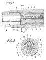
- the barrel 2 is screwed into a housing 1 connected to the rifle stock (not shown) from one side (from the left according to FIG. 1) and the locking piece 3 is inserted from the other side.
- the closure piece 3 has locking lugs 4 at its front end, and the housing is provided with longitudinal grooves 5 corresponding to these lugs 4 (FIG. 2).
- the warts 4 pass through the grooves 5, which open into a recess 6, so that the closure piece can be rotated for locking purposes when the warts 4 pass through the grooves 5 and have reached the recess 6.
- the locked position of the closure piece 3 is shown.
- the closure piece 3 is provided with a resiliently pivotable cartridge extractor 7, which lies between two locking lugs 4 and ends in an extractor claw 7.
- the cartridge case 9 lying in the cartridge chamber of the barrel 2 protrudes somewhat towards the rear over the barrel end and has an annular groove 10 into which the extractor claw 8 can engage.
- the inner wall of the housing 1 forms in the region of the recess 6 a surface 11 for the radial support of the extractor claw 8 when the closure piece 3 is locked. From FIG. 2 it can be seen that a recess 12 which allows the extractor to pivot is arranged next to the support surface 11. For manufacturing reasons, the recess 12 corresponds to the longitudinal grooves 5 for the locking lugs 4.
Description
Die Erfindung betrifft einen Gewehrverschluss mit einem Gehäuse od.dgl., in dem von der einen Seite der Lauf eingesetzt und von der anderen Seite das Verschlussstück einschiebbar ist, wobei das Verschlussstück an seinem Vorderende Verriegelungswarzen trägt und das Gehäuse den Verriegelungswarzen entsprechende Nuten aufweist, die in eine vom Laufende begrenzte, das Verdrehen des Verschlussstückes ermöglichende Ausdrehung münden, und wobei das Verschlussstück mit einem zwischen zwei Verriegelungswarzen liegenden, in einer Kralle endenden, federnd schwenkbaren Patronenauszieher versehen ist.The invention relates to a rifle lock or the like. In which the barrel is inserted from one side and the locking piece can be inserted from the other side, the locking piece carrying locking lugs at its front end and the housing having grooves corresponding to the locking lugs, which open into a rotation limited by the end, which allows the locking piece to be rotated, and wherein the locking piece is provided with a resiliently pivotable cartridge extractor which lies between two locking lugs and ends in a claw.
Ein solcher Gewehrverschluss ist z.B. aus der GB-A-2 060 144 bekannt. Ist dabei der Gewehrlauf durch irgendeinen Fremdkörper verdämmt und wird dann ein Schuss abgegeben, so kann es durch den weit über den zulässigen Wert ansteigenden Druck der Pulvergase zu einem Reissen der in der Regel aus Messing bestehenden Patronenhülse kommen. Zwar ist die Patronenhülse im Patronenlager des Laufes fest umfasst, doch steht sie mit ihrem Hinterende, das zum Eingreifen der Auszieherkralle eine Rille aufweist, über das Laufende in die Ausdrehung des Gehäuses vor. Innerhalb der Ausdrehung ragt das Patronenhinterende bis zum Stossboden in das Verschlussstück ein, doch weist diese Umrahmung durch das Verschlussstück im Bereich der Auszieherkralle eine Unterbrechung auf, wobei die federnd schwenkbare Auszieherkralle dem erhöhten Gasdruck keinesfalls standhalten kann, weil sie in der Ausdrehung Bewegungsspiel hat. Der Durchmesser der Ausdrehung ist nämlich so gewählt, dass der Auszieher die zum Übergreifen des Patronenbodens bis zum Einrasten der Kralle in die Patronenrille erforderliche Schwenkbewegung unabhängig von der jeweiligen Drehstellung des Verschlussstückes durchführen kann. Kommt es zu einem Reissen der Patronenhülse im Bereich der Auszieherkralle, so werden durch die austretenden Pulvergase auch benachbarte Waffenteile zerstört bzw. abgesprengt, so dass höchste Verletzungsgefahr für den Schützen besteht. Darüber hinaus können sich solche Beschädigungen der Waffe ergeben, dass sie nicht mehr weiter verwendbar ist.Such a rifle lock is e.g. known from GB-A-2 060 144. If the rifle barrel is blocked by some foreign body and a shot is fired, the pressure of the powder gases, which rises far above the permissible value, can cause the cartridge case, which is usually made of brass, to tear. Although the cartridge case is firmly encased in the cartridge chamber of the barrel, its rear end, which has a groove for engaging the extractor claw, projects beyond the barrel end into the recess of the housing. Within the recess, the rear end of the cartridge protrudes into the breech block as far as the butt plate, but this frame has an interruption due to the breech block in the area of the extractor claw, the resiliently pivotable extractor claw not being able to withstand the increased gas pressure because it has play in the recess. The diameter of the recess is in fact chosen so that the extractor can carry out the swiveling movement required to reach over the cartridge bottom until the claw engages in the cartridge groove, regardless of the respective rotational position of the closure piece. If the cartridge case tears in the area of the extractor claw, neighboring gun parts are also destroyed or blown off by the powder gases escaping, so that the shooter is at maximum risk of injury. In addition, such damage to the weapon can result that it can no longer be used.
Bei einem anderen bekannten Gewehrverschluss dieser Art (GB-A-2 024 383) wird mit Hilfe von Anlaufflächen am Patronenauszieher einerseits und am Verschlussgehäuse andererseits die Auszieherkralle beim Ausziehvorgang daran gehindert, dass sie den hinteren Patronenrand überspringt. Dadurch wird aber die Sicherheit des Schützen bei einem etwaigen Schuss mit verdämmtem Lauf deshalb nicht verbessert, weil die durch die Anlaufflächen erzielte Abstützung für den Patronenauszieher nicht in unmittelbarer Nähe des Patronenbodens erfolgt. Die Auszieherkralle kann daher schon bei geringem radialem Druck nach aussen nachgeben und demnach ein Aufreissen des Patronenbodens nicht verhindern. Die Abstützung des Patronenausziehers erfolgt erst dann, wenn der Verschluss entriegelt wird, so dass im massgeblichen Zeitpunkt bei der Schussabgabe keine Abstützung vorhanden ist.In another known rifle closure of this type (GB-A-2 024 383), with the help of contact surfaces on the cartridge extractor on the one hand and on the breech housing on the other hand, the extractor claw is prevented from jumping over the rear cartridge rim during the extraction process. However, this does not improve the safety of the shooter in the event of a shot with a barred barrel because the support for the cartridge extractor achieved by the contact surfaces is not in the immediate vicinity of the cartridge base. The extractor claw can therefore yield to the outside even at low radial pressure and therefore cannot prevent the cartridge base from tearing open. The cartridge extractor is only supported when the bolt is unlocked, so that there is no support at the relevant time when the shot is fired.
Es ist zwar auch schon bekannt, dem Patronenauszieher in der Verriegelungsstellung des Verschlusses eine feste Stütze zu geben (US-A-3 253 362), wobei es sich aber um eine andere Konstruktion mit dem Vorderende des Verschlussstückes rückversetzten Verriegelungswarzen handelt und die Funktionssicherheit nicht gewährleistet ist. Es ist nämlich für das Eingreifen der Auszieherkralle in die Rille der Patrone Voraussetzung, dass die Patrone an der der Auszieherkralle diametral gegenüberliegenden Seite bereits formschlüssig in die entsprechende Hinterschneidung des Verschlussstückes eingerastet ist, was nur beim händischen Einführen der Patrone möglich ist, weil ein an der Stirnseite des Verschlussstückes angeordneter, gefederter Ausstosser die aus einem Magazin aufsteigende Patrone darin hindern würde, in die richtige Lage in der Hinterschneidung einzutreten. Hat aber die Patrone von vornherein nicht die richtige Lage an der Stirnfläche des Verschlussstückes, so kann die Auszieherkralle in die Rille der Patrone überhaupt nicht eingreifen.It is also known to give the cartridge extractor a firm support in the locking position of the breech (US Pat. No. 3,253,362), but this is a different construction with locking lugs set back with the front end of the breech piece and does not guarantee functional reliability is. It is namely a prerequisite for the engagement of the extractor claw in the groove of the cartridge that the cartridge on the diametrically opposite side of the extractor claw is already positively engaged in the corresponding undercut of the closure piece, which is only possible when the cartridge is inserted by hand because one on the Spring-loaded ejector arranged on the front side of the closure piece would prevent the cartridge rising from a magazine from entering the correct position in the undercut. However, if the cartridge is not in the correct position on the end face of the closure piece from the start, the extractor claw cannot engage in the groove of the cartridge at all.
Schliesslich ist es bekannt, zur Verhinderung von Ausziehstörungen im Gehäuse eine zusätzliche Einrichtung vorzusehen, die die Auszieherkralle beim Öffnen des Verschlusses fest im Eingriff mit dem Patronenrand hält (DE-C-277 213). Diese Einrichtung ergibt zwar eine Abstützung für den Patronenauszieher in der Verriegelungsstellung, ist aber für Drehverschlüsse unbrauchbar, weil sich der Patronenauszieher beim drehenden Verriegeln aus dem Wirkungsbereich dieser Einrichtung wegbewegen würde. Ausserdem ist die bekannte Einrichtung nur dann wirksam, wenn eine Druckfeder einen Riegel nach jedem Ladevorgang wieder zuverlässig in die Funktionsstellung zurückbringt. Bei stärkerer Verschmutzung oder Vereisung im Bereich der Riegellagerung ist die Rückbewegung durch die Druckfeder aber keineswegs gesichert. Ausserdem handelt es sich um eine zusätzliche Konstruktion aus kleinen, störanfälligen Teilen.Finally, it is known to provide an additional device in the housing to prevent pull-out disturbances, which holds the pull-out claw firmly in engagement with the cartridge rim when the breech is opened (DE-C-277 213). Although this device provides support for the cartridge extractor in the locking position, it is unusable for rotary locks because the cartridge extractor would move away from the area of action of this device when rotating locking. In addition, the known device is only effective if a compression spring reliably brings a bolt back into the functional position after each loading process. In the event of heavy soiling or icing in the area of the transom bearing, the return movement is by no means secured by the compression spring. In addition, it is an additional construction made of small, susceptible parts.
Demnach liegt der Erfindung die Aufgabe zugrunde, diese Mängel zu beseitigen und einen Gewehrverschluss der eingangs geschilderten Art zu schaffen, bei dem die Gefahr der Verletzung des Schützen bzw. der Zerstörung der Waffe bei einer Laufverdämmung mit einfachen Mitteln beseitigt ist.The invention is therefore based on the object of eliminating these deficiencies and of creating a rifle lock of the type described at the outset, in which the risk of injury to the shooter or destruction of the weapon is eliminated by simple means in the event of barrel barrage.
Die Erfindung löst die gestellte Aufgabe dadurch, dass die Gehäuseinnenwand im Bereich der Ausdrehung eine Fläche zur radialen Abstützung der Auszieherkralle bei verriegeltem Verschlussstück bildet und in Umfangsrichtung neben dieser Stützfläche eine das Verschwenken des Ausziehers ermöglichende Ausnehmung angeordnet ist.The invention achieves the stated object in that the inner wall of the housing forms a surface for the radial support of the extractor claw when the closure piece is locked in the region of the recess, and a recess that allows the extractor to pivot is arranged in the circumferential direction next to this support surface.
Da also die Auszieherkralle bei verriegeltem Verschlussstück radial abgestützt ist, kann sie nicht mehr nachgeben und bildet den bisher fehlenden Teil der das Patronenhinterende einschliessende Umrahmung durch das Verschlussstück. Es wird also ein Reissen der Patronenhülse in dem bisher gefährdeten Bereich mit Sicherheit verhindert. Dennoch kann der Auszieher seine Funktion voll erfüllen, da er bei aus der Verriegelungsstellung verdrehter Lage in der neben der Stützfläche vorgesehenen Ausnehmung genügend Bewegungsspiel hat, um die erforderliche Schwenkbewegung auszuführen. Dabei ergibt sich keine Erhöhung des notwendigen Herstellungsaufwandes, da es ja nur darum geht, die Ausdrehung entsprechend zu formen.Since the extractor claw is supported radially when the closure piece is locked, it can no longer yield and forms the previously missing part of the rear end of the cartridge closing frame through the closure piece. Tearing of the cartridge case in the previously endangered area is thus prevented with certainty. Nevertheless, the extractor can fully fulfill its function, since when it is rotated out of the locking position in the recess provided next to the support surface, it has enough play to perform the required pivoting movement. This does not result in an increase in the manufacturing effort required, since it is only a question of shaping the recess accordingly.
In der Zeichnung ist der Erfindungsgegenstand in einem Ausführungsbeispiel dargestellt, und zwar zeigen
- Fig. 1 die wesentlichen Teile eines Gewehrverschlusses im Axialschnitt und
- Fig. 2 im Querschnitt nach der Linie 11-11 der Fig. 1 bei verriegeltem Verschlussstück.
- Fig. 1 shows the essential parts of a rifle slide in axial section
- Fig. 2 in cross section along the line 11-11 of Fig. 1 with the locking piece locked.
In einem mit dem nicht dargestellten Gewehrschaft verbundenen Gehäuse 1 ist von der einen Seite (von links gemäss Fig. 1) der Lauf 2 eingeschraubt und von der anderen Seite das Verschlussstück 3 eingeschoben. Das Verschlussstück 3 weist an seinem Vorderende Verriegelungswarzen 4 auf, und das Gehäuse ist mit diesen Warzen 4 entsprechenden Längsnuten 5 (Fig. 2) versehen. Beim Einschieben des Verschlussstückes 3 in das Gehäuse 1 durchlaufen die Warzen 4 die Nuten 5, die in eine Ausdrehung 6 münden, so dass das Verschlussstück zur Verriegelung verdreht werden kann, wenn die Warzen 4 die Nuten 5 durchlaufen und die Ausdrehung 6 erreicht haben. In der Zeichnung ist die verriegelte Stellung des Verschlussstückes 3 dargestellt.The barrel 2 is screwed into a
Das Verschlussstück 3 ist mit einem federnd schwenkbaren Patronenauszieher 7 versehen, der zwischen zwei Verriegelungswarzen 4 liegt und in einer Auszieherkralle 7 endet. Die im Patronenlager des Laufes 2 liegende Patronenhülse 9 ragt über das Laufende etwas nach hinten vor und besitzt eine Ringrille 10, in die die Auszieherkralle 8 eingreifen kann.The
Die Innenwand des Gehäuses 1 bildet im Bereich der Ausdrehung 6 eine Fläche 11 zur radialen Abstützung der Auszieherkralle 8 bei verriegeltem Verschlussstück 3. Aus Fig. 2 ist ersichtlich, dass neben der Stützfläche 11 eine das Verschwenken des Ausziehers ermöglichende Ausnehmung 12 angeordnet ist. Aus fertigungstechnischen Gründen entspricht die Ausnehmung 12 den Längsnuten 5 für die Verriegelungswarzen 4.The inner wall of the
Claims (1)
- A rifle breech block comprising a housing (1) or the like, into which the barrel (2) is inserted from one end and the bolt (3) is adapted to be slidably inserted from the opposite end, wherein the bolt (3) carries locking bosses (4) at its forward end and the housing (1) is provided with grooves (5), which correspond to the locking bosses (4) and open into a turned recess (6), which is defined by the end of the barrel and permits the bolt (3) to be rotated, and the bolt (3) is provided with an extractor (7), which is disposed between two locking bosses (4) and terminates in a claw (8) and is pivotally movable against a spring bias, characterized in that the inside surface of the housing constitutes adjacent to the turned recess (6) a surface (11) for radially supporting the extractor claw (8) when the bolt (3) is locked, and a recess (12) which permits a pivotal movement of the extractor (7) is disposed beside that supporting surface (11) in the peripheral direction.
Applications Claiming Priority (2)
| Application Number | Priority Date | Filing Date | Title |
|---|---|---|---|
| AT1143/82 | 1982-03-24 | ||
| AT0114382A AT372781B (en) | 1982-03-24 | 1982-03-24 | RIFLE Breech |
Publications (3)
| Publication Number | Publication Date |
|---|---|
| EP0089942A2 EP0089942A2 (en) | 1983-09-28 |
| EP0089942A3 EP0089942A3 (en) | 1984-09-12 |
| EP0089942B1 true EP0089942B1 (en) | 1986-06-04 |
Family
ID=3507531
Family Applications (1)
| Application Number | Title | Priority Date | Filing Date |
|---|---|---|---|
| EP83890001A Expired EP0089942B1 (en) | 1982-03-24 | 1983-01-07 | Rifle breech block |
Country Status (7)
| Country | Link |
|---|---|
| US (1) | US4555860A (en) |
| EP (1) | EP0089942B1 (en) |
| AT (1) | AT372781B (en) |
| BR (1) | BR8301496A (en) |
| DE (1) | DE3363838D1 (en) |
| ES (1) | ES280973Y (en) |
| FI (1) | FI71991C (en) |
Families Citing this family (13)
| Publication number | Priority date | Publication date | Assignee | Title |
|---|---|---|---|---|
| US4653210A (en) * | 1985-02-28 | 1987-03-31 | Poff Jr Charles R | Firearm bolt action and extractor |
| US4930238A (en) * | 1988-04-21 | 1990-06-05 | Poff Jr Charles R | Rimfire firearm receiver |
| US5911173A (en) * | 1996-10-18 | 1999-06-08 | Westrom; Mark A. | Breech bolt assembly for a firearm |
| DE19843294C2 (en) * | 1998-09-22 | 2001-10-04 | Rheinmetall W & M Gmbh | Large-caliber barrel weapon with a catch and ejection device arranged longitudinally on the base |
| IL160803A (en) * | 2004-03-10 | 2010-06-16 | Israel Weapon Ind I W I Ltd | Safety mechanism for a rifle |
| US8087194B1 (en) * | 2009-03-24 | 2012-01-03 | Sturm, Ruger & Company, Inc. | Firearm barrel retaining system |
| US9057576B2 (en) | 2009-03-24 | 2015-06-16 | Sturm, Ruger & Company, Inc. | Firearm with quick coupling barrel system |
| US8505227B2 (en) * | 2009-03-24 | 2013-08-13 | Sturm, Ruger & Company, Inc. | Firearm with quick coupling barrel interlock system |
| US8490312B2 (en) * | 2009-03-24 | 2013-07-23 | Sturm, Ruger & Company, Inc. | Quick coupling barrel system for firearm |
| US8479429B2 (en) * | 2009-03-24 | 2013-07-09 | Sturm, Ruger & Company, Inc. | Firearm with quick coupling barrel system |
| WO2012142406A2 (en) * | 2011-04-14 | 2012-10-18 | Colt Defense, Llc | Improved extractor and bolt for a firearm |
| US8887427B2 (en) * | 2013-01-15 | 2014-11-18 | Smith & Wesson Corp. | Extractor for self-loading firearm |
| US9341436B2 (en) | 2014-08-13 | 2016-05-17 | Kenneth A Frankel | Gun assembly including gun action mated to gunstock by at least three zones of intentional interference fit |
Family Cites Families (8)
| Publication number | Priority date | Publication date | Assignee | Title |
|---|---|---|---|---|
| GB191200084A (en) * | 1912-01-01 | 1912-04-18 | Charles William Laird | Improvements in Extractors for Fire Arms. |
| GB191402315A (en) * | 1914-01-28 | 1915-01-28 | Grant Hammond | Improvements in Firearms. |
| US2807902A (en) * | 1954-04-16 | 1957-10-01 | Olin Mathieson | Cartridge extractors |
| US3027672A (en) * | 1961-04-26 | 1962-04-03 | George C Sullivan | Firearm with aluminum alloy receiver |
| US3253362A (en) * | 1964-04-21 | 1966-05-31 | Wilbur C Gitchell | Bolt actions for rifles |
| US3848351A (en) * | 1973-07-23 | 1974-11-19 | Gen Electric | Gun bolt |
| GB2024383B (en) * | 1977-12-05 | 1982-04-21 | Sterling Armament Co Ltd | Extractor mechanism |
| AU533255B2 (en) * | 1979-09-11 | 1983-11-10 | Commonwealth Of Australia, The | Firearm |
-
1982
- 1982-03-24 AT AT0114382A patent/AT372781B/en not_active IP Right Cessation
- 1982-12-20 US US06/451,042 patent/US4555860A/en not_active Expired - Lifetime
- 1982-12-27 FI FI824470A patent/FI71991C/en not_active IP Right Cessation
-
1983
- 1983-01-07 DE DE8383890001T patent/DE3363838D1/en not_active Expired
- 1983-01-07 EP EP83890001A patent/EP0089942B1/en not_active Expired
- 1983-03-23 ES ES1983280973U patent/ES280973Y/en not_active Expired
- 1983-03-23 BR BR8301496A patent/BR8301496A/en not_active IP Right Cessation
Also Published As
| Publication number | Publication date |
|---|---|
| FI824470L (en) | 1983-09-25 |
| FI71991C (en) | 1987-03-09 |
| US4555860A (en) | 1985-12-03 |
| ES280973U (en) | 1985-01-16 |
| DE3363838D1 (en) | 1986-07-10 |
| ES280973Y (en) | 1985-08-01 |
| BR8301496A (en) | 1983-12-06 |
| EP0089942A2 (en) | 1983-09-28 |
| FI71991B (en) | 1986-11-28 |
| AT372781B (en) | 1983-11-10 |
| EP0089942A3 (en) | 1984-09-12 |
| ATA114382A (en) | 1982-12-15 |
| FI824470A0 (en) | 1982-12-27 |
Similar Documents
| Publication | Publication Date | Title |
|---|---|---|
| EP0089942B1 (en) | Rifle breech block | |
| EP1518086B1 (en) | Machine gun | |
| DE10055578B4 (en) | Lock mechanism for rifles | |
| DE3339745C2 (en) | Adaptation cartridge for insert pipe system | |
| EP1596151A1 (en) | Semi-automatic gun | |
| EP0188681A1 (en) | Device for locking a breech bolt head in the rear part of a gun barrel | |
| DE2813633C2 (en) | Handgun with swiveling breech block | |
| EP0869326B1 (en) | Breech bolt locking for portable firearm | |
| DE7611322U1 (en) | FRONT LOADER HANDGUN | |
| DE2250650A1 (en) | SAFETY DEVICE FOR FIRE ARMS | |
| AT391943B (en) | Handguns, especially rifles | |
| EP0148984B1 (en) | Small arm with radially bored-through barrel and detachable silencer | |
| DE378352C (en) | Multi-stage machine gun driven by a hand crank | |
| AT396299B (en) | HANDGUN, ESPECIALLY HUNTING GUN | |
| DE19903326C1 (en) | Mechanism to open protective dust flaps at automatic weapon cartridge ejection systems has a direction setting to open the relevant dust flap on firing according to the selected direction of ejection | |
| DE2857888C2 (en) | Handgun with swiveling breech block | |
| EP0428525B1 (en) | Firearm | |
| EP0510253B1 (en) | Auxiliary loading device for the manual ramming of ammunition | |
| DE105618C (en) | ||
| EP0240845A1 (en) | Device for radially securing a cartridge during the loading by the breech-block into the cartridge chamber of an artillery gun | |
| EP0234287B1 (en) | Device for locking the barrels on a multibarrel gun | |
| DE3820943C1 (en) | Shooting weapon | |
| DE579195C (en) | Hinge for alarm guns and stun guns | |
| DE308556C (en) | ||
| DE1603732C (en) | Interception device for destroying the excess driving energy of the thrust piston on an internal combustion bolt setter |
Legal Events
| Date | Code | Title | Description |
|---|---|---|---|
| PUAI | Public reference made under article 153(3) epc to a published international application that has entered the european phase |
Free format text: ORIGINAL CODE: 0009012 |
|
| AK | Designated contracting states |
Designated state(s): BE CH DE FR GB IT LI SE |
|
| PUAL | Search report despatched |
Free format text: ORIGINAL CODE: 0009013 |
|
| AK | Designated contracting states |
Designated state(s): BE CH DE FR GB IT LI SE |
|
| 17P | Request for examination filed |
Effective date: 19841009 |
|
| GRAA | (expected) grant |
Free format text: ORIGINAL CODE: 0009210 |
|
| AK | Designated contracting states |
Kind code of ref document: B1 Designated state(s): BE CH DE FR GB IT LI SE |
|
| ITF | It: translation for a ep patent filed |
Owner name: STUDIO INGG. FISCHETTI & WEBER |
|
| REF | Corresponds to: |
Ref document number: 3363838 Country of ref document: DE Date of ref document: 19860710 |
|
| ET | Fr: translation filed | ||
| PLBE | No opposition filed within time limit |
Free format text: ORIGINAL CODE: 0009261 |
|
| STAA | Information on the status of an ep patent application or granted ep patent |
Free format text: STATUS: NO OPPOSITION FILED WITHIN TIME LIMIT |
|
| 26N | No opposition filed | ||
| ITTA | It: last paid annual fee | ||
| EAL | Se: european patent in force in sweden |
Ref document number: 83890001.7 |
|
| PGFP | Annual fee paid to national office [announced via postgrant information from national office to epo] |
Ref country code: GB Payment date: 19971211 Year of fee payment: 16 |
|
| PGFP | Annual fee paid to national office [announced via postgrant information from national office to epo] |
Ref country code: SE Payment date: 19971217 Year of fee payment: 16 |
|
| PGFP | Annual fee paid to national office [announced via postgrant information from national office to epo] |
Ref country code: FR Payment date: 19971231 Year of fee payment: 16 |
|
| PGFP | Annual fee paid to national office [announced via postgrant information from national office to epo] |
Ref country code: DE Payment date: 19980107 Year of fee payment: 16 Ref country code: CH Payment date: 19980107 Year of fee payment: 16 |
|
| PGFP | Annual fee paid to national office [announced via postgrant information from national office to epo] |
Ref country code: BE Payment date: 19980108 Year of fee payment: 16 |
|
| PG25 | Lapsed in a contracting state [announced via postgrant information from national office to epo] |
Ref country code: GB Free format text: LAPSE BECAUSE OF NON-PAYMENT OF DUE FEES Effective date: 19990107 |
|
| PG25 | Lapsed in a contracting state [announced via postgrant information from national office to epo] |
Ref country code: SE Free format text: LAPSE BECAUSE OF NON-PAYMENT OF DUE FEES Effective date: 19990108 |
|
| PG25 | Lapsed in a contracting state [announced via postgrant information from national office to epo] |
Ref country code: LI Free format text: LAPSE BECAUSE OF NON-PAYMENT OF DUE FEES Effective date: 19990131 Ref country code: CH Free format text: LAPSE BECAUSE OF NON-PAYMENT OF DUE FEES Effective date: 19990131 Ref country code: BE Free format text: LAPSE BECAUSE OF NON-PAYMENT OF DUE FEES Effective date: 19990131 |
|
| BERE | Be: lapsed |
Owner name: STEYR-DAIMLER-PUCH A.G. Effective date: 19990131 |
|
| GBPC | Gb: european patent ceased through non-payment of renewal fee |
Effective date: 19990107 |
|
| REG | Reference to a national code |
Ref country code: CH Ref legal event code: PL |
|
| PG25 | Lapsed in a contracting state [announced via postgrant information from national office to epo] |
Ref country code: FR Free format text: LAPSE BECAUSE OF NON-PAYMENT OF DUE FEES Effective date: 19990930 |
|
| PG25 | Lapsed in a contracting state [announced via postgrant information from national office to epo] |
Ref country code: DE Free format text: LAPSE BECAUSE OF NON-PAYMENT OF DUE FEES Effective date: 19991103 |
|
| REG | Reference to a national code |
Ref country code: FR Ref legal event code: ST |