EP0089882A1 - Active-position removable latching device for a contactor - Google Patents
Active-position removable latching device for a contactor Download PDFInfo
- Publication number
- EP0089882A1 EP0089882A1 EP83400526A EP83400526A EP0089882A1 EP 0089882 A1 EP0089882 A1 EP 0089882A1 EP 83400526 A EP83400526 A EP 83400526A EP 83400526 A EP83400526 A EP 83400526A EP 0089882 A1 EP0089882 A1 EP 0089882A1
- Authority
- EP
- European Patent Office
- Prior art keywords
- levers
- locking
- coupling part
- locking device
- lever
- Prior art date
- Legal status (The legal status is an assumption and is not a legal conclusion. Google has not performed a legal analysis and makes no representation as to the accuracy of the status listed.)
- Granted
Links
- 230000008878 coupling Effects 0.000 claims abstract description 33
- 238000010168 coupling process Methods 0.000 claims abstract description 33
- 238000005859 coupling reaction Methods 0.000 claims abstract description 33
- 230000005284 excitation Effects 0.000 claims description 4
- 230000006835 compression Effects 0.000 claims description 3
- 238000007906 compression Methods 0.000 claims description 3
- 230000000694 effects Effects 0.000 claims description 3
- 238000004519 manufacturing process Methods 0.000 description 4
- 238000009434 installation Methods 0.000 description 3
- 230000006870 function Effects 0.000 description 2
- 241001080024 Telles Species 0.000 description 1
- 230000006978 adaptation Effects 0.000 description 1
- 230000015556 catabolic process Effects 0.000 description 1
- 210000000078 claw Anatomy 0.000 description 1
- 239000006185 dispersion Substances 0.000 description 1
- 230000005484 gravity Effects 0.000 description 1
- 238000005259 measurement Methods 0.000 description 1
- 230000009897 systematic effect Effects 0.000 description 1
Images


Classifications
-
- H—ELECTRICITY
- H01—ELECTRIC ELEMENTS
- H01H—ELECTRIC SWITCHES; RELAYS; SELECTORS; EMERGENCY PROTECTIVE DEVICES
- H01H51/00—Electromagnetic relays
- H01H51/02—Non-polarised relays
- H01H51/04—Non-polarised relays with single armature; with single set of ganged armatures
- H01H51/06—Armature is movable between two limit positions of rest and is moved in one direction due to energisation of an electromagnet and after the electromagnet is de-energised is returned by energy stored during the movement in the first direction, e.g. by using a spring, by using a permanent magnet, by gravity
- H01H51/10—Contacts retained open or closed by a latch which is controlled by an electromagnet
Definitions
- These locking devices are used when it is desired to maintain, for example, a contactor in its working state without providing permanent excitation to the electromagnet which performs the closing of the contacts. They therefore make it possible to actuate said contactors using current pulses and therefore to save energy during the intervals separating two pulses.
- these locking devices are very useful when it is desired to keep the memory of the state in which the switching apparatuses of an installation were at the time when an accidental interruption of the supply of their electromagnets appears. and, as such, they allow a new start of the installation under conditions identical to those it presented at the time of the failure; the implementation of these devices is particularly advantageous when it is necessary to ensure, after a breakdown, the immediate commissioning of the safety circuits that such an installation may include.
- Any removable locking device which is mounted on a contactor must be able to maintain the switching elements of the latter in a working position for which the contact crushing is carried out in a suitable manner, i.e. that the pressure exerted between fixed and mobile contacts must be between close and well determined values.
- the invention therefore proposes to provide a locking device corresponding to the general constitution mentioned above, which may be associated with switching devices having either relatively wide manufacturing tolerances or substantially working strokes different and on which it will not be necessary to carry out a systematic adaptation or adjustment during manufacture.
- the locking device 1 comprises a housing 2 formed by assembling two half-housings 3 and 4 along a joint plane passing through XX '.
- Each half-housing has, on its internal surface, a guide means such as a groove 5, respectively 6, parallel to the plane of the figure, these two grooves being parallel and, externally, a hook 7, respectively 8, which forms , when the housing is assembled, a fixing claw for making the housing integral with a switching device, such as a contactor 9.
- Each half-housing further comprises a bore portion 10, respectively 11, these two portions coming in alignment when the half-housings are assembled.
- a coupling piece 12 (see also Figure 2) which takes the form of a U having two opposite parallel branches 13, 14 and a common crosspiece 15, is arranged in the housing so as to slide in the plane of the figure 1 thanks to the guidance provided to it when the branches are placed in the grooves 5, respectively 6.
- the crosspiece 15 has an association member 16, for example having the shape of a T, which passes through a lower opening 17 of the housing to become integral with a movable member 18 of the contactor 9, causing the movement of the contacts of the latter , or carrying these contacts, and being integral with the armature of this contactor (see also Figure 8).
- association member 16 for example having the shape of a T, which passes through a lower opening 17 of the housing to become integral with a movable member 18 of the contactor 9, causing the movement of the contacts of the latter , or carrying these contacts, and being integral with the armature of this contactor (see also Figure 8).
- this cross member On one side of this cross member, opposite the association member, are arranged two bearing surfaces 19 and 20 (as can be seen better in Figure 2). These two surfaces, which are slightly inclined at an angle S relative to a plane perpendicular to that of Figure 2 (see also Figure 5), are placed at two levels n l , respectively n 2 different, these levels being defined with respect to the direction F or G of the rectilinear movement of the coupling part.
- levers each carry, at their respective free ends 25, 26, a caster 27. respectively 28.
- These levers are, moreover, subjected to elastic forces supplied by springs such as 23 ', respectively 24', which tend to their communicate rotational movements in the same direction a towards the coupling part to bring, as explained above, each roller in contact with a particular bearing surface (see Figures 3 and 1).
- the coupling part 12 When the movable member 18 of the contactor 9 is moved down the figure by its electromagnet, in the direction F, the coupling part which is associated with it performs an identical movement.
- the coupling part 12 When the contactor is at rest, the coupling part 12 is in the inactive position I and the two levers are each in a released position " D " contained in the DD 'plane (see also figure 3). If the stroke performed reaches a first value C 1 , for which the part 12 reaches a first active position A 1 , one of the rollers, that is to say the roller 28, which is opposite the surface of support 20, comes to rest on it to subsequently maintain it in the position A 1 that it has just reached, the lever 24 then being in the engaged position.
- This surface 20 is that which is furthest from the pivot shaft 21.
- the second lever 23 also takes a position engaged in the plane PP' and the second roller 27 comes in turn s' press on the bearing surface 19, opposite, to keep it in the second active position A 2 which it has just reached in turn.
- the staging of the bearing surfaces will be chosen as a function of the additional stroke separating C 2 from C 1 and in such a way that, for any stroke greater than or equal to C 1 , the first roller 28 engages above the first surface 20 and that, for any stroke greater than or equal to C 2 , the second caster 27 engages above the second surface 19, the first caster not being, in the latter case, used to lock the first area.
- the first caster will first be engaged but will not lock, it will then be operated by the second caster, whose locking will replace the action of the first beyond a 5.5 mm stroke.
- the angle ⁇ and the position of the pivot axis of the levers 21 will be chosen so that each lever and therefore each caster can pass from one side to the other of the plane PP 'passing substantially through this axis perpendicularly to the horn stop surface respondent.
- An electromagnet 32 intended to effect remote unlocking of the levers comprises a carcass 33, on which is disposed a coil 34 connected to terminals such as 35 and inside which is a bore 36 possibly used to guide a plunger core 37 movable along an axis YY 'perpendicular to the plane of movement of the coupling part.
- a U-shaped yoke, not shown, is provided to close the flow of the electromagnet.
- This carcass and this coil pass at the level of the coupling piece between the two levers, which saves space; the carcass has, in addition, an end 38 which is supported on a wall 39 of the housing so that its position, relative to the levers, is well defined in the direction YY '.
- the carcass has cheeks, such as 40, which also cooperate with the half-housings so that its position is well defined in directions perpendicular to YY ′.
- the plunger core 37 carries, outside the coil, a pusher 41 having two fingers 42, 43, parallel to YY 'which are placed opposite the two respective levers 23, 24 and an extension 44 which passes through a groove 45 of the housing 2 and / or the carcass; this extension has a manual actuation button 46 which makes it possible to carry out an operation of the plunger independently of the reel.
- a weak return spring 47 gives this plunger core and to this pusher, a well-defined rest position by pressing the latter on a wall 48 of the housing, opposite the wall 39; possibly one can dispense with using such a spring if the position of the housing allows gravity to exercise a similar role.
- the abutment surfaces 19, 20 of the coupling part have been oriented in FIG. 5, at a certain angle $ to facilitate the engagement of the rollers and to make the energy required for unlocking very low; such a measurement is not essential for the apparatus to function since surfaces 19 ′, 20 ′ (see FIG. 6), could also be placed perpendicular to their direction of movement F, G provided that the line A passing substantially by the pivot 21 and by the contact point 49 of the caster 27, 28, make, with this surface 19 '20', an angle ⁇ slightly greater than 90 °; in the latter case, the unlocking electromagnet 32 must provide more energy than is necessary in the previous case.
- FIG. 7 shows how grooves 50, 51, placed in lateral cheeks 52, 53 of the coil casing 33, make it possible to guide ribs 54, 55 of the pusher 41 when the plunger core 37 is not guided in the bore 36.
- the two levers 23, 24 will preferably be identical.
- the internal circuit 56 comprises, in series (see FIG. 8), a switch 57 whose movable contact 58 is placed on the coupling part 12 (in particular in a window 60 of branch 14) so that the switch is closed when the contactor 9 moves, in direction F, this part 12 and open otherwise; a second terminal. 55 'completes the internal supply circuit 56.
- the operation of the apparatus 1 begins when the contactor 9 is energized and where the coupling part is driven by part 18 and against the action of a return spring 59 in direction F by performing a stroke Ci or C 2
- the locking lever 24 or, respectively, 23 maintains the coupling part in an active position A such that the pressure on the contactor contacts is ensured; if the electromagnet of the contactor is then de-energized, its armature retains practically the same position.
- a current pulse is sent to the terminals 35, 58 of the device 1 and excites the unlocking electromagnet 32 due to the closed state of the switch 57 .
- FIGS. 1 to 7 The preferred embodiment of the invention which has been illustrated in FIGS. 1 to 7 can be applied to a mechanical arrangement, visible in FIG. 9, which does not have the same advantages.
- levers 23", 24 “ are pivoted at 21" on a coupling piece 12 ", while the bearing surfaces 19", 20 “are carried by the upper region d 'a 2 "enclosure.
- the two levers 23 "', 24"' which are pivoted on the same axis 21 "'in a housing 2"', have lengths m l and m 2 different, while the bearing surfaces 19 “', 20"', which are placed on a coupling piece 12 "', lie in the same plane VV'; here again, the operation is the same than in the two preceding cases, namely that the two levers engage, one after the other, against the bearing surfaces to effect locking when the coupling piece performs strokes of different amplitudes.
Landscapes
- Physics & Mathematics (AREA)
- Electromagnetism (AREA)
- Mechanisms For Operating Contacts (AREA)
- Switch Cases, Indication, And Locking (AREA)
- Details Of Connecting Devices For Male And Female Coupling (AREA)
- Spinning Or Twisting Of Yarns (AREA)
- Fixing For Electrophotography (AREA)
Abstract
Une pièce d'accouplement (12) qui est attelée à un organe mobile (18) du contacteur, présente deux surfaces d'appui étagées (19, 20) aptes à coopérer chacune avec un levier de verrouillage (23, 24), ces deux leviers étant repoussés par un électro-aimant (32) lorsque le contacteur doit prendre sa position de repos. Ce dispositif est particulièrement avantageux lorsque les organes mobiles des contacteurs présentent des variations de course.A coupling piece (12) which is coupled to a movable member (18) of the contactor, has two stepped bearing surfaces (19, 20) capable of cooperating each with a locking lever (23, 24), these two levers being pushed by an electromagnet (32) when the contactor must take its rest position. This device is particularly advantageous when the movable members of the contactors have stroke variations.
Description
L'invention concerne un dispositif amovible pour le verrouillage en position de travail d'un organe mobile de contacteur qui est mis en position de repos par un ressort de rappel et qui effectue la fermeture des contacts de puissance du contacteur, en position de travail, ce dispositif comprenant dans un boîtier :
- - une pièce d'accouplement qui est liée aux mouvements de l'organe mobile et se déplace entre une position inactive lorsque cet organe est au repos et une position active lorsque cet organe est au travail ;
- - un levier de verrouillage qui est apte à osciller autour d'un pivot entre une position dégagée lorsque la pièce d'accouplement est inactive et une position engagée qui lui est fournie par un ressort lorsque la pièce d'accouplement est active ;
- - une surface d'appui sur laquelle vient s'appuyer une roulette placée à l'extrémité libre du levier lorsque celui-ci est en position engagée et de façon telle que le levier est placé en compression longitudinale ; et
- - un électro-aimant de déverrouillage dont un poussoir mobile coopère, lors de son excitation, avec le levier de verrouillage pour interrompre l'appui et lui donner sa position dégagée.
- - A coupling part which is linked to the movements of the movable member and moves between an inactive position when this member is at rest and an active position when this member is at work;
- - A locking lever which is able to oscillate around a pivot between a released position when the coupling part is inactive and an engaged position which is provided to it by a spring when the coupling part is active;
- - A bearing surface on which rests a caster placed at the free end of the lever when the latter is in the engaged position and in such a way that the lever is placed in longitudinal compression; and
- - an unlocking electromagnet of which a movable pusher cooperates, during its excitation, with the locking lever to interrupt the support and give it its released position.
Ces dispositifs de verrouillage sont utilisés lorsque l'on veut maintenir, par exemple, un contacteur dans son état de travail sans fournir une excitation permanente à l'électro-aimant qui effectue la fermeture des contacts. Ils permettent, par suite, d'actionner lesdits contacteurs à l'aide d'impulsions de courant et donc d'économiser de l'énergie pendant les intervalles séparant deux impulsions.These locking devices are used when it is desired to maintain, for example, a contactor in its working state without providing permanent excitation to the electromagnet which performs the closing of the contacts. They therefore make it possible to actuate said contactors using current pulses and therefore to save energy during the intervals separating two pulses.
Par ailleurs ces dispositifs de verrouillage sont très utiles, lorsque l'on souhaite conserver la mémoire de l'état dans lequel se trouvaient les appareils de commutation d'une installation au moment où apparaît une coupure accidentelle de l'alimentation de leurs électro-aimants et, à ce titre, ils permettent un nouveau démarrage de l'installation dans des conditions identiques à celles qu'elle présentait au moment de la panne ; la mise en oeuvre de ces dispositifs est particulièrement intéressante lorsqu'il est nécessaire d'assurer, après une panne, la mise en service immédiate des circuits de sécurité que peut comporter une telle installation.Furthermore, these locking devices are very useful when it is desired to keep the memory of the state in which the switching apparatuses of an installation were at the time when an accidental interruption of the supply of their electromagnets appears. and, as such, they allow a new start of the installation under conditions identical to those it presented at the time of the failure; the implementation of these devices is particularly advantageous when it is necessary to ensure, after a breakdown, the immediate commissioning of the safety circuits that such an installation may include.
Tout dispositif de verrouillage amovible qui est monté sur un contacteur doit être en mesure de maintenir les organes de commutation de celui-ci dans une position de travail pour laquelle l'écrasement des contacts est effectué de façon convenable, c'est-à-dire que la pression exercée entre contacts fixes et mobiles doit être comprise entre des valeurs proches et bien déterminées.Any removable locking device which is mounted on a contactor must be able to maintain the switching elements of the latter in a working position for which the contact crushing is carried out in a suitable manner, i.e. that the pressure exerted between fixed and mobile contacts must be between close and well determined values.
Cette condition, qui est déjà difficile à respecter lorsque ces dispositifs sont montés sur des contacteurs d'un même type, en raison de la dispersion des cotes de fabrication, devient pratiquement impossible à observer si un même dispositif de verrouillage doit pouvoir s'adapter à des appareils de type différents.This condition, which is already difficult to comply with when these devices are mounted on contactors of the same type, due to the dispersion of the manufacturing dimensions, becomes practically impossible to observe if the same locking device must be able to adapt to machines of different types.
Une telle difficulté apparaît en particulier si les appareils contacteurs présentent des courses d'armature différentes, comme le cas se présente dans ceux dont les bobines sont alimentées en courant continu et dans ceux dont les bobines sont alimentées en courant alternatif.Such a difficulty appears in particular if the contactor devices have different armature strokes, as is the case in those whose coils are supplied with direct current and in those whose coils are supplied with alternating current.
On a donc proposé dans l'art antérieur la mise en oeuvre de moyens de réglage qui permettent de donner aux roulettes d'un levier de verrouillage une position convenable par rapport aux surfaces avec lesquelles celles-ci doivent coopérer. Cette solution présente l'inconvénient de nécessiter, soit un poste de réglage supplémentaire sur la chaîne de montage, soit la fourniture de deux types de dispositifs de verrouillage différents selon leur destination ultérieure.It has therefore been proposed in the prior art the use of adjustment means which make it possible to give the rollers of a locking lever a suitable position relative to the surfaces with which they must cooperate. This solution has the drawback of requiring either an additional adjustment station on the assembly line, or the supply of two different types of locking device according to their subsequent destination.
L'invention se propose donc de fournir un dispositif de verrouillage répondant à la constitution générale mentionnée ci-dessus, qui sera susceptible d'être associé à des appareils de commutation ayant, soit des tolérances de fabrication relativement larges, soit des courses de travail sensiblement différentes et sur lequel il ne sera pas nécessaire d'effectuer une adaptation ou un réglage systématiques en cours de fabrication.The invention therefore proposes to provide a locking device corresponding to the general constitution mentioned above, which may be associated with switching devices having either relatively wide manufacturing tolerances or substantially working strokes different and on which it will not be necessary to carry out a systematic adaptation or adjustment during manufacture.
L'invention sera mieux comprise à l'aide de la description détaillée ci-après.The invention will be better understood with the aid of the detailed description below.
Au dessin annexé :
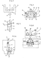
- La figure 1 représente, en élévation, une demi-coupe du dispositif de l'invention par un plan SS' de la figure 4 ;
- La figure 2 montre, en élévation, une pièce d'accouplement détachée de l'appareil ;
- La figure 3 montre une vue de côté en coupe partielle par le plan RR' de la figure 1 sans l'électro-aimant ;
- La figure 4 montre une vue de côté en coupe par le plan RR' de la figure 1 ;
- La figure 5 montre un détail de la figure 3 ;
- La figure 6 représente une vue analogue à celle de la figure 3, dans laquelle la pièce d'accouplement est légèrement modifiée ;
- La figure 7 illustre une vue de droite de l'électro-aimant représenté à la figure 4 ;
- La figure 8 représente, schématiquement, comment se fait l'association d'un appareil de l'invention avec un contacteur ; et
- Les figures 9 et 10 représentent deux variantes de réalisation du dispositif selon l'invention.
- Figure 1 shows, in elevation, a half-section of the device of the invention by a plane SS 'of Figure 4;
- Figure 2 shows, in elevation, a coupling part detached from the device;
- Figure 3 shows a side view in partial section through the plane RR 'of Figure 1 without the electromagnet;
- Figure 4 shows a side view in section through the plane RR 'of Figure 1;
- Figure 5 shows a detail of Figure 3;
- FIG. 6 represents a view similar to that of FIG. 3, in which the coupling part is slightly modified;
- Figure 7 illustrates a right view of the electromagnet shown in Figure 4;
- FIG. 8 represents, schematically, how an apparatus of the invention is made with a contactor; and
- Figures 9 and 10 show two alternative embodiments of the device according to the invention.
Dans un exemple de réalisation préféré de l'invention, visible à la figure 1, le dispositif de verrouillage 1 comporte un boîtier 2 formé par assemblage de deux demi-boîtiers 3 et 4 le long d'un plan de joint passant par XX'. Chaque demi-boîtier comporte, sur sa surface interne, un moyen de guidage tel qu'une rainure 5, respectivement 6, parallèle au plan de la figure, ces deux rainures étant parallèles et, extérieurement, un crochet 7, respectivement 8, qui forme, lorsque le boîtier est assemblé, une griffe de fixation pour rendre le boîtier solidaire d'un appareil interrupteur, tel qu'un contacteur 9. Chaque demi-boîtier comporte de plus une portion d'alésage 10, respectivement 11, ces deux portions venant en alignement lorsque les demi-boîtiers sont assemblés.In a preferred embodiment of the invention, visible in Figure 1, the
Une pièce d'accouplement 12 (voir aussi la figure 2) qui prend la forme d'un U ayant deux branches parallèles opposées 13, 14 et une traverse commune 15, est disposée dans le boîtier de façon à coulisser dans le plan de la figure 1 grâce au guidage qui lui est fourni lorsque les branches sont placées dans les rainures 5, respectivement 6.A coupling piece 12 (see also Figure 2) which takes the form of a U having two opposite
La traverse 15 présente un organe d'association 16, ayant par exemple la forme d'un T, qui traverse une ouverture inférieure 17 du boîtier pour devenir solidaire d'un organe mobile 18 du contacteur 9, provoquant le mouvement des contacts de ce dernier, ou portant ces contacts, et se trouvant solidaire de l'armature de ce contacteur (voir aussi la figure 8).The
Sur un côté de cette traverse, opposé à l'organe d'association, sont disposées deux surfaces d'appui 19 et 20 (ainsi qu'on le voit mieux à la figure 2). Ces deux surfaces, qui sont légèrement inclinées d'un angle S par rapport à un plan perpendiculaire à celui de la figure 2 (voir aussi la figure 5), se trouvent placées à deux niveaux nl, respectivement n2 différents, ces niveaux étant définis par rapport à la direction F ou G du déplacement rectiligne de la pièce d'accouplement.On one side of this cross member, opposite the association member, are arranged two bearing
En se reportant à la figure 1, on observe que les extrémités d'une tige cylindrique 21 ont été placées dans les alésages 10 et 11 pour constituer un arbre de pivotement commun à deux leviers 23, respectivement 24, dont les pivots sont 23a et 24a.Referring to FIG. 1, it can be seen that the ends of a
Ces leviers portent chacun, à leur extrémité libre respective 25, 26, une roulette 27. respectivement 28. Ces leviers sont, par ailleurs, soumis à des forces élastiques fournies par des ressorts tels que 23', respectivement 24', qui tendent à leur communiquer des mouvements de rotation de même sens a vers la pièce d'accouplement pour amener, comme expliqué ci-dessus, chaque roulette en contact avec une surface d'appui particulière (voir figures 3 et 1).These levers each carry, at their respective
Lorsque l'organe mobile 18 du contacteur 9 est déplacé vers le bas de la figure par son électro-aimant, dans le sens F, la pièce d'accouplement qui lui est associée effectue un mouvement identique. Lorsque le contacteur est au repos, la pièce d'accouplement 12 est en position inactive I et les deux leviers se trouvent chacun dans une position dégagée "D" contenue dans le plan DD' (voir aussi figure 3). Si la course effectuée atteint une première valeur C1, pour laquelle la pièce 12 atteint une première position active A1, l'une des roulettes, c'est-à-dire la roulette 28, qui est en regard de la surface d'appui 20, vient s'appuyer sur celle-ci pour la maintenir ultérieurement dans la position A1 qu'elle vient d'atteindre, le levier 24 étant alors en position engagée. Cette surface 20 est celle qui se trouve la plus éloignée de l'arbre de pivotement 21.When the
Si, pour les raisons exposées ci-dessus, la course effectuée atteint une seconde valeur C2' supérieure à la première, le second levier 23 prend également une position engagée dans le plan PP' et la seconde roulette 27 vient à son tour s'appuyer sur la surface d'appui 19, en regard, pour la maintenir dans la seconde position active A2 qu'elle vient d'at- teindre à son tour.If, for the reasons explained above, the stroke performed reaches a second value C 2 ' greater than the first, the
L'étagement des surfaces d'appui sera choisi en fonction de la course supplémentaire séparant C2 de C1 et de façon telle que, pour toute course supérieure ou égale à C1, la première roulette 28 s'engage au-dessus de la première surface 20 et que, pour toute course supérieure ou égale à C2, la seconde roulette 27 s'engage au-dessus de la seconde surface 19, la première roulette n'étant pas, dans ce dernier cas, utilisée pour verrouiller la première surface.The staging of the bearing surfaces will be chosen as a function of the additional stroke separating C 2 from C 1 and in such a way that, for any stroke greater than or equal to C 1 , the
C'est ainsi que, par exemple, pour toute course comprise entre 4,8 et 5,5 mm, seule la première roulette sera engagée, tandis que pour toute course supérieure à 5,5 mm (et par exemple comprise entre 5,5 mm et 6 mm), la première roulette sera d'abord engagée mais n'effectuera pas de verrouillage, celui-ci étant opéré ensuite par la seconde roulette dont le verrouillage se substituera à l'action de la première au-delà d'une course de 5,5 mm. Par ailleurs, l'angle β et la position de l'axe de pivotement des leviers 21 seront choisis pour que chaque levier et donc chaque roulette, puisse passer d'un côté à l'autre du plan PP' passant sensiblement par cet axe perpendiculairement à la surface de butée correspondante.Thus, for example, for any stroke between 4.8 and 5.5 mm, only the first caster will be engaged, while for any stroke greater than 5.5 mm (and for example between 5.5 mm and 6 mm), the first caster will first be engaged but will not lock, it will then be operated by the second caster, whose locking will replace the action of the first beyond a 5.5 mm stroke. Furthermore, the angle β and the position of the pivot axis of the
L'orientation que doit prendre un levier 23, 24, dans un plan PP' pour bloquer efficacement la pièce d'accouplement 12 peut être obtenue, soit par coopération d'une roulette telle que 28 (voir figure 4) avec une surface d'appui, telle que 29, portée par cete pièce 12 soit encore par coopération d'une surface 30, portée par le levier 24 au voisinage du pivot 21, avec une surface d'appui 31 du boîtier.The orientation that a
Un électro-aimant 32 destiné à effectuer le déverrouillage à distance des leviers comprend une carcasse 33, sur laquelle est disposée une bobine 34 reliée à des bornes telles que 35 et à l'intérieur de laquelle se trouve un alésage 36 servant éventuellement à guider un noyau plongeur 37 mobile le long d'un axe YY' perpendiculaire au plan de déplacement de la pièce d'accouplement. Une culasse en U, non représentée, est prévue pour refermer le flux de l'électro-aimant.An
Cette carcasse et cette bobine passent au niveau de la pièce d'accouplement entre les deux leviers, ce qui procure un gain de place ; la carcasse présente, en outre, une extrémité 38 qui s'appuye sur une paroi 39 du boîtier pour que sa position, par rapport aux leviers, soit bien définie dans la direction YY'.This carcass and this coil pass at the level of the coupling piece between the two levers, which saves space; the carcass has, in addition, an
La carcasse possède des joues, telles que 40, qui coopèrent par ailleurs avec les demi-boîtiers pour que sa position soit bien définie dans des directions perpendiculaires à YY'.The carcass has cheeks, such as 40, which also cooperate with the half-housings so that its position is well defined in directions perpendicular to YY ′.
Le noyau plongeur 37 porte, extérieurement à la bobine, un poussoir 41 présentant deux doigts 42, 43, parallèles à YY' qui sont placés en regard des deux leviers respectifs 23, 24 et un prolongement 44 qui traverse une rainure 45 du boîtier 2 et/ou de la carcasse ; ce prolongement possède un bouton d'actionnement manuel 46 qui permet d'effectuer une manoeuvre du plongeur indépendamment de la bobine.The
Un faible ressort de rappel 47 donne, à ce noyau-plongeur et à ce poussoir, une position de repos bien définie par appui de ce dernier sur une paroi 48 du boîtier, opposée à la paroi 39 ; éventuellement on peut se dispenser d'utiliser un tel ressort si la position du boîtier permet à la pesanteur d'exercer un rôle analogue.A
Les surfaces de butée 19, 20 de la pièce d'accouplement ont été orientées à la figure 5, selon un certain angle $ pour faciliter l'engagement des roulettes et pour faire que l'énergie nécessaire au déverrouillage soit très faible ; une telle mesure n'est pas indispensable pour que l'appareil puisse fonctionner car des surfaces 19', 20' (voir figure 6), pourraient également être placées perpendiculairement à leur direction de déplacement F, G à condition que la droite A passant sensiblement par le pivot 21 et par le point de contact 49 de la roulette 27, 28, fasse, avec cette surface 19' 20', un angle φ légèrement supérieur à 90° ; dans ce dernier cas, l'électro-aimant de déverrouillage 32 doit fournir une énergie supérieure à celle qui est nécessaire dans le cas précédent.The abutment surfaces 19, 20 of the coupling part have been oriented in FIG. 5, at a certain angle $ to facilitate the engagement of the rollers and to make the energy required for unlocking very low; such a measurement is not essential for the apparatus to function since
La figure 7 indique comment des rainures 50, 51, placées dans des joues latérales 52, 53 de la carcasse de bobine 33, permettent de guider des nervures 54, 55 du poussoir 41 lorsque le noyau plongeur 37 n'est pas guidé dans l'alésage 36. Les deux leviers 23, 24 seront, de préférence, identiques.FIG. 7 shows how
Afin de fournir à la bobine 34 de l'électro-aimant de déverrouillage 32 une impulsion de courant de courte durée, le circuit interne 56 comprend, en série (voir figure 8), un interrupteur 57 dont le contact mobile 58 est placé sur la pièce d'accouplement 12 (en particulier dans une fenêtre 60 de la branche 14) de façon que l'interrupteur soit fermé lorsque le contacteur 9 déplace, en sens F, cette pièce 12 et ouvert dans le cas contraire ; une seconde borne.55'termine le circuit d'alimentation interne 56.In order to supply the
Le fonctionnement de l'appareil 1 commence au moment où le contacteur 9 est excité et où la pièce d'accouplement est entraînée par la pièce 18 et contre l'action d'un ressort de rappel 59 dans le sens F en effectuant une course Ci ou C2 The operation of the
Dès que les surfaces d'appui 20 ou 19 se présentent en regard des roulettes 28 ou respectivement 27, après des courses correspondantes, le levier de verrouillage 24 ou, respectivement, 23 maintient la pièce d'accouplement dans une position active A telle que la pression sur les contacts du contacteur soit assurée ; si l'électro-aimant du contacteur est alors désexcité, son armature conserve pratiquement la même position.As soon as the bearing surfaces 20 or 19 appear opposite the
Pour effectuer l'ouverture des contacts du contacteur, une impulsion de courant est envoyée sur les bornes 35, 58 de l'appareil 1 et excite l'électro-aimant de déverrouillage 32 en raison de l'état de fermeture de l'interrupteur 57.To open the contactor contacts, a current pulse is sent to the
Le mouvement du plongeur provoque la percussion des leviers 23, 24 par le poussoir 41, dans le sens horaire de la figure 4 et, les surfaces d'appui 19, 20 échappant aux roulettes 27, 28, le ressort de rappel 59 de l'armature ou de la pièce 18 du contacteur 9 déplace la pièce d'accouplement 12 en sens G pour lui donner une position inactive I dans laquelle l'interrupteur 57 est ouvert.The movement of the plunger causes the
Le mode de réalisation préféré de l'invention qui a été illustré aux figures 1 à 7 peut être appliqué à une disposition mécanique, visible à la figure 9, qui ne présente pas les mêmes avantages.The preferred embodiment of the invention which has been illustrated in FIGS. 1 to 7 can be applied to a mechanical arrangement, visible in FIG. 9, which does not have the same advantages.
Dans ce second mode de réalisation 1", des leviers 23", 24", sont pivotés en 21" sur une pièce d'accouplement 12", tandis que les surfaces d'appui 19", 20" sont portées par la région supérieure d'un boîtier 2".In this
Bien que le fonctionnement soit ici analogue à celui du premier mode de réalisation, le fait de disposer les surfaces d'appui et les extrémités libres des leviers dans la région supérieure du boîtier 2", d'une part, réduit localement le volume qui doit être laissé aux bornes de raccordement et d'autre part, rend plus difficile le montage des ressorts de rappel de ces leviers.Although the operation here is analogous to that of the first embodiment, the fact of placing the bearing surfaces and the free ends of the levers in the upper region of the
Dans un troisième mode de réalisation de l'invention, visible à la figure 10, les deux leviers 23" ', 24 "', qui sont pivotés sur un même axe 21 "' dans un boîtier 2"', possèdent des longueurs ml et m2 différentes, tandis que les surfaces d'appui 19"', 20 "', qui sont placées sur une pièce d'accouplement 12"', se trouvent dans un même plan VV' ; ici encore, le fonctionnement est le même que dans les deux cas précédents, à savoir que les deux leviers s'engagent, l'un après l'autre, contre les surfaces d'appui pour effectuer le verrouillage lorsque la pièce d'accouplement effectue des courses de différentes amplitudes.In a third embodiment of the invention, visible in FIG. 10, the two
Il est clair que des résultats identiques pourraient être obtenus par combinaison des différentes mesures décrites précédemment ; c'est ainsi que l'on pourrait utiliser, soit à la fois des leviers de longueurs diférentes et des surfaces d'appui distinctes, soit encore des surfaces d'appui placées dans un même plan et des leviers de mêmes longueurs dont les axes de pivotement seraient décalés de façon à présenter leur roulette respective à deux niveaux distincts. Les solutions dans lesquelles les leviers ont les mêmes longueurs sont toutefois préférables en raison du fait qu'un seul type de levier peut être utilisé pour la réalisation du dispositif.It is clear that identical results could be obtained by combining the different measures described above; It is thus that one could use, either at the same time levers of different lengths and distinct bearing surfaces, or else bearing surfaces placed in the same plane and levers of the same lengths whose axes of pivoting would be shifted so as to present their respective caster at two distinct levels. Solutions in which the levers have the same lengths are however preferable due to the fact that only one type of lever can be used for the production of the device.
Enfin, dans un quatrième mode de réalisation, qui n'est pas représenté mais dont la constitution devient évidente pour l'homme de l'art, on peut également utiliser un premier levier porté par la pièce d'accouplement et apte à coopérer avec une surface d'appui placée dans le boîtier, et un second levier pivoté dans le boîtier et apte à coopérer avec une surface d'appui placée sur la pièce d'accouplement.Finally, in a fourth embodiment, which is not shown but whose constitution becomes obvious to those skilled in the art, it is also possible to use a first lever carried by the coupling part and able to cooperate with a bearing surface placed in the housing, and a second lever pivoted in the housing and able to cooperate with a bearing surface placed on the coupling part.
Claims (9)
caractérisé en ce qu'un second couple de leviers de verrouillage (23) et de surface d'appui (20) est placé dans le même boîtier (2), de façon à effectuer un second verrouillage de la pièce d'accouplement (12) lorsque celle-ci atteint une seconde position active (A2) voisine de la première (A,), le même électro-aimant de déverrouillage (32) étant utilisé pour replacer ces leviers (23, 24) en position dégagée (D).1. Removable device for locking in the working position of a movable contactor member which is put in the rest position by a return spring and which closes the power contacts of the contactor, in the working position, this device comprising , in a housing:
characterized in that a second pair of locking levers (23) and bearing surface (20) is placed in the same housing (2), so as to effect a second locking of the coupling part (12) when the latter reaches a second active position (A 2 ) close to the first (A,), the same unlocking electromagnet (32) being used to replace these levers (23, 24) in the released position (D).
caractérisé en ce qu'un second levier de verrouillage (23) est placé parallèlement au premier levier de verrouillage (24) et présente, à son extrémité libre, une seconde roulette (28) qui est apte à coopérer avec une seconde surface d'appui (20), placée sensiblement parallèlement à la première surface d'appui (19), lorsque la pièce d'accouplement (12) prend une seconde position active (A2) qui est plus éloignée de la position inactive (I) que ne l'est la première position active (Al).2. Locking device according to claim 1,
characterized in that a second locking lever (23) is placed parallel to the first locking lever (24) and has, at its free end, a second roller (28) which is able to cooperate with a second bearing surface (20), placed substantially parallel to the first bearing surface (19), when the part coupling (12) takes a second active position (A 2 ) which is further from the inactive position (I) than is the first active position (A l ).
caractérisé en ce que les deux leviers (23, 24) sont pivotés autour de pivots solidaires du boîtier, tandis que les surfaces d'appui (19, 20) sont disposées sur la pièce d'accouplement (12).3. Locking device according to claim 2,
characterized in that the two levers (23, 24) are pivoted around pivots integral with the housing, while the bearing surfaces (19, 20) are arranged on the coupling piece (12).
caractérisé en ce que les deux leviers sont pivotés sur la pièce d'accouplement tandis que les surfaces d'appui sont portées par le boîtier.4. Locking device according to claim 2,
characterized in that the two levers are pivoted on the coupling part while the bearing surfaces are carried by the housing.
caractérisé en ce que les deux leviers 23, 24 ont une même longueur et pivotent autour d'un même pivot (21), ces surfaces d'appui (19, 20) étant disposées à deux niveaux différents (n l, n 2).5. Locking device according to one of claims 3 or 4,
characterized in that the two levers 23, 24 have the same length and pivot around the same pivot (21), these bearing surfaces (19, 20) being arranged at two different levels ( n l , n 2 ).
caractérisé en ce que les deux leviers ont des longueurs (m1, m2) actives différentes, les deux surfaces d'appui étant placées dans un même plan VV'.6. Locking device according to one of claims 3 or 4,
characterized in that the two levers have different active lengths (m 1 , m 2 ), the two bearing surfaces being placed in the same plane VV '.
caractérisé en ce que les deux leviers (23, 24) sont placés de part et d'autre de la bobine (34) de l'électro-aimant de déverrouillage (32).7. Locking device according to one of claims 2 to 6,
characterized in that the two levers (23, 24) are placed on either side of the coil (34) of the electromagnet unlocking (32).
caractérisé en ce que la pièce d'accouplement (12) prend la forme d'un U dont les branches parallèles (13, 14) servent à la guider et dont une traverse (15) porte les surfaces d'appui (19, 20).8. Locking device according to one of claims 2, 3, 5, 6 or 7,
characterized in that the coupling part (12) takes the form of a U, the parallel branches (13, 14) of which serve to guide it and the crosspiece of which (15) carries the bearing surfaces (19, 20) .
caractérisé en ce qu'une branche (14) de la pièce d'accouplement porte un contact mobile (58) appartenant à un interrupteur (57) placé en série avec la bobine (34) de l'électro-aimant de déverrouillage (32).9. Locking device according to claim 8,
characterized in that a branch (14) of the coupling part carries a movable contact (58) belonging to a switch (57) placed in series with the coil (34) of the unlocking electromagnet (32) .
Applications Claiming Priority (2)
| Application Number | Priority Date | Filing Date | Title |
|---|---|---|---|
| FR8204681A FR2523763A1 (en) | 1982-03-19 | 1982-03-19 | REMOVABLE DEVICE FOR LOCKING A CONTACTOR IN ITS WORKING POSITION |
| FR8204681 | 1982-03-19 |
Publications (2)
| Publication Number | Publication Date |
|---|---|
| EP0089882A1 true EP0089882A1 (en) | 1983-09-28 |
| EP0089882B1 EP0089882B1 (en) | 1985-08-28 |
Family
ID=9272172
Family Applications (1)
| Application Number | Title | Priority Date | Filing Date |
|---|---|---|---|
| EP83400526A Expired EP0089882B1 (en) | 1982-03-19 | 1983-03-15 | Active-position removable latching device for a contactor |
Country Status (8)
| Country | Link |
|---|---|
| US (1) | US4490702A (en) |
| EP (1) | EP0089882B1 (en) |
| JP (1) | JPS58184222A (en) |
| BR (1) | BR8301314A (en) |
| CA (1) | CA1203825A (en) |
| DE (1) | DE3360644D1 (en) |
| ES (1) | ES8402115A1 (en) |
| FR (1) | FR2523763A1 (en) |
Cited By (2)
| Publication number | Priority date | Publication date | Assignee | Title |
|---|---|---|---|---|
| EP0578984A2 (en) * | 1992-07-16 | 1994-01-19 | Siemens Aktiengesellschaft | Interlocking block for electromagnetic switching devices |
| EP1638121A1 (en) * | 2003-05-29 | 2006-03-22 | Ping Liu | Electrical switch |
Families Citing this family (4)
| Publication number | Priority date | Publication date | Assignee | Title |
|---|---|---|---|---|
| DE3430090A1 (en) * | 1984-08-16 | 1986-03-06 | Euchner & Co, 7022 Leinfelden-Echterdingen | Safety switch |
| DE3524524C2 (en) * | 1985-07-05 | 1993-12-16 | Siemens Ag | Latching device for releasably latching switching devices in their switched-on position |
| ES2109860B1 (en) * | 1994-12-15 | 1998-08-01 | Power Controls Iberica Sl | MECHANICAL DETECTOR AND RETENTION DEVICE FOR A CONTACTOR TO MAINTAIN ITS CLOSING POSITION. |
| US10919717B2 (en) * | 2018-12-12 | 2021-02-16 | James N. Sinclair | Lifting device for blocks with non-parallel walls |
Citations (3)
| Publication number | Priority date | Publication date | Assignee | Title |
|---|---|---|---|---|
| US3201545A (en) * | 1962-02-28 | 1965-08-17 | Westinghouse Electric Corp | Electric control device |
| FR2353945A1 (en) * | 1976-06-04 | 1977-12-30 | Siemens Ag | ELECTROMAGNETIC RELAY |
| GB2075264A (en) * | 1980-05-01 | 1981-11-11 | Westinghouse Electric Corp | Mechanical latch for electric switches |
Family Cites Families (8)
| Publication number | Priority date | Publication date | Assignee | Title |
|---|---|---|---|---|
| FR733936A (en) * | 1932-03-21 | 1932-10-13 | Switch with two contactors, one of which has automatic circuit breaker | |
| FR755564A (en) * | 1932-05-13 | 1933-11-27 | Siemens Ag | Reed frequency relay having at least two differently tuned reeds which operate separately |
| GB675844A (en) * | 1951-01-12 | 1952-07-16 | British Tabulating Mach Co Ltd | Improvements in or relating to electromagnetic relays |
| BE534765A (en) * | 1954-01-28 | Merlin Gerin | ||
| GB988678A (en) * | 1961-05-02 | 1965-04-07 | Haegglund & Soener Ab | Multiple-pole electromagnetic contactor |
| GB1422934A (en) * | 1971-11-19 | 1976-01-28 | Square D Co | Latching attachment for a relay |
| US3882435A (en) * | 1974-06-28 | 1975-05-06 | Square D Co | Latch attachment for an electromagnetically operated switching device |
| US4185259A (en) * | 1978-01-19 | 1980-01-22 | Westinghouse Electric Corp. | Magnetic contactor with an adjustable latch release |
-
1982
- 1982-03-19 FR FR8204681A patent/FR2523763A1/en active Granted
-
1983
- 1983-03-15 EP EP83400526A patent/EP0089882B1/en not_active Expired
- 1983-03-15 DE DE8383400526T patent/DE3360644D1/en not_active Expired
- 1983-03-16 BR BR8301314A patent/BR8301314A/en not_active IP Right Cessation
- 1983-03-16 CA CA000423755A patent/CA1203825A/en not_active Expired
- 1983-03-18 ES ES520780A patent/ES8402115A1/en not_active Expired
- 1983-03-18 JP JP58045863A patent/JPS58184222A/en active Granted
- 1983-03-21 US US06/477,579 patent/US4490702A/en not_active Expired - Fee Related
Patent Citations (3)
| Publication number | Priority date | Publication date | Assignee | Title |
|---|---|---|---|---|
| US3201545A (en) * | 1962-02-28 | 1965-08-17 | Westinghouse Electric Corp | Electric control device |
| FR2353945A1 (en) * | 1976-06-04 | 1977-12-30 | Siemens Ag | ELECTROMAGNETIC RELAY |
| GB2075264A (en) * | 1980-05-01 | 1981-11-11 | Westinghouse Electric Corp | Mechanical latch for electric switches |
Cited By (4)
| Publication number | Priority date | Publication date | Assignee | Title |
|---|---|---|---|---|
| EP0578984A2 (en) * | 1992-07-16 | 1994-01-19 | Siemens Aktiengesellschaft | Interlocking block for electromagnetic switching devices |
| EP0578984A3 (en) * | 1992-07-16 | 1995-01-18 | Siemens Ag | Interlocking block for electromagnetic switching devices. |
| EP1638121A1 (en) * | 2003-05-29 | 2006-03-22 | Ping Liu | Electrical switch |
| EP1638121A4 (en) * | 2003-05-29 | 2009-02-25 | Ping Liu | Electrical switch |
Also Published As
| Publication number | Publication date |
|---|---|
| DE3360644D1 (en) | 1985-10-03 |
| CA1203825A (en) | 1986-04-29 |
| JPH0454331B2 (en) | 1992-08-31 |
| US4490702A (en) | 1984-12-25 |
| BR8301314A (en) | 1983-11-29 |
| FR2523763B1 (en) | 1984-06-08 |
| FR2523763A1 (en) | 1983-09-23 |
| EP0089882B1 (en) | 1985-08-28 |
| JPS58184222A (en) | 1983-10-27 |
| ES520780A0 (en) | 1984-01-01 |
| ES8402115A1 (en) | 1984-01-01 |
Similar Documents
| Publication | Publication Date | Title |
|---|---|---|
| EP0949511A1 (en) | Device for detecting the opening of a utility meter | |
| EP0174238A2 (en) | Monostably or bistably functioning polarised electromagnet | |
| EP0427641B1 (en) | Remote control unit for an electric circuit breaker | |
| EP0079818B1 (en) | Contactor device with means for automatically breaking power circuits and with a local operating device | |
| EP0089882B1 (en) | Active-position removable latching device for a contactor | |
| FR2953661A1 (en) | ELECTRIC POWER GENERATING DEVICE | |
| EP0080687B1 (en) | Rotary operated electric switch with automatic return in the case of voltage failure | |
| CA1182500A (en) | Contactor with automatic opening means and local control station | |
| CH635911A5 (en) | MANUALLY CONTROLLED FLUID VALVE. | |
| FR2599550A1 (en) | SWITCH FOR MOTOR VEHICLES | |
| FR2709370A1 (en) | Electromagnetic relay with bistable contact. | |
| EP0032870B1 (en) | Mechanism, mountable in a casing, for operating the displacement of a lever, and application of this mechanism as a circuit-breaker | |
| EP0866483B1 (en) | Bistable battery switch with mechanical interlock | |
| EP0168306B1 (en) | Bistable reversing device, especially for feeding an oxygen circuit in an airplane, and its application | |
| EP0271366B1 (en) | Remote control interrupter with an auxiliary change-over switch in its control circuit | |
| EP0676780A1 (en) | Electrical apparatus with push-button | |
| EP0827172B1 (en) | Actuator assembly for electrical contacts | |
| EP0114542A1 (en) | Contactor with electromagnetically controlled action and automatic opening in case of over-voltage | |
| FR2892849A1 (en) | Fixed and movable contacts locking mechanism for e.g. circuit breaker, has movable contact rigidly fixed to contact holder, and compression spring placed between flange and fixed contact | |
| FR2755999A1 (en) | AUTOMATIC STOP DEVICE FOR ROLLER SHUTTER OR THE LIKE | |
| EP0098194B1 (en) | Detector switch, especially for stoppage control of motor vehicle direction indicators | |
| EP0246131B1 (en) | Electrical bistable commutating device | |
| WO1984003173A1 (en) | Automatic protection switch with visible sectioning and hand reset | |
| FR2588692A1 (en) | Polarised electromagnetic actuator structure | |
| FR2552809A1 (en) | Lock with half-turn latch |
Legal Events
| Date | Code | Title | Description |
|---|---|---|---|
| PUAI | Public reference made under article 153(3) epc to a published international application that has entered the european phase |
Free format text: ORIGINAL CODE: 0009012 |
|
| 17P | Request for examination filed |
Effective date: 19830316 |
|
| AK | Designated contracting states |
Designated state(s): CH DE GB IT LI SE |
|
| ITF | It: translation for a ep patent filed | ||
| GRAA | (expected) grant |
Free format text: ORIGINAL CODE: 0009210 |
|
| AK | Designated contracting states |
Designated state(s): CH DE GB IT LI SE |
|
| REF | Corresponds to: |
Ref document number: 3360644 Country of ref document: DE Date of ref document: 19851003 |
|
| RIN2 | Information on inventor provided after grant (corrected) |
Free format text: DUMONT, ALAIN * FOURET, RENE |
|
| PLBE | No opposition filed within time limit |
Free format text: ORIGINAL CODE: 0009261 |
|
| STAA | Information on the status of an ep patent application or granted ep patent |
Free format text: STATUS: NO OPPOSITION FILED WITHIN TIME LIMIT |
|
| 26N | No opposition filed | ||
| ITTA | It: last paid annual fee | ||
| EAL | Se: european patent in force in sweden |
Ref document number: 83400526.6 |
|
| PGFP | Annual fee paid to national office [announced via postgrant information from national office to epo] |
Ref country code: GB Payment date: 19950307 Year of fee payment: 13 |
|
| PGFP | Annual fee paid to national office [announced via postgrant information from national office to epo] |
Ref country code: CH Payment date: 19950317 Year of fee payment: 13 |
|
| PGFP | Annual fee paid to national office [announced via postgrant information from national office to epo] |
Ref country code: SE Payment date: 19950324 Year of fee payment: 13 Ref country code: DE Payment date: 19950324 Year of fee payment: 13 |
|
| PG25 | Lapsed in a contracting state [announced via postgrant information from national office to epo] |
Ref country code: GB Effective date: 19960315 |
|
| PG25 | Lapsed in a contracting state [announced via postgrant information from national office to epo] |
Ref country code: SE Effective date: 19960316 |
|
| PG25 | Lapsed in a contracting state [announced via postgrant information from national office to epo] |
Ref country code: LI Effective date: 19960331 Ref country code: CH Effective date: 19960331 |
|
| GBPC | Gb: european patent ceased through non-payment of renewal fee |
Effective date: 19960315 |
|
| REG | Reference to a national code |
Ref country code: CH Ref legal event code: PL |
|
| PG25 | Lapsed in a contracting state [announced via postgrant information from national office to epo] |
Ref country code: DE Effective date: 19961203 |
|
| EUG | Se: european patent has lapsed |
Ref document number: 83400526.6 |