EP0089865A1 - Cassette with regulated-speed elastic belt - Google Patents
Cassette with regulated-speed elastic belt Download PDFInfo
- Publication number
- EP0089865A1 EP0089865A1 EP83400435A EP83400435A EP0089865A1 EP 0089865 A1 EP0089865 A1 EP 0089865A1 EP 83400435 A EP83400435 A EP 83400435A EP 83400435 A EP83400435 A EP 83400435A EP 0089865 A1 EP0089865 A1 EP 0089865A1
- Authority
- EP
- European Patent Office
- Prior art keywords
- roller
- belt
- loop
- sliding roller
- return
- Prior art date
- Legal status (The legal status is an assumption and is not a legal conclusion. Google has not performed a legal analysis and makes no representation as to the accuracy of the status listed.)
- Granted
Links
- 230000002093 peripheral effect Effects 0.000 claims abstract description 10
- 230000005540 biological transmission Effects 0.000 claims description 9
- 210000000056 organ Anatomy 0.000 description 3
- 230000015572 biosynthetic process Effects 0.000 description 1
- 238000005259 measurement Methods 0.000 description 1
- 230000001105 regulatory effect Effects 0.000 description 1
- 230000000717 retained effect Effects 0.000 description 1
- 238000011144 upstream manufacturing Methods 0.000 description 1
Images


Classifications
-
- G—PHYSICS
- G11—INFORMATION STORAGE
- G11B—INFORMATION STORAGE BASED ON RELATIVE MOVEMENT BETWEEN RECORD CARRIER AND TRANSDUCER
- G11B23/00—Record carriers not specific to the method of recording or reproducing; Accessories, e.g. containers, specially adapted for co-operation with the recording or reproducing apparatus ; Intermediate mediums; Apparatus or processes specially adapted for their manufacture
- G11B23/02—Containers; Storing means both adapted to cooperate with the recording or reproducing means
- G11B23/04—Magazines; Cassettes for webs or filaments
- G11B23/08—Magazines; Cassettes for webs or filaments for housing webs or filaments having two distinct ends
- G11B23/087—Magazines; Cassettes for webs or filaments for housing webs or filaments having two distinct ends using two different reels or cores
- G11B23/08707—Details
- G11B23/08778—Driving features, e.g. belt
-
- G—PHYSICS
- G11—INFORMATION STORAGE
- G11B—INFORMATION STORAGE BASED ON RELATIVE MOVEMENT BETWEEN RECORD CARRIER AND TRANSDUCER
- G11B15/00—Driving, starting or stopping record carriers of filamentary or web form; Driving both such record carriers and heads; Guiding such record carriers or containers therefor; Control thereof; Control of operating function
- G11B15/18—Driving; Starting; Stopping; Arrangements for control or regulation thereof
- G11B15/26—Driving record carriers by members acting directly or indirectly thereon
Definitions
- the present invention relates to a tape drive device, in particular for a magnetic recorder, comprising: a frame, two drums rotatably mounted in the same plane on said frame around two respective parallel axes; a strip surrounding at least one of the drums, the strip and the two drums on which it can be wound forming two coils connected by an accessible strip portion; a sliding roller rotating in the same plane as the coils and tangent to the periphery of each of these; and an endless belt, tensioned, capable of undergoing an elastic elongation, passing between the sliding roller and the reels, so as to define with respect to the places of the sliding roller / belt / reel contact, a first loop surrounding the sliding roller and a second loop coming to bear on an arc of the periphery of each of the coils to ensure the tension of the accessible portion of strip, this second loop passing around at least one idler roller mounted rotating around an axis fixed relative to the built.
- the object of the invention is to propose a device of the aforementioned type avoiding this kind of drawback.
- At least one idler roller of the second loop of the elastic belt is directly driven by a drive means so that the peripheral speed of the driven idler roller and the speed device of the sliding roller are maintained in a ratio belonging to the upper neighborhood of 1.
- the belt tension of the outer turn of the take-up reel is influenced, according to a function which has not yet been explained, by the friction of the regulating elastic belt, which rests on an arc on the periphery of said reel.
- the part of the belt directly affected by the phenomenon is the part of the second loop of the belt located between the roller / sliding / belt / coil contact and the (or one of the) belt return roller of interest in this second loop.
- control of the speed of the elastic belt in the region of the second loop considered is ensured when the peripheral speed of the driven idler roller and that of the sliding roller (serving as a reference) is maintained in a ratio constant belonging to the upper neighborhood of 1.
- a relative overspeed of the idler roller from 1 to 8% compared to the peripheral speed of the sliding roller generally represents a good choice.
- the overspeed is preferably 2%.
- the accessible strip portion 7 is unwound (in the example shown) from the reel 6 which rotates in the direction indicated by the arrow; it passes over the return capstan 8, in front of the magnetic head 9, over the return capstan 10, and is wound on the reel 5.
- An endless elastic belt 11 passes between the coils 5 and 6 and a sliding roller 12 which it maintains in tangent contact with the two coils (through the belt) on the side of the accessible strip.
- the two contact rollers 12 / belt 11 / coils 5,6 make it possible to distinguish topologically two loops of the belt; a first loop 11a which surrounds and applies the sliding roller 12 against the coils, and a second loop 11b corresponding to the part of the belt situated on the other side of the two contact lines. This second loop comes to bear on an arc of the periphery of each of the coils 5, 6 and is held taut while passing over two idler rollers 13, 14.
- the two return rollers 13 and 14 are located, relative to the sliding roller 12, on the same side of a plane which would contain the axes 3 and 4 of the drums 1 and 2.
- the solu The retained option has the advantage of offering a longer length of the coil arc wrapped by the belt, and of making it possible to use an elastic belt 11 of greater length for the same loader format, which is desirable for the exploitation of the elastic properties of the belt.
- the sliding roller 12 is t finely RAI in organ of the system, resulting in the tape by friction by means of the belt 11, at both 12 contacts roller / belt 11 / coil 5.6.
- the roller 12 is integral in rotation with a pinion 15 which is coaxial with it, which meshes with a pinion 16 of fixed axis 17. relative to the cassette frame.
- the pinion 16 which could be directly keyed onto the shaft of a motor, is, in the example shown, driven by a motor 18 placed sideways in the loader, by means of a practically inextensible transmission belt 19 passing over two disks 20 and 21 respectively coaxial with and integral in rotation with the motor shaft 18 and the pinion 16.
- the roller 14 is driven by passing the transmission belt 19 around a disc 22 coaxial with the roller 14 and integral in rotation with it.
- the radius of the disc 22 is chosen as a function of the dimensions of the other members to give the peripheral speed of the roller 14 the desired excess relative to that of the sliding roller 12, that is to say maintain the two speeds in a ratio between 1.01 and 1.08, and preferably equal to 1.02.
- the elasticity of the material of the belt 11 and that of the tensioned belt is chosen to be sufficient, as in the devices of the prior art, to guarantee reliable operation, over time (absence of creep), in wide temperature ranges, and to withstand jerky working conditions which induce very strong local constraints in very short times.
- the elastic elongation reserve of the belt before mounting is at least 50%, and that the elastic elongation reserve of the mounted belt is at least 10%.
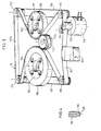
- FIG. 3 which represents another embodiment of the invention on a cassette, the magnetic strip of which is driven directly by pinching its accessible portion between two rollers, the bodies similar to those of FIGS. 1 and 2 have the same reference numeric, increased by 100.
- the accessible strip portion 107 is unwound from the supply reel 106; it passes over the return capstan 108, in front of the magnetic head 109; is pinched between the pressure roller 124 and the drive roller 125 mounted on the axis of the motor 118, passes over the return capstan 110, and is wound on the take-up reel 105.
- the elastic belt 111 forms a first loop llla around the sliding roller 112 and a second loop lllb around the two biconical deflection rollers 113 and 114, situated, with respect to the sliding roller 112, on the other side of a plane which would contain axes 103 and 104 of drums 1 and 2 of coils 105 and 106.
- the two belt return rollers 113, 114 are each driven by a belt return capstan 110, 108, by means of a transmission belt 126,127.
- This belt 126, 127 can be a toroidal belt passing through a groove 128 (cf. FIG. 4) provided on the rollers 113, 114 or capstans 108,. 110 at a level which does not hinder the running of the belt or the strip.
- the respective diameters of the grooves 128 of a capstan 108, 110, and of its associated driven roller 114, 113 are calculated as a function of the diameter of the capstan and roller at the level of the travel of the strip and of the elastic belt 111 to ensure that the idler rollers 114, 113 the desired overspeed relative to the sliding roller 112.
- the ratio of the peripheral speeds between the idler roller 113 and the sliding roller 112 is by neglecting the thicknesses of the belts and band, as well as possible possible slippages, in particular between the band 107 and the capstan 110 (or 108) which must transmit a torque to the idler roller 113 (or 114).
- the values indicated above give good satisfaction and ensure good tension of the magnetic strip on the take-up reel 105.
- the two belt return rollers shown by the two belt return capstans have been shown for added safety, it would be possible, as in the first embodiment, to drive only one of the capstans, or to pass through a single transmission belt on a capstan and two rollers, two capstans and a roller, the two capstans and the two rollers.
Abstract
Dans le cadre d'un dispositif d'entraînement de bande comprenant notamment un galet baladeur (12) tangent aux bobines (5, 6), et une courroie élastique sans fin (11) passant entre le galet baladeur (12) et les bobines (5, 6) en formant une première boucle (11a) entourant le galet baladeur (12) et une seconde boucle (11b) venant en appui sur un arc de la périphérie de chacune des bobines (5, 6) pour assurer la tension de la portion de bande accessible (7), cette seconde boucle (11b) passant autour d'au moins un galet de renvoi (13, 14), l'invention prévoit que au moins un galet de renvoi (14) est directement entraîné par un moyen d'entraînement (18, 19), de manière que la vitesse périphérique du galet de renvoi entraîné (14) et la vitesse périphérique du galet baladeur (12) soient maintenues dans un rapport appartenant au voisinage supérieur de 1, en vue d'assurer une meilleure tension de bande sur la bobine réceptrice.In the context of a belt drive device comprising in particular a sliding roller (12) tangent to the reels (5, 6), and an endless elastic belt (11) passing between the sliding roller (12) and the reels ( 5, 6) by forming a first loop (11a) surrounding the sliding roller (12) and a second loop (11b) bearing on an arc of the periphery of each of the coils (5, 6) to ensure the tension of the accessible strip portion (7), this second loop (11b) passing around at least one deflection roller (13, 14), the invention provides that at least one deflection roller (14) is directly driven by means drive (18, 19), so that the peripheral speed of the driven idler roller (14) and the peripheral speed of the sliding roller (12) are maintained in a ratio belonging to the upper vicinity of 1, in order to ensure better web tension on the take-up reel.
Description
La présente invention concerne un dispositif d'entraînement de bande, notamment pour enregistreur magnétique, comprenant : un bâti, deux tambours montés tournants dans un même plan sur ledit bâti autour de deux axes parallèles respectifs ; une bande entourant l'un au moins .des tambours, la bande et les deux tambours sur lesquels elle peut s'enrouler formant deux bobines reliées par une portion de bande accessible ; un galet baladeur tournant dans le même plan que les bobines et tangent à la périphérie de chacune de celles-ci ; et une courroie sans fin, tendue,susceptible de subir un allongement élastique, passant entre le galet baladeur et les bobines,de manière a définir par rapport aux endroits du contact galet baladeur/courroie/bobine, une première boucle entourant le galet baladeur et une seconde boucle venant en appui sur un arc de la périphérie de chacune des bobines pour assurer la tension de la portion de bande accessible, cette seconde boucle passant autour d'au moins un galet de renvoi monté tournant autour d'un axe fixe par rapport au bâti.The present invention relates to a tape drive device, in particular for a magnetic recorder, comprising: a frame, two drums rotatably mounted in the same plane on said frame around two respective parallel axes; a strip surrounding at least one of the drums, the strip and the two drums on which it can be wound forming two coils connected by an accessible strip portion; a sliding roller rotating in the same plane as the coils and tangent to the periphery of each of these; and an endless belt, tensioned, capable of undergoing an elastic elongation, passing between the sliding roller and the reels, so as to define with respect to the places of the sliding roller / belt / reel contact, a first loop surrounding the sliding roller and a second loop coming to bear on an arc of the periphery of each of the coils to ensure the tension of the accessible portion of strip, this second loop passing around at least one idler roller mounted rotating around an axis fixed relative to the built.
Des dispositifs de ce type sont connus par le brevet des Etats-Unis, n° 3.907.230 auquel on pourra se reporter pour apprécier le rôle de la courroie élastique.Devices of this type are known from the United States patent, No. 3,907,230 to which reference may be made in order to assess the role of the elastic belt.
Si ces dispositifs ont su donner entière satisfaction même dans des conditions sévères d'utilisation, il est cependant apparu que les bobines de bande avaient tendance à former des paquets de spires disjoints lorsqu'elles sont stockées à basse température.If these devices have been able to give complete satisfaction even under severe conditions of use, it has however appeared that the tape reels tend to form bundles of disjointed turns when they are stored at low temperature.
Le but de l'invention est de proposer un dispositif du type précité évitant ce genre d'inconvénient.The object of the invention is to propose a device of the aforementioned type avoiding this kind of drawback.
A cette fin, dans le dispositif conforme à l'invention, au moins un galet de renvoi de la seconde boucle de la courroie élastique est directement entraîné par un moyen d'entraînement de manière que la vitesse périphérique du galet de renvoi entraîné et la vitesse périphérique du galet baladeur soient maintenues dans un rapport appartenant au voisinage supérieur de 1.To this end, in the device according to the invention, at least one idler roller of the second loop of the elastic belt is directly driven by a drive means so that the peripheral speed of the driven idler roller and the speed device of the sliding roller are maintained in a ratio belonging to the upper neighborhood of 1.
En effet, il a été découvert, dans le cadre de l'invention,par des mesures effectuées sur des dispositifs de l'art antérieur de la tension de la spire extérieure de la bande sur la bobine réceptrice, que cette tension, qui varie d'ailleurs en fonction du remplissage de la bobine, pouvait, dans des conditions défavorables, s'annuler, voir même laisser place à un relâchement ou mou de la bande, avec comme conséquence, la formation de vides séparant des paquets de spires de la bobine enroulée.In fact, it has been discovered, within the framework of the invention, by measurements carried out on devices of the prior art of the tension of the external turn of the strip on the take-up reel, that this tension, which varies d 'elsewhere depending on the filling of the coil, could, under unfavorable conditions, cancel, or even give way to a slackening or slack of the strip, with as a consequence, the formation of voids separating packages of turns from the coil rolled up.
Or, la tension de bande de la spire extérieure de la bobine réceptrice est influencée, suivant une fonction d'ailleurs non encore explicitée,par le frottement de la courroie élastique régulatrice, qui s'appuie sur un arc de la périphérie de ladite bobine. La partie de la courroie directement concernée par le phénomène est la partie de la seconde boucle de la courroie située entre le contact galet/baladeur/courroie/bobine et le (ou l'un des) galet de renvoi de courroie intéressant cette seconde boucle.However, the belt tension of the outer turn of the take-up reel is influenced, according to a function which has not yet been explained, by the friction of the regulating elastic belt, which rests on an arc on the periphery of said reel. The part of the belt directly affected by the phenomenon is the part of the second loop of the belt located between the roller / sliding / belt / coil contact and the (or one of the) belt return roller of interest in this second loop.
On s'est aperçu, dans le cadre de l'invention, que l'annulation de tension de la spire extérieure de la bande, pouvait être considérée comme due à une perte de vitesse locale de la courroie élastique en aval du contact galet baladeur/courroie/bobine. Autrement dit, dans les dispositifs de l'art antérieur où le galet de renvoi de courroie est un galet libre, rien ne permet de combattre cette perte locale de vitesse, même si, évidemment, elle se trouve rattrapée globalement à un niveau mal déterminé, en considérant la totalité de la courroie. L'invention, au contraire, s'oppose au freinage local de la courroie en imposant, grâce à un entraînement direct adéquat du galet de renvoi, une survitesse pour maintenir en toutes circonstances la tension minimum de bande sur la bobine d'enroulement à une valeur de seuil positive (par exemple de 10 à 20 g de tension).It has been found, within the framework of the invention, that the tension cancellation of the outer turn of the band could be considered to be due to a local speed loss of the elastic belt downstream of the sliding roller contact / belt / reel. In other words, in the devices of the prior art where the belt return roller is a free roller, nothing makes it possible to combat this local loss of speed, even if, obviously, it is caught up overall at a badly determined level, considering the entire belt. The invention, on the contrary, opposes the local braking of the belt by imposing, thanks to an adequate direct drive of the deflection roller, an overspeed to maintain in all circumstances the minimum belt tension on the take-up reel at a positive threshold value (for example from 10 to 20 g of tension ).
Ainsi, selon l'invention, la maîtrise de la vitesse de la courroie élastique dans la région de la seconde boucle considérée est assurée quand on maintient la vitesse périphérique du galet de renvoi entraîné et celle du galet baladeur (servant de référence) dans un rapport constant appartenant au voisinage supérieur de 1.Thus, according to the invention, control of the speed of the elastic belt in the region of the second loop considered is ensured when the peripheral speed of the driven idler roller and that of the sliding roller (serving as a reference) is maintained in a ratio constant belonging to the upper neighborhood of 1.
Quoique les valeurs précises adoptées en pratique dépendent de plusieurs facteurs et notamment de l'élasticité de la courroie, une survitesse relative du galet de renvoi de 1 à 8 % par rapport à la vitesse périphérique du galet baladeur représente en général un bon choix. La survitesse est de préférence de 2 %.Although the precise values adopted in practice depend on several factors and in particular on the elasticity of the belt, a relative overspeed of the idler roller from 1 to 8% compared to the peripheral speed of the sliding roller generally represents a good choice. The overspeed is preferably 2%.
Il est avantageux de maintenir constant le rapport des vitesses périphériques du galet de renvoi et du galet baladeur en les reliant cinématiquement à un organe moteur commun, via une transmission cinétique constante directe ou indirecte ; on choisit avantageusement pour réduire le poids et l'inertie de l'ensemble, une transmission par courroie légère et inextensible.It is advantageous to keep the ratio of the peripheral speeds of the idler roller and of the sliding roller constant by connecting them kinematically to a common motor member, via a direct or indirect constant kinetic transmission; advantageously chosen to reduce the weight and inertia of the assembly, a light and inextensible belt transmission.
L'invention sera mieux comprise grâce à la description qui va suivre de deux modes de réalisation préférés en référence aux dessins annexés sur lesquels :
- - la figure 1 représente en perspective les organes essentiels d'un dispositif de l'invention, dans le cadre d'un chargeur a entraînement de bande par le galet baladeur ;
- - la figure 2 représente en vue de dessous le chargeur complet de la fig. 1, couvercle enlevé ;
- - la figure 3 représente, en perspective analogue à la fig. l, un second dispositif de l'invention dans le cadre d'une cassette à entraînement de bande par pincement direct ;
- - la figure 4 est une coupe schématique d'un cabestan de renvoi de bande de la cassette de la figure 3.
- - Figure 1 shows in perspective the essential organs of a device of the invention, in the context of a tape drive charger by the sliding roller;
- - Figure 2 shows a bottom view of the complete charger of fig. 1, cover removed;
- - Figure 3 shows, in perspective similar to FIG. l, a second device of the invention in the context of a tape drive cassette by direct pinching;
- FIG. 4 is a diagrammatic section of a capstan for returning the tape from the cassette in FIG. 3.
On voit sur les figures 1 et 2 deux tambours 1 et 2 montés tournants dans un même plan autour de deux axes parallèles respectifs 3, 4 liés au bâti 23 d'une cassette ou chargeur. Une bande magnétique entoure les tambours 1 et 2 de façon à former deux bobines .5 et 6 reliées par une portion de bande accessible 7.We see in Figures 1 and 2 two
La portion de bande accessible 7 est déroulée (dans l'exemple représenté) de la bobine 6 qui tourne dans le sens indiqué par la flèche ; elle passe sur le cabestan de renvoi 8, devant la tête magnétique 9, sur le cabestan de renvoi 10, et s'enroule sur la bobine 5.The
Une courroie élastique sans fin 11 passe entre les bobines 5 et 6 et un galet baladeur 12 qu'elle maintient en contact tangent avec les deux bobines (au travers de la courroie) du côté de la bande accessible. Les deux lignes de contact galet baladeur 12/courroie 11/ bobines 5,6 permettent de distinguer topologiquement deux boucles de la courroie ; une première boucle lla qui entoure et applique le galet baladeur 12 contre les bobines, et une seconde boucle llb correspondant à la partie de courroie située de l'autre côté des deux lignes de contact. Cette seconde boucle vienten appui sur un arc de la périphérie de chacune des bobines 5, 6 et est maintenue tendue en passant sur deux galets de renvoi 13, 14.An endless
Dans l'exemple représenté, les deux galets de renvoi 13 et 14 sont situés, par rapport au galet baladeur 12, d'un même côté d'un plan qui contiendrait les axes 3 et 4 des tambours 1 et 2. Par rapport à la solution alternative consistant à implanter les galets de renvoi et donc toute la seconde boucle de l'autre côté dudit plan par rapport au galet baladeur, la solution retenue présente l'avantage d'offrir une plus grande longueur d'arc de bobine enveloppé par la courroie, et de permettre d'utiliser une courroie élastique 11 de plus grande longueur pour un même format de chargeur, ce qui est souhaitable pour l'exploitation des propriétés élastiques de la courroie.In the example shown, the two
Le galet baladeur 12 est l'organe d'entraî- nement du système, entraînant la bande par friction par l'intermédiaire de la courroie 11, au niveau des deux contacts galet 12/courroie 11/bobine 5,6.The
Selon un montage connu par la demande de brevet français n° 80 26362 au nom de la Demanderesse, le galet 12 est solidaire en rotation d'un pignon 15 qui lui est coaxial, lequel engrène avec un pignon 16 d'axe 17 fixe .par rapport au bâti de la cassette.. Le pignon 16 qui pourrait être directement claveté sur l'arbre d'un moteur, est, dans l'exemple représenté, entraîné par un moteur 18 placé de côté dans le chargeur, par l'intermédiaire d'une courroie de transmission 19 pratiquement inextensible passant sur deux disques 20 et 21 respectivement coaxiaux à et solidaires en rotation avec l'arbre du moteur 18 et le pignon 16.According to an arrangement known from French patent application No. 80 26362 in the name of the Applicant, the
Afin de communiquer à la spire extérieure de la bobine 5, partiellement enveloppée par la partie de seconde boucle 11b de courroie élastique 11 juste en aval du contact galet 12/courroie 11/bobine 5, une tension minimum suffisante, on combat les pertes de vitesse locales de ladite partie de seconde boucle llb (c'est-à-dire la partie amont de seconde boucle llb, en se référant au sens de défilement) en entraînant directement la courroie 11 au niveau d'au moins un des deux galets de renvoi 13, 14. L'expérience montre que l'action sur un seul des galets est suffisante, le choix du galet étant sans importance et indépendant du sens de déroulement de bande.In order to communicate to the outer turn of the
Pour ce faire, on entraîne le galet 14 en faisant passer la courroie de transmission 19 autour d'un disque 22 coaxial au galet 14 et solidaire en rotation avec lui.To do this, the
Le rayon du disque 22 est choisi en fonction des dimensions des autres organes pour donner à la vitesse périphérique du galet 14 l'excès désiré par rapport à celle du galet baladeur 12, c'est-à-dire maintenir les deux vitesses dans un rapport compris entre 1,01 et 1,08, et, de préférence, égal à 1,02.The radius of the
L'élasticité du matériau de la courroie 11 et celle de la courroie tendue est choisie suffisante, comme dans les dispositifs de l'art antérieur, pour garantir fonctionnement fiable, dans le temps (absence de fluage),dans de larges domaines dé températures, et pour supporter des conditions de travail par à-coups qui induisent des contraintes locales très fortes dans des temps très courts.The elasticity of the material of the
On peut retenir qu'il est souhaitable que la réserve d'allongement élastique de la courroie avant montage soit d'au moins 50 %, et que la réserve d'allongement élastique de la courroie montée soit d'au moins 10 %.It can be remembered that it is desirable that the elastic elongation reserve of the belt before mounting is at least 50%, and that the elastic elongation reserve of the mounted belt is at least 10%.
Ainsi, dans deux exemples d'application différents, on a pu monter deux courroies respectivement de 1,4 mm d'épaisseur au repos, tendue à 14 % (avec une réserve de 36 X), et de 1 mm d'épaisseur au repos, tendue à 31 % (avec une réserve d'allongement de 19 %). Les courroies n'ont pas la même épaisseur, compte tenu du fait que, pour obtenir une même tension de bande, l'épaisseur de la courroie doit diminuer quand l'allongement augmente.Thus, in two different application examples, it was possible to mount two belts respectively 1.4 mm thick at rest, stretched to 14% (with a reserve of 36 X), and 1 mm thick at rest , stretched to 31% (with an elongation reserve of 19%). The belts do not have the same thickness, taking into account that, to obtain the same belt tension, the thickness of the belt must decrease as the elongation increases.
Dans un autre exemple d'application particulièrement satisfaisant pour la sécurité dans le temps et les températures extrêmes, on a utilisé pour la courroie 11 un matériau ayant une capacité d'allongement de 700% à 800%, la courroie étant tendue à 30 X. La très grande réserve d'allongement disponible recommande cette application pour une utilisation de la cassette avec des va-et- vient fréquents de la bande.In another example of an application which is particularly satisfactory for safety over time and at extreme temperatures, a material having an elongation capacity of 700% to 800% was used for the
Sur la figure 3, qui représente un autre mode de réalisation de l'invention sur une cassette dont la bande magnétique est entraînée directement par pincement de sa portion accessible entre deux galets, les organes analogues à ceux des figures 1 et 2 portent la même référence numérique, augmentée de 100.In FIG. 3, which represents another embodiment of the invention on a cassette, the magnetic strip of which is driven directly by pinching its accessible portion between two rollers, the bodies similar to those of FIGS. 1 and 2 have the same reference numeric, increased by 100.
La portion de bande accessible 107 est déroulée de la bobine débitrice 106 ; elle passe sur le cabestan de renvoi 108, devant la tête magnétique 109 ; est pincée entre le galet presseur 124 et le galet d'entraînement 125 monté sur l'axe du moteur 118, passe sur le cabestan de renvoi 110, et s'enroule sur la bobine réceptrice 105.The
La courroie élastique 111 forme une première boucle llla autour du galet baladeur 112 et une seconde boucle lllb autour des deux galets de renvoi biconiques 113 et 114, situés, par rapport au galet baladeur 112, de l'autre côté d'un plan qui contiendrait les axes 103 et 104 des tambours 1 et 2 des bobines 105 et 106.The
Dans ce mode de réalisation, les deux galets de renvoi de courroie 113, 114 sont entraînés chacun par un cabestan de renvoi de bande 110, 108, au moyen d'une courroie de transmission 126,127. Cette courroie 126, 127 peut être une courroie torique passant dans une gorge 128 (cf. fig. 4) prévue sur les galets 113,114 ou cabestans 108,.110 à un niveau ne gênant pas le défilement de la courroie ou de la bande.In this embodiment, the two
Les diamètres respectifs des gorges 128 d'un cabestan.108, 110, et de son galet entraîné associé 114, 113 sont calculés en fonction du diamètre des cabestan et galet au niveau du défilement de la bande et de la courroie élastique 111 pour assurer aux galets de renvoi 114, 113 la survitesse désirée par rapport au galet baladeur 112.The respective diameters of the
A titre d'exemple, avec un cabestan de renvoi 110 de diamètre de 14 mm au niveau de la bande, et 12,5 mm au niveau de la gorge 128, un galet de renvoi 113 de diamètre 14,5 mm au niveau de la courroie 111 et 11,5 mm au niveau de la gorge 128, le rapport des vitesses périphériques entre le galet de renvoi 113 et le galet baladeur 112 est de![]()
![]()
Bien qu'on ait représenté les deux galets de renvoi de courroie entraînéspar les deux cabestans de renvoi de bande par surcroît de sécurité, on pourrait, comme dans le premier mode de réalisation, n'entraîner qu'un seul des cabestans, ou faire passer une courroie de transmission unique sur un cabestan et deux galets, deux cabestans et un galet, les deux cabestans et les deux galets.Although the two belt return rollers shown by the two belt return capstans have been shown for added safety, it would be possible, as in the first embodiment, to drive only one of the capstans, or to pass through a single transmission belt on a capstan and two rollers, two capstans and a roller, the two capstans and the two rollers.
Claims (8)
Applications Claiming Priority (2)
| Application Number | Priority Date | Filing Date | Title |
|---|---|---|---|
| FR8204546 | 1982-03-17 | ||
| FR8204546A FR2523754A1 (en) | 1982-03-17 | 1982-03-17 | ELASTIC BELT CASSETTE WITH CONTROLLED SPEED |
Publications (2)
| Publication Number | Publication Date |
|---|---|
| EP0089865A1 true EP0089865A1 (en) | 1983-09-28 |
| EP0089865B1 EP0089865B1 (en) | 1985-06-26 |
Family
ID=9272106
Family Applications (1)
| Application Number | Title | Priority Date | Filing Date |
|---|---|---|---|
| EP83400435A Expired EP0089865B1 (en) | 1982-03-17 | 1983-03-03 | Cassette with regulated-speed elastic belt |
Country Status (6)
| Country | Link |
|---|---|
| US (1) | US4488690A (en) |
| EP (1) | EP0089865B1 (en) |
| JP (1) | JPS58171762A (en) |
| CA (1) | CA1199722A (en) |
| DE (1) | DE3360317D1 (en) |
| FR (1) | FR2523754A1 (en) |
Cited By (2)
| Publication number | Priority date | Publication date | Assignee | Title |
|---|---|---|---|---|
| FR2561426A1 (en) * | 1984-03-19 | 1985-09-20 | Enertec | DEVICE FOR DRIVING MAGNETIC STRIP BY PINCHING AND APPLICATION |
| EP0565770A2 (en) * | 1992-04-15 | 1993-10-20 | Tandberg Data A/S | Capstan belt drive |
Families Citing this family (3)
| Publication number | Priority date | Publication date | Assignee | Title |
|---|---|---|---|---|
| US4607808A (en) * | 1985-01-16 | 1986-08-26 | Minnesota Mining And Manufacturing Company | Wear-resistant capstan for belt driven cartridge |
| JPH10502200A (en) * | 1994-06-15 | 1998-02-24 | イメイション・コーポレイション | Motor control of tape tension in belt cartridge |
| JP3422081B2 (en) * | 1994-07-29 | 2003-06-30 | ソニー株式会社 | Data cartridge |
Citations (8)
| Publication number | Priority date | Publication date | Assignee | Title |
|---|---|---|---|---|
| US2658398A (en) * | 1948-06-29 | 1953-11-10 | Rca Corp | Magnetic sound-recording and reproducing machine |
| FR1395958A (en) * | 1964-04-13 | 1965-04-16 | Advanced device for winding web at constant speed | |
| US4159811A (en) * | 1976-11-22 | 1979-07-03 | Grant Frederic F | Tape transport cartridge |
| US4162774A (en) * | 1977-10-17 | 1979-07-31 | Verbatim Corporation | Belt drive cartridge |
| FR2420817A1 (en) * | 1978-03-21 | 1979-10-19 | Urss Depart Relations Ext Mini | Cassette tape tension maintaining device for aircraft - uses flexible and non-extendable belt drives with two deflector shafts |
| US4172569A (en) * | 1977-01-12 | 1979-10-30 | Newell Research Corporation | Tape transport system with peripheral belt drive |
| US4199794A (en) * | 1977-01-12 | 1980-04-22 | Newell Research Corporation | Dual tape transport system with tensioning means |
| EP0055150A1 (en) * | 1980-12-12 | 1982-06-30 | Enertec | Tape drive device with mobile drive roller |
Family Cites Families (3)
| Publication number | Priority date | Publication date | Assignee | Title |
|---|---|---|---|---|
| CH575636A5 (en) * | 1972-08-21 | 1976-05-14 | Schlumberger Inst System | |
| US4209144A (en) * | 1977-11-10 | 1980-06-24 | Verbatim Corporation | Floating roller tape cartridge |
| US4205808A (en) * | 1979-01-22 | 1980-06-03 | Verbatim Corporation | Tape cartridge |
-
1982
- 1982-03-17 FR FR8204546A patent/FR2523754A1/en active Granted
-
1983
- 1983-03-03 EP EP83400435A patent/EP0089865B1/en not_active Expired
- 1983-03-03 DE DE8383400435T patent/DE3360317D1/en not_active Expired
- 1983-03-10 US US06/474,073 patent/US4488690A/en not_active Expired - Fee Related
- 1983-03-15 CA CA000423674A patent/CA1199722A/en not_active Expired
- 1983-03-17 JP JP58045240A patent/JPS58171762A/en active Granted
Patent Citations (8)
| Publication number | Priority date | Publication date | Assignee | Title |
|---|---|---|---|---|
| US2658398A (en) * | 1948-06-29 | 1953-11-10 | Rca Corp | Magnetic sound-recording and reproducing machine |
| FR1395958A (en) * | 1964-04-13 | 1965-04-16 | Advanced device for winding web at constant speed | |
| US4159811A (en) * | 1976-11-22 | 1979-07-03 | Grant Frederic F | Tape transport cartridge |
| US4172569A (en) * | 1977-01-12 | 1979-10-30 | Newell Research Corporation | Tape transport system with peripheral belt drive |
| US4199794A (en) * | 1977-01-12 | 1980-04-22 | Newell Research Corporation | Dual tape transport system with tensioning means |
| US4162774A (en) * | 1977-10-17 | 1979-07-31 | Verbatim Corporation | Belt drive cartridge |
| FR2420817A1 (en) * | 1978-03-21 | 1979-10-19 | Urss Depart Relations Ext Mini | Cassette tape tension maintaining device for aircraft - uses flexible and non-extendable belt drives with two deflector shafts |
| EP0055150A1 (en) * | 1980-12-12 | 1982-06-30 | Enertec | Tape drive device with mobile drive roller |
Cited By (5)
| Publication number | Priority date | Publication date | Assignee | Title |
|---|---|---|---|---|
| FR2561426A1 (en) * | 1984-03-19 | 1985-09-20 | Enertec | DEVICE FOR DRIVING MAGNETIC STRIP BY PINCHING AND APPLICATION |
| EP0156723A1 (en) * | 1984-03-19 | 1985-10-02 | Schlumberger Industries | Device for driving a magnetic tape by pinching, and its use |
| US4624399A (en) * | 1984-03-19 | 1986-11-25 | Enertec | Gripping drive for magnetic tape |
| EP0565770A2 (en) * | 1992-04-15 | 1993-10-20 | Tandberg Data A/S | Capstan belt drive |
| EP0565770A3 (en) * | 1992-04-15 | 1994-07-20 | Tandberg Data | Capstan belt drive |
Also Published As
| Publication number | Publication date |
|---|---|
| US4488690A (en) | 1984-12-18 |
| EP0089865B1 (en) | 1985-06-26 |
| FR2523754B1 (en) | 1984-06-15 |
| JPH0234101B2 (en) | 1990-08-01 |
| CA1199722A (en) | 1986-01-21 |
| FR2523754A1 (en) | 1983-09-23 |
| DE3360317D1 (en) | 1985-08-01 |
| JPS58171762A (en) | 1983-10-08 |
Similar Documents
| Publication | Publication Date | Title |
|---|---|---|
| CA1061900A (en) | Tape drive system | |
| EP0340101B1 (en) | Cassette for storing and dispensing filaments or slivers with a preregulated tension, for use in a machine for producing hollow bodies by filament winding | |
| FR2475775A1 (en) | MAGNETIC TAPE RECORDING AND / OR REPRODUCING DEVICE | |
| EP2454930B1 (en) | Transmission device for self-propelled vehicle and self-propelled vehicle provided with such a transmission | |
| EP0089865B1 (en) | Cassette with regulated-speed elastic belt | |
| EP0055150B1 (en) | Tape drive device with mobile drive roller | |
| FR2484120A1 (en) | APPARATUS FOR RECORDING AND REPRODUCING VIDEO SIGNALS | |
| FR2604856A1 (en) | Large baler with wrapping device | |
| FR2544825A1 (en) | Device for selectively controlling the rotational movement of a shaft | |
| FR2545254A1 (en) | MAGNETIC STRIP APPARATUS | |
| EP0409743B1 (en) | Yarn-tensioning device for textile machines | |
| EP0466608A1 (en) | Cassette for tape, comprising means for holding rotatable components mounted in the cassette in a predermined axial position | |
| EP0387135A1 (en) | Belt-tensioning device for a power transmission | |
| EP0374059A1 (en) | Yarn-tensioning device for textile machines | |
| FR2565568A1 (en) | PROCESS FOR UNWINDING A MACHINE ROLL IN A MOUSELINE PAPER CUTTER OR THE LIKE | |
| BE529811A (en) | ||
| FR2474231A1 (en) | Ribbon winding machine for electrical cables etc. - has constant couple drive and self tensioning lever roller system for guiding ribbon | |
| FR1274750A (en) | Reels cradles improvements | |
| FR2517860A1 (en) | MAGNETIC TAPE DRIVE MECHANISM | |
| FR1464352A (en) | Control device for advancing recording tapes | |
| BE516641A (en) | ||
| FR2510088A1 (en) | VOLTAGE CONTROL APPARATUS AND WIRE COMPENSATION | |
| FR2569036A1 (en) | INTEGRATED MAGNETIC TAPE DRIVE DEVICE | |
| FR2470080A1 (en) | Capstan winch with spring loaded winding drum - has friction pulley and winding drum mounted on common shaft | |
| BE523994A (en) |
Legal Events
| Date | Code | Title | Description |
|---|---|---|---|
| PUAI | Public reference made under article 153(3) epc to a published international application that has entered the european phase |
Free format text: ORIGINAL CODE: 0009012 |
|
| AK | Designated contracting states |
Designated state(s): CH DE GB IT LI NL SE |
|
| 17P | Request for examination filed |
Effective date: 19830902 |
|
| ITF | It: translation for a ep patent filed |
Owner name: BARZANO' E ZANARDO MILANO S.P.A. |
|
| GRAA | (expected) grant |
Free format text: ORIGINAL CODE: 0009210 |
|
| AK | Designated contracting states |
Designated state(s): CH DE GB IT LI NL SE |
|
| REF | Corresponds to: |
Ref document number: 3360317 Country of ref document: DE Date of ref document: 19850801 |
|
| PLBE | No opposition filed within time limit |
Free format text: ORIGINAL CODE: 0009261 |
|
| STAA | Information on the status of an ep patent application or granted ep patent |
Free format text: STATUS: NO OPPOSITION FILED WITHIN TIME LIMIT |
|
| 26N | No opposition filed | ||
| PGFP | Annual fee paid to national office [announced via postgrant information from national office to epo] |
Ref country code: SE Payment date: 19910109 Year of fee payment: 9 |
|
| PGFP | Annual fee paid to national office [announced via postgrant information from national office to epo] |
Ref country code: GB Payment date: 19910110 Year of fee payment: 9 |
|
| PGFP | Annual fee paid to national office [announced via postgrant information from national office to epo] |
Ref country code: CH Payment date: 19910118 Year of fee payment: 9 |
|
| ITTA | It: last paid annual fee | ||
| PGFP | Annual fee paid to national office [announced via postgrant information from national office to epo] |
Ref country code: NL Payment date: 19910331 Year of fee payment: 9 |
|
| PGFP | Annual fee paid to national office [announced via postgrant information from national office to epo] |
Ref country code: DE Payment date: 19910503 Year of fee payment: 9 |
|
| PG25 | Lapsed in a contracting state [announced via postgrant information from national office to epo] |
Ref country code: GB Effective date: 19920303 |
|
| PG25 | Lapsed in a contracting state [announced via postgrant information from national office to epo] |
Ref country code: SE Effective date: 19920304 |
|
| PG25 | Lapsed in a contracting state [announced via postgrant information from national office to epo] |
Ref country code: LI Effective date: 19920331 Ref country code: CH Effective date: 19920331 |
|
| PG25 | Lapsed in a contracting state [announced via postgrant information from national office to epo] |
Ref country code: NL Effective date: 19921001 |
|
| GBPC | Gb: european patent ceased through non-payment of renewal fee | ||
| NLV4 | Nl: lapsed or anulled due to non-payment of the annual fee | ||
| REG | Reference to a national code |
Ref country code: CH Ref legal event code: PL |
|
| PG25 | Lapsed in a contracting state [announced via postgrant information from national office to epo] |
Ref country code: DE Effective date: 19921201 |
|
| EUG | Se: european patent has lapsed |
Ref document number: 83400435.0 Effective date: 19921005 |