EP0089742A2 - Disposition étroite d'une unité d'entrée pour un échangeur de chaleur d'une conduite de transfert - Google Patents
Disposition étroite d'une unité d'entrée pour un échangeur de chaleur d'une conduite de transfert Download PDFInfo
- Publication number
- EP0089742A2 EP0089742A2 EP83300758A EP83300758A EP0089742A2 EP 0089742 A2 EP0089742 A2 EP 0089742A2 EP 83300758 A EP83300758 A EP 83300758A EP 83300758 A EP83300758 A EP 83300758A EP 0089742 A2 EP0089742 A2 EP 0089742A2
- Authority
- EP
- European Patent Office
- Prior art keywords
- unit according
- gas
- branches
- wye
- cross
- Prior art date
- Legal status (The legal status is an assumption and is not a legal conclusion. Google has not performed a legal analysis and makes no representation as to the accuracy of the status listed.)
- Granted
Links
Images


Classifications
-
- F—MECHANICAL ENGINEERING; LIGHTING; HEATING; WEAPONS; BLASTING
- F28—HEAT EXCHANGE IN GENERAL
- F28F—DETAILS OF HEAT-EXCHANGE AND HEAT-TRANSFER APPARATUS, OF GENERAL APPLICATION
- F28F9/00—Casings; Header boxes; Auxiliary supports for elements; Auxiliary members within casings
- F28F9/02—Header boxes; End plates
- F28F9/026—Header boxes; End plates with static flow control means, e.g. with means for uniformly distributing heat exchange media into conduits
- F28F9/027—Header boxes; End plates with static flow control means, e.g. with means for uniformly distributing heat exchange media into conduits in the form of distribution pipes
- F28F9/0275—Header boxes; End plates with static flow control means, e.g. with means for uniformly distributing heat exchange media into conduits in the form of distribution pipes with multiple branch pipes
-
- C—CHEMISTRY; METALLURGY
- C10—PETROLEUM, GAS OR COKE INDUSTRIES; TECHNICAL GASES CONTAINING CARBON MONOXIDE; FUELS; LUBRICANTS; PEAT
- C10G—CRACKING HYDROCARBON OILS; PRODUCTION OF LIQUID HYDROCARBON MIXTURES, e.g. BY DESTRUCTIVE HYDROGENATION, OLIGOMERISATION, POLYMERISATION; RECOVERY OF HYDROCARBON OILS FROM OIL-SHALE, OIL-SAND, OR GASES; REFINING MIXTURES MAINLY CONSISTING OF HYDROCARBONS; REFORMING OF NAPHTHA; MINERAL WAXES
- C10G9/00—Thermal non-catalytic cracking, in the absence of hydrogen, of hydrocarbon oils
- C10G9/002—Cooling of cracked gases
-
- F—MECHANICAL ENGINEERING; LIGHTING; HEATING; WEAPONS; BLASTING
- F28—HEAT EXCHANGE IN GENERAL
- F28D—HEAT-EXCHANGE APPARATUS, NOT PROVIDED FOR IN ANOTHER SUBCLASS, IN WHICH THE HEAT-EXCHANGE MEDIA DO NOT COME INTO DIRECT CONTACT
- F28D7/00—Heat-exchange apparatus having stationary tubular conduit assemblies for both heat-exchange media, the media being in contact with different sides of a conduit wall
- F28D7/10—Heat-exchange apparatus having stationary tubular conduit assemblies for both heat-exchange media, the media being in contact with different sides of a conduit wall the conduits being arranged one within the other, e.g. concentrically
- F28D7/106—Heat-exchange apparatus having stationary tubular conduit assemblies for both heat-exchange media, the media being in contact with different sides of a conduit wall the conduits being arranged one within the other, e.g. concentrically consisting of two coaxial conduits or modules of two coaxial conduits
-
- F—MECHANICAL ENGINEERING; LIGHTING; HEATING; WEAPONS; BLASTING
- F28—HEAT EXCHANGE IN GENERAL
- F28D—HEAT-EXCHANGE APPARATUS, NOT PROVIDED FOR IN ANOTHER SUBCLASS, IN WHICH THE HEAT-EXCHANGE MEDIA DO NOT COME INTO DIRECT CONTACT
- F28D21/00—Heat-exchange apparatus not covered by any of the groups F28D1/00 - F28D20/00
- F28D2021/0019—Other heat exchangers for particular applications; Heat exchange systems not otherwise provided for
- F28D2021/0075—Other heat exchangers for particular applications; Heat exchange systems not otherwise provided for for syngas or cracked gas cooling systems
-
- Y—GENERAL TAGGING OF NEW TECHNOLOGICAL DEVELOPMENTS; GENERAL TAGGING OF CROSS-SECTIONAL TECHNOLOGIES SPANNING OVER SEVERAL SECTIONS OF THE IPC; TECHNICAL SUBJECTS COVERED BY FORMER USPC CROSS-REFERENCE ART COLLECTIONS [XRACs] AND DIGESTS
- Y10—TECHNICAL SUBJECTS COVERED BY FORMER USPC
- Y10S—TECHNICAL SUBJECTS COVERED BY FORMER USPC CROSS-REFERENCE ART COLLECTIONS [XRACs] AND DIGESTS
- Y10S165/00—Heat exchange
- Y10S165/911—Vaporization
Definitions
- This invention relates to a novel apparatus for the close.coupling of furnace tubes, particularly radiant tubes of a cracking furnace, to heat exchangers in a transfer line.
- Steam cracking is a well-known process and is described in U.S. Patent 3,641,190 and British Patent 1,077,918, the teachings of which are hereby incorporated by reference.
- steam cracking is carried out by passing a hydrocarbon feed mixed with 20-90 mol % steam through metal pyrolysis tubes located in a fuel fired furnace to raise the feed to cracking temperatures, e.g., about 1400° to 1700°F and to supply the endothermic heat of reaction, for the production of products including unsaturated light hydrocarbons, particularly C 2 -C 4 olefins and diolefins, especially ethylene, useful as chemicals and chemical intermediates.
- the cracked effluent may be cooled in a heat exchanger connected to the furnace cracked gas outlet by a transfer line, which is thus termed a transfer line exchanger (TLE).
- TLE transfer line exchanger
- the cracked gas from many reaction tubes is manifolded, passed into the expansion cone of a TLE, then through a tube sheet and into the cooling tubes of a multitube shell and tube TLE in order to cool the gas and generate steam.
- the cracked gas is distributed to the cooling tubes by the inlet chamber. Since the cross sectional area of the TLE tubesheet is large compared to the area of the inlet nozzle and outlet collection manifold, the cracked gas must expand when leaving the manifold and contract again when entering the cooling tubes. In a typical exchanger, the velocity drops from 450 ft/sec at the inlet nozzle to 60 ft/sec before entering the cooling tubes. Once in the cooling tubes, the velocity is increased again to approximately 300 ft/sec; this expansion and contraction of the cracked gas coupled with its low velocity in the exchanger inlet chamber causes turbulence and uncontrolled residence time. This uncontrolled residence time causes a deterioration in the selectivity to desirable olefins, and coking.
- a transfer line heat exchanger unit in which cracked gas flows from a furnace into heat exchange tubes, which comprises a connector or distributor having an inlet for said gas and two diverging branches forming with said connector a wye for passage of gas, each branch having along its length a substantially uniform cross-sectional area and being in fluid flow communication with a respective cooling tube.
- the device can be close-coupled to the radiant coils of the furnace because the path of gas flow is short since each branch of the wye leads directly into a cooling tube whereas the expansion chamber of a conventional TLE-which has to widen to accommodate a bundle of heat exchange tubes thus lengthening the path --'is eliminated. Unfired residence time and pressure drop are reduced, thereby improving selectivity to ethylene.
- a wye or a tri-piece may be used, with a suitable, relatively small angle of divergence between adjacent branches.
- Each branch has a substantially uniform cross-sectional area along its length preferably not varying by more than about 10 percent, more preferably not varying by more than about 5 percent.
- the ratio, R, of the combined cross-sectional areas of the branches of the wye or of the tri-piece to the cross-sectional area of the connector may be expressed as:
- This configuration does not permit recirculation of the gas.
- Flow path of the gas is streamline. It is also tube sheet-free, that is, gas flows from the radiant tubes of the furnace into the wye or tri-piece, thence directly into the cooling tubes without obstruction. By appropriate choice of dimensions the gas velocity can be maintained substantially constant from the furnace outlet into the cooling tubes.
- the unfired residence time is reduced from .05 seconds for a conventional TLE to 0.010-0.015 seconds. Very little coking occurs since the bulk residence time in the unfired section is significantly reduced and the uncontrolled residence time due to recirculation of gas in the standard TLE inlet chamber is eliminated. Consequently the unit is well adapted for use with very short residence time cracking tubes.
- the wye or tri-piece is enclosed and surrounded by a specially designed jacket in fixed position with insulating material therebetween.
- the jacket or reducer has a variable cross-sectional area and diameter with variable insulation thickness, the smaller diameter and less insulation being at the hottest, inlet end of the connector.
- the wye or tri-piece and the reducer may suitably be made of a Cr-Ni/Nb alloy such as Manaurite 900B manufactured by Acieries du Manoir-Pompey, or Incoloy 800H.
- the insulating material may be, for example, refractory material such as medium weight castable, VSL-50, manufactured by the A. P. Green Company or Resco RS-5A manufactured by Resco Products, Inc.
- FIG. 1 is a schematic view of a transfer line heat exchanger unit according to the invention
- the heat exchanger unit of this invention may comprise, in general, a wye 1 comprising a connector 2 and arms or branches 3 each of which leads into its respective cooling tube 4.
- the direction of gas flow is shown by the arrow.
- the wye 1 is enclosed in a jacket or reducer 1 0 .
- a clean-out connection, not shown, may be provided upstream of the reducer.
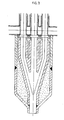
- Fig. 2 illustrates the wye in more detail.
- the connector 2 diverges, with a relatively small angle of divergence, into the two branches 3.
- the angle is selected to be small in order to avoid any abrupt changes in the direction of flow of the gas which could cause a pressure drop, and to make the structure compact. Suitably it may be, as measured between the central axes of the diverging branches, see the arrows 14, about 20° to about 40°, preferably about 30°.
- the branches straighten out and become substantially parallel in their downstream portions 5. This straightening is employed to confine erosion to the branches of the wye where an erosion allowance can be provided in the wall thickness. If the branches were not straightened prior to the gas entering the exchanger tubes, coke that miqht be contained in the gas would impinge on the thin walls of the exchanger cooling tube and erode a hole through the tube in a relatively short time.
- a baffle 6,formed by the intersection of the branches of the wye, is axially located to avoid or minimize expansion of the cross-sectional area of the flow path of the gas.
- the area at the line A-A is about the same as at the line B-B, for example 1870 mm 2
- the connector has already divided into two branches of roughly half said area each, for example 924 mm 2 .
- the ratio, R of the sum of the cross-sectional areas of the branches to the cross-sectional area of the connector is roughly 1:1, e.g., .988. This ratio achieves substantially constant gas velocity throughout the wye.
- the cooling tubes are sized to match or approximate the areas of the respective wye branches, and in this illustration may be, for example, about 924 mm2.
- the benefits of the invention can also be obtained to a large extent when R is greater than 1:1, up to about 2:1.
- the cracked gas flows directly from the branches of the wye to the respective cooling tubes. There is no dead flow area such as a tube sheet in its flow path and' therefore heavy ends in the cracked gas will remain suspended and not lay down as coke, blocking the flow area to the cooling tubes.
- the portions 5 of the wye, at their downstream ends, are not attached to the respective cooling tubes 4 but each is spaced from the cooling tube by an expansion gap 7 and held in position by a collar 8.
- the reducer is welded to the distributor 2 and to the oval header 23 as shown to prevent leakage of gasinto the atmosphere.
- the use of a reducer minimizes the thermal gradient and therefore reduces the thermal stress.
- a reducer has a variable cross-sectional area and diameter.
- the larger diameter end 11 of the reducer has more insulation 12 between its wall and the hot internal "Y" fitting than the small diameter end 13.
- the small diameter end which operates at the hottest temperature expands or grows thermally approximately the same radial distance as the cooler, large diameter end. Since both ends of the reducer thermally grow approximately the same amount, thermal stresses are minimized.
- the "Y" piece distributor 2 which conducts the hot cracked gas to the cold exchanger tubes operates at the same temperature as the hot cracked gas.
- the "Y” piece is not physically attached to the cold exchanger tubes, and, therefore, there is no sharp temperature gradient and no thermal stress at this point. Rather, there is a thermal expansion gap 7 between the portions 5 of the "Y" and the exchanger cooling tubes 4 to permit unrestricted expansion of the hot branches of the "Y". Since there is a thermal expansion gap provided, the walls of the reducer 10 act as the pressure-containing member rather than the "Y" distributor.
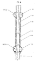
- Fig. 4 illustrates a single heat exchange tube which is in fluid flow communication with one branch of a wye.
- the downstream portion 5 of the branch is fitted to the cooling unit 20 so that gas can flow through the inner tube 21 which is jacketed by the outer shell 22.
- Water is passed via a header or plenum chamber 23 into the annular enclosure 24 between the tube-in-tube arrangement 21-22, takes up heat from the hot cracked gas and leaves as high pressure steam through header 25.
- the furnace will be equipped with a large number of such transfer line heat exchanger units.
- the units may be located at the top or at the bottom of the furnace and, in either case, gas flow may be upflow or downflow.
- Cooling tubes 27 feet long are required to cool the furnace effluent from 1573°F (856°C) to 662 0 F (350°C).
- the preferred outlet temperatures are above 900°F (482°C) which requires only 13- feet-long tubes.
- the same 27-feet- long exchanger tube may be used to cool the effluent to 720°F (382°C).
- Table I summarizes comparative data as between a conventional (expansion chamber) TLE and the present invention, for naphtha cracking.
- the total pressure drop is given from the fired outlet to a point downstream of the outlet collection manifold or outlet head of the TLE.
- the unfired residence time is measured from just outside the furnace fire box to the inlet of the cooling tubes. It can thus be seen that if the present invention is used rather than the conventional TLE, 0.75 wt.% more ethylene is produced.
- the I.D. of the distributor was 50.8 mm and of each branch of the wye was 43 mm.
- the total pressure drop is approximately 1.9 psi from the fired outlet to a point downstream of the outlet collection manifold for the TLE cooling tubes.
- the distributor is a tube of the same diameter as the furnace radiant coil connected to it, 1.85 inch I.D.
- the tube splits into two branches, each having a 1.69 inch I.D. and each leading into a cooling tube of the same diameter.
- the ratio, R equals 1.67.
- the cracked gas effluent is cooled in this unit from 1600°F to 998°F in cooling tubes 10.5 feet long. Total pressure drop is approximately 1.6 psi from the fired outlet to a point downstream of the cooling tubes.
- the present invention therefore achieves close coupling of the TLE cooling tubes to the radiant coils .of the furnace. Elimination of the collection manifold of numerous radiant coils and the TLE inlet chamber of the flared type, minimizes turbulence and recirculation of cracked gases between fired outlet and TLE cooling tubes. Thus, unfired residence time is reduced. These factors reduce non-selective cracking and subsequent coking in the unit. Smaller pressure drop decreases hydrocarbon partial pressure in the radiant coils and improves selectivity to ethylene. Operation without prequench upstream of the unit is permissible for gas crack-, ing at high conversions. The elimination of prequench increases the furnace's thermal efficiency by producing more steam in the TLE due to higher TLE inlet temperature. A prequench system has a 1200°F inlet whereas the close-coupled TLE system has about a 1600°F inlet. Thus, the invention has substantial thermal efficiency advantages and achieves valuable yield credits.
- tri-piece as used herein is meant to be included within the scope of the term “wye” in so far as it may be considered as a “wye” having an additional diverging branch.
Landscapes
- Engineering & Computer Science (AREA)
- Thermal Sciences (AREA)
- Physics & Mathematics (AREA)
- Chemical & Material Sciences (AREA)
- Oil, Petroleum & Natural Gas (AREA)
- Mechanical Engineering (AREA)
- General Engineering & Computer Science (AREA)
- Chemical Kinetics & Catalysis (AREA)
- General Chemical & Material Sciences (AREA)
- Organic Chemistry (AREA)
- Production Of Liquid Hydrocarbon Mixture For Refining Petroleum (AREA)
- Heat-Exchange Devices With Radiators And Conduit Assemblies (AREA)
- Details Of Heat-Exchange And Heat-Transfer (AREA)
Applications Claiming Priority (2)
| Application Number | Priority Date | Filing Date | Title |
|---|---|---|---|
| US359197 | 1982-03-18 | ||
| US06/359,197 US4457364A (en) | 1982-03-18 | 1982-03-18 | Close-coupled transfer line heat exchanger unit |
Publications (3)
| Publication Number | Publication Date |
|---|---|
| EP0089742A2 true EP0089742A2 (fr) | 1983-09-28 |
| EP0089742A3 EP0089742A3 (en) | 1984-04-04 |
| EP0089742B1 EP0089742B1 (fr) | 1987-01-14 |
Family
ID=23412743
Family Applications (1)
| Application Number | Title | Priority Date | Filing Date |
|---|---|---|---|
| EP83300758A Expired EP0089742B1 (fr) | 1982-03-18 | 1983-02-15 | Disposition étroite d'une unité d'entrée pour un échangeur de chaleur d'une conduite de transfert |
Country Status (4)
| Country | Link |
|---|---|
| US (1) | US4457364A (fr) |
| EP (1) | EP0089742B1 (fr) |
| JP (1) | JPS58173388A (fr) |
| DE (1) | DE3369185D1 (fr) |
Cited By (3)
| Publication number | Priority date | Publication date | Assignee | Title |
|---|---|---|---|---|
| US4454839A (en) * | 1982-08-02 | 1984-06-19 | Exxon Research & Engineering Co. | Furnace |
| EP0205205A1 (fr) * | 1985-05-28 | 1986-12-17 | Dow Chemical (Nederland) B.V. | Refroidisseur de conduit de transfert |
| WO1995032263A1 (fr) * | 1994-05-24 | 1995-11-30 | Abb Lummus Global Inc. | Refroidisseur rapide |
Families Citing this family (38)
| Publication number | Priority date | Publication date | Assignee | Title |
|---|---|---|---|---|
| US4614229A (en) * | 1983-06-20 | 1986-09-30 | Exxon Research & Engineering Co. | Method and apparatus for efficient recovery of heat from hot gases that tend to foul heat exchanger tubes |
| NO160469C (no) * | 1985-05-31 | 1994-09-23 | Norske Stats Oljeselskap | Y-formet koblingsstykke for sammenkobling av væske-og/eller gassförende rörledninger. |
| FR2584733B1 (fr) * | 1985-07-12 | 1987-11-13 | Inst Francais Du Petrole | Procede ameliore de vapocraquage d'hydrocarbures |
| DE3541887A1 (de) * | 1985-11-27 | 1987-06-04 | Krupp Koppers Gmbh | Waermetauscher zur kuehlung feststoffe enthaltender gase |
| US4785877A (en) * | 1986-05-16 | 1988-11-22 | Santa Fe Braun Inc. | Flow streamlining device for transfer line heat exchanges |
| DE3910630C3 (de) * | 1989-04-01 | 1998-12-24 | Borsig Babcock Ag | Verbindung eines ungekühlten Rohres mit einem gekühlten Rohr |
| US5271827A (en) * | 1990-11-29 | 1993-12-21 | Stone & Webster Engineering Corp. | Process for pyrolysis of hydrocarbons |
| US5409675A (en) * | 1994-04-22 | 1995-04-25 | Narayanan; Swami | Hydrocarbon pyrolysis reactor with reduced pressure drop and increased olefin yield and selectivity |
| US5690168A (en) * | 1996-11-04 | 1997-11-25 | The M. W. Kellogg Company | Quench exchanger |
| DE19847770A1 (de) * | 1998-10-16 | 2000-04-20 | Borsig Gmbh | Wärmetauscher mit einem Verbindungsstück |
| DE10064389A1 (de) * | 2000-12-21 | 2002-06-27 | Borsig Gmbh | Gaseintrittshaube |
| GB2386168A (en) * | 2002-02-13 | 2003-09-10 | Imp College Innovations Ltd | Pipe networks |
| US20030209469A1 (en) * | 2002-05-07 | 2003-11-13 | Westlake Technology Corporation | Cracking of hydrocarbons |
| US8524070B2 (en) * | 2005-07-08 | 2013-09-03 | Exxonmobil Chemical Patents Inc. | Method for processing hydrocarbon pyrolysis effluent |
| US7749372B2 (en) * | 2005-07-08 | 2010-07-06 | Exxonmobil Chemical Patents Inc. | Method for processing hydrocarbon pyrolysis effluent |
| US7718049B2 (en) * | 2005-07-08 | 2010-05-18 | Exxonmobil Chemical Patents Inc. | Method for processing hydrocarbon pyrolysis effluent |
| US7465388B2 (en) * | 2005-07-08 | 2008-12-16 | Exxonmobil Chemical Patents Inc. | Method for processing hydrocarbon pyrolysis effluent |
| US7674366B2 (en) * | 2005-07-08 | 2010-03-09 | Exxonmobil Chemical Patents Inc. | Method for processing hydrocarbon pyrolysis effluent |
| US7780843B2 (en) * | 2005-07-08 | 2010-08-24 | ExxonMobil Chemical Company Patents Inc. | Method for processing hydrocarbon pyrolysis effluent |
| US7763162B2 (en) * | 2005-07-08 | 2010-07-27 | Exxonmobil Chemical Patents Inc. | Method for processing hydrocarbon pyrolysis effluent |
| JP4640288B2 (ja) * | 2005-12-09 | 2011-03-02 | 株式会社デンソー | インタークーラ |
| US8701748B2 (en) * | 2006-02-17 | 2014-04-22 | Exxonmobil Chemical Patents Inc. | Outlet fitting for double pipe quench exchanger |
| JP2007229410A (ja) * | 2006-02-27 | 2007-09-13 | Yujiro Totsuka | 合格鵜雁鱒(うかります) |
| EP2069702A1 (fr) * | 2006-09-13 | 2009-06-17 | ExxonMobil Chemical Patents Inc. | Échangeur de trempe à surface augmentée sur le côté de traitement |
| EP2082010A4 (fr) * | 2006-09-28 | 2014-12-03 | Uop Llc | Procédé de production d'oléfines améliorée |
| US8074973B2 (en) * | 2007-10-02 | 2011-12-13 | Exxonmobil Chemical Patents Inc. | Method and apparatus for cooling pyrolysis effluent |
| EP2248581A1 (fr) | 2009-05-08 | 2010-11-10 | Total Petrochemicals Research Feluy | Processus de refroidissement des gaz émis d'un four |
| EP2408551A1 (fr) | 2009-03-17 | 2012-01-25 | Total Petrochemicals Research Feluy | Procédé pour le refroidissement brusque de l'effluent gazeux d'un four |
| EP2230009A1 (fr) | 2009-03-17 | 2010-09-22 | Total Petrochemicals Research Feluy | Processus de refroidissement des gaz émis d'un four |
| US8905335B1 (en) * | 2009-06-10 | 2014-12-09 | The United States Of America, As Represented By The Secretary Of The Navy | Casting nozzle with dimensional repeatability for viscous liquid dispensing |
| JP5738781B2 (ja) * | 2012-02-10 | 2015-06-24 | ダイキン工業株式会社 | 空気調和装置 |
| US9381787B2 (en) * | 2012-10-26 | 2016-07-05 | Hamilton Sundstrand Corporation | Generally wye shaped elbow for cabin air flow system |
| US9897244B1 (en) * | 2015-04-27 | 2018-02-20 | Darel W. Duvall | Grout reinforced piggable pipeline connector |
| JP2017145793A (ja) * | 2016-02-19 | 2017-08-24 | 富士通株式会社 | 冷却装置及び電子機器 |
| CN106855367B (zh) * | 2017-02-28 | 2024-01-26 | 郑州大学 | 具有分布性出入口的管壳式换热器 |
| CN106679467B (zh) * | 2017-02-28 | 2019-04-05 | 郑州大学 | 具有外接管箱的管壳式换热器 |
| IT201800004827A1 (it) | 2018-04-24 | 2019-10-24 | Scambiatore di calore a doppio tubo e relativo metodo di fabbricazione | |
| US20220119716A1 (en) * | 2020-10-15 | 2022-04-21 | Technip Process Technology, Inc. | Hybrid ethylene cracking furnace |
Citations (1)
| Publication number | Priority date | Publication date | Assignee | Title |
|---|---|---|---|---|
| FR1433702A (fr) * | 1964-04-21 | 1966-04-01 | Basf Ag | Procédé pour la production d'oléfines, en particulier d'éthylène, par craquage thermique d'hydrocarbures |
Family Cites Families (18)
| Publication number | Priority date | Publication date | Assignee | Title |
|---|---|---|---|---|
| US2082403A (en) * | 1936-08-06 | 1937-06-01 | Larkin Refrigerating Corp | Refrigerant distributor head |
| US2762635A (en) * | 1951-02-15 | 1956-09-11 | Babcock & Wilcox Co | Tube and header connections |
| US3421781A (en) * | 1964-08-21 | 1969-01-14 | Us Army | Transition section having a constant cross sectional area |
| DE1543156A1 (de) * | 1964-11-05 | 1969-07-31 | Lummus Co | Verfahren zur Erzeugung von AEthylen |
| US3357485A (en) * | 1965-04-21 | 1967-12-12 | Lummus Co | Cooler inlet device |
| US3910347A (en) * | 1966-06-13 | 1975-10-07 | Stone & Webster Eng Corp | Cooling apparatus and process |
| US3449212A (en) * | 1967-01-09 | 1969-06-10 | Lummus Co | Cyclonic cracking vapor heat exchanger inlet for solids removal |
| US3456719A (en) * | 1967-10-03 | 1969-07-22 | Lummus Co | Transfer line heat exchanger |
| US3552487A (en) * | 1967-11-29 | 1971-01-05 | Idemitsu Petrochemical Co | Quenching apparatus for use with thermal cracking system |
| US3574781A (en) * | 1968-02-14 | 1971-04-13 | Atlantic Richfield Co | Transition section for ethylene production unit |
| US3583476A (en) * | 1969-02-27 | 1971-06-08 | Stone & Webster Eng Corp | Gas cooling apparatus and process |
| DE1910105C3 (de) * | 1969-02-28 | 1978-09-14 | Bayer Ag, 5090 Leverkusen | Verfahren zur Herstellung von Chlormethylestern a,ß-ungesättigter Monocarbonsäuren |
| US3671198A (en) * | 1970-06-15 | 1972-06-20 | Pullman Inc | Cracking furnace having thin straight single pass reaction tubes |
| JPS4811682B1 (fr) * | 1970-12-29 | 1973-04-14 | ||
| US4151217A (en) * | 1972-07-04 | 1979-04-24 | Mitsubishi Jukogyo Kabushiki Kaisha | Method of cooling cracked gases of low boiling hydrocarbons |
| US4078292A (en) * | 1975-07-22 | 1978-03-14 | Allied Chemical Corporation | Transfer line exchanger inlet cone |
| US4097544A (en) * | 1977-04-25 | 1978-06-27 | Standard Oil Company | System for steam-cracking hydrocarbons and transfer-line exchanger therefor |
| US4192658A (en) * | 1978-07-03 | 1980-03-11 | Atlantic Richfield Company | Pipeline flame arrestor |
-
1982
- 1982-03-18 US US06/359,197 patent/US4457364A/en not_active Expired - Lifetime
-
1983
- 1983-02-15 EP EP83300758A patent/EP0089742B1/fr not_active Expired
- 1983-02-15 DE DE8383300758T patent/DE3369185D1/de not_active Expired
- 1983-03-18 JP JP58045853A patent/JPS58173388A/ja active Granted
Patent Citations (1)
| Publication number | Priority date | Publication date | Assignee | Title |
|---|---|---|---|---|
| FR1433702A (fr) * | 1964-04-21 | 1966-04-01 | Basf Ag | Procédé pour la production d'oléfines, en particulier d'éthylène, par craquage thermique d'hydrocarbures |
Cited By (3)
| Publication number | Priority date | Publication date | Assignee | Title |
|---|---|---|---|---|
| US4454839A (en) * | 1982-08-02 | 1984-06-19 | Exxon Research & Engineering Co. | Furnace |
| EP0205205A1 (fr) * | 1985-05-28 | 1986-12-17 | Dow Chemical (Nederland) B.V. | Refroidisseur de conduit de transfert |
| WO1995032263A1 (fr) * | 1994-05-24 | 1995-11-30 | Abb Lummus Global Inc. | Refroidisseur rapide |
Also Published As
| Publication number | Publication date |
|---|---|
| US4457364A (en) | 1984-07-03 |
| JPS58173388A (ja) | 1983-10-12 |
| JPH0420035B2 (fr) | 1992-03-31 |
| DE3369185D1 (en) | 1987-02-19 |
| EP0089742B1 (fr) | 1987-01-14 |
| EP0089742A3 (en) | 1984-04-04 |
Similar Documents
| Publication | Publication Date | Title |
|---|---|---|
| EP0089742B1 (fr) | Disposition étroite d'une unité d'entrée pour un échangeur de chaleur d'une conduite de transfert | |
| KR100525879B1 (ko) | 공정 유체 가열용 가열 장치 및 올레핀의 제조 방법 | |
| AU649532B2 (en) | Thermal cracking furnace and process | |
| CA2663065C (fr) | Echangeur de trempe a surface augmentee sur le cote de traitement | |
| JPS5870834A (ja) | 曲り/ワンパス管を有する改良炉 | |
| IL27808A (en) | Heating apparatus and process | |
| US3910347A (en) | Cooling apparatus and process | |
| US4397740A (en) | Method and apparatus for cooling thermally cracked hydrocarbon gases | |
| JPH04290836A (ja) | 炭化水素類の熱分解のための方法及び装置 | |
| EP1009783B1 (fr) | Refroidisseur par trempe | |
| US5427655A (en) | High capacity rapid quench boiler | |
| US5031692A (en) | Heat exchanger for cooling cracked gas | |
| EP2248581A1 (fr) | Processus de refroidissement des gaz émis d'un four | |
| CA1219254A (fr) | Echangeur de chaleur a ligne de transfert en couplage serre | |
| US20120060727A1 (en) | Process for quenching the effluent gas of a furnace | |
| EP2230009A1 (fr) | Processus de refroidissement des gaz émis d'un four | |
| RU2174141C2 (ru) | Устройство для подвода крекинг-газа из змеевика крекинг-печи | |
| MXPA99011425A (en) | Pyrolysis furnace with an internally finned u-shaped radiant coil |
Legal Events
| Date | Code | Title | Description |
|---|---|---|---|
| PUAI | Public reference made under article 153(3) epc to a published international application that has entered the european phase |
Free format text: ORIGINAL CODE: 0009012 |
|
| 17P | Request for examination filed |
Effective date: 19830224 |
|
| AK | Designated contracting states |
Designated state(s): DE FR GB IT NL |
|
| PUAL | Search report despatched |
Free format text: ORIGINAL CODE: 0009013 |
|
| AK | Designated contracting states |
Designated state(s): DE FR GB IT NL |
|
| GRAA | (expected) grant |
Free format text: ORIGINAL CODE: 0009210 |
|
| ITF | It: translation for a ep patent filed |
Owner name: BARZANO' E ZANARDO MILANO S.P.A. |
|
| AK | Designated contracting states |
Kind code of ref document: B1 Designated state(s): DE FR GB IT NL |
|
| REF | Corresponds to: |
Ref document number: 3369185 Country of ref document: DE Date of ref document: 19870219 |
|
| ET | Fr: translation filed | ||
| PLBE | No opposition filed within time limit |
Free format text: ORIGINAL CODE: 0009261 |
|
| STAA | Information on the status of an ep patent application or granted ep patent |
Free format text: STATUS: NO OPPOSITION FILED WITHIN TIME LIMIT |
|
| 26N | No opposition filed | ||
| ITTA | It: last paid annual fee | ||
| PGFP | Annual fee paid to national office [announced via postgrant information from national office to epo] |
Ref country code: NL Payment date: 20011214 Year of fee payment: 20 |
|
| REG | Reference to a national code |
Ref country code: GB Ref legal event code: IF02 |
|
| PGFP | Annual fee paid to national office [announced via postgrant information from national office to epo] |
Ref country code: GB Payment date: 20020108 Year of fee payment: 20 |
|
| PGFP | Annual fee paid to national office [announced via postgrant information from national office to epo] |
Ref country code: FR Payment date: 20020131 Year of fee payment: 20 |
|
| PGFP | Annual fee paid to national office [announced via postgrant information from national office to epo] |
Ref country code: DE Payment date: 20020228 Year of fee payment: 20 |
|
| PG25 | Lapsed in a contracting state [announced via postgrant information from national office to epo] |
Ref country code: GB Free format text: LAPSE BECAUSE OF EXPIRATION OF PROTECTION Effective date: 20030214 |
|
| PG25 | Lapsed in a contracting state [announced via postgrant information from national office to epo] |
Ref country code: NL Free format text: LAPSE BECAUSE OF EXPIRATION OF PROTECTION Effective date: 20030215 |
|
| REG | Reference to a national code |
Ref country code: GB Ref legal event code: PE20 Effective date: 20030214 |
|
| NLV7 | Nl: ceased due to reaching the maximum lifetime of a patent |
Effective date: 20030215 |