EP0089416B1 - Maintaining hydrostatic system control pressure - Google Patents
Maintaining hydrostatic system control pressure Download PDFInfo
- Publication number
- EP0089416B1 EP0089416B1 EP82111739A EP82111739A EP0089416B1 EP 0089416 B1 EP0089416 B1 EP 0089416B1 EP 82111739 A EP82111739 A EP 82111739A EP 82111739 A EP82111739 A EP 82111739A EP 0089416 B1 EP0089416 B1 EP 0089416B1
- Authority
- EP
- European Patent Office
- Prior art keywords
- fluid
- high pressure
- system control
- pump
- conduit
- Prior art date
- Legal status (The legal status is an assumption and is not a legal conclusion. Google has not performed a legal analysis and makes no representation as to the accuracy of the status listed.)
- Expired
Links
- 230000002706 hydrostatic effect Effects 0.000 title claims description 17
- 239000012530 fluid Substances 0.000 claims description 54
- 230000005540 biological transmission Effects 0.000 claims description 21
- 238000006073 displacement reaction Methods 0.000 claims description 6
- 230000000903 blocking effect Effects 0.000 claims description 3
- 230000001419 dependent effect Effects 0.000 claims description 2
- 238000001514 detection method Methods 0.000 description 2
- 238000010276 construction Methods 0.000 description 1
- 230000003472 neutralizing effect Effects 0.000 description 1
- 230000000135 prohibitive effect Effects 0.000 description 1
- 230000000007 visual effect Effects 0.000 description 1
Images
Classifications
-
- F—MECHANICAL ENGINEERING; LIGHTING; HEATING; WEAPONS; BLASTING
- F17—STORING OR DISTRIBUTING GASES OR LIQUIDS
- F17D—PIPE-LINE SYSTEMS; PIPE-LINES
- F17D5/00—Protection or supervision of installations
- F17D5/02—Preventing, monitoring, or locating loss
- F17D5/04—Preventing, monitoring, or locating loss by means of a signalling fluid enclosed in a double wall
-
- F—MECHANICAL ENGINEERING; LIGHTING; HEATING; WEAPONS; BLASTING
- F16—ENGINEERING ELEMENTS AND UNITS; GENERAL MEASURES FOR PRODUCING AND MAINTAINING EFFECTIVE FUNCTIONING OF MACHINES OR INSTALLATIONS; THERMAL INSULATION IN GENERAL
- F16H—GEARING
- F16H39/00—Rotary fluid gearing using pumps and motors of the volumetric type, i.e. passing a predetermined volume of fluid per revolution
- F16H39/02—Rotary fluid gearing using pumps and motors of the volumetric type, i.e. passing a predetermined volume of fluid per revolution with liquid motors at a distance from liquid pumps
Definitions
- This invention relates generally to hydrostatic transmission controls for controlling fluid from a pump to a motor in a continuous circuit and more particularly to such a system which prevents the loss of system control and fluid loss upon rupture of one of the pressure conduits connecting the pump and motor.
- Hydrostatic transmissions for use in a vehicle drive normally have a pump and a motor connected by first and second conduits in a continuous fluid circuit.
- the pump and/or motor displacement is controlled by a system control that requires a minimum pressure level to operate.
- These systems have a control pump which supplies fluid to the system control at the minimum pressure level and simultaneously supplies make-up fluid to the first and second conduits at the same minimum pressure level.
- US-A-35 28 243 can be interpreted as disclosing a known arrangement in accordance with the pre-characterizing part of claim 1.
- GB-A-875 224 is concerned with crack detection in double-walled piping such as where an outer wall is disposed about a pressure conduit and a space is formed between the outer wall and the pressure conduit.
- the outer wall incorporates a pressure-responsive device permitting visual detection of a crack in the pressure conduit.
- the present invention is directed to a hydraulic transmission in accordance with claim 1.
- Preferred features of the invention are set out in the dependent claims.
- the problem of losing control pressure upon rupture of one of the high pressure conduits connecting the pump and motor is solved by providing a low pressure conduit disposed about the high pressure conduit connecting the pump and the motor and having a space between the high and low pressure conduits communicated to a control mechanism which limits the maximum pressure level in the space and also maintains a minimum control pressure to the system control.
- a control mechanism which limits the maximum pressure level in the space and also maintains a minimum control pressure to the system control.
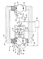
- a hydrostatic transmission is generally indicated by reference numeral 10 and includes a variable displacement pump 12 and a fluid motor 14 in continuous fluid communication with the pump 12.
- the pump 12 and the motor 14 each respectively have first and second conduit mounting brackets 16, 18 each being in fluid communication with fluid ports of the respective pump 12 or motor 14.
- a first high pressure conduit 20 connects one fluid port of the pump 12 to one fluid port of the motor 14 while a second high pressure conduit 22 connects the other fluid port of the pump to the other fluid port of the motor.
- a first low pressure conduit 24 is disposed about the first high pressure conduit 20 and is connected to the first conduit mounting bracket 16 on the pump 12 and the first conduit mounting bracket 16 on the motor 14.
- a second low pressure conduit 26 is disposed about the second high pressure conduit 22 and is connected to the second conduit mounting bracket 18 of the pump 12 and the second conduit mounting bracket 18 of the motor 14.
- Each of the first, second, third and fourth conduits are mounted to the respective mounting brackets 16, 18 of the pump 12 and motor 14 by any conventional manner, such as pressing the conduits into the bore of the mounting bracket or bolting the conduits to the mounting brackets.
- a first space 28 is defined between the outside diameter of the first high pressure conduit 20 and the inside diameter of the first low pressure conduit 24.
- a second space 30 is defined between the outside diameter of the second high pressure conduit 22 and the inside diameter of the second low pressure conduit 26.
- a means 32 is provided for controlling the pressure level in the first and second spaces 28, 30 to a predetermined maximum pressure level upon the rupture or other leakage failure of one of the first and second high pressure conduits 20, 22.
- the controlling means 32 includes a pressure relief valve 34 connected to the first and second spaces 28, 30 by conduits 36, 38 and to a tank 39 by a conduit 41.
- a source of pressurized fluid such as a control pump 40 receives fluid from a tank 39 and is connected to the first high pressure conduit 20 by conduits 42, 44.
- the control pump 40 is connected .to the second high pressure conduit 22 by the conduit 42 and a conduit 46.
- the conduits 44 and 46 each have a one-way check 47 located in the conduit to conduct fluid flow from the control pump 40 to the respective first and second high pressure conduits 20, 22 and to prevent reverse flow through the conduits 44 and 46.
- a system control relief valve 48 is connected to the conduit 42 by a conduit 49 and to the tank 39 by a conduit 51.
- a system control 50 is connected to the control pump 40 by a conduit 52.
- the variable displacement pump 12 has a pump control mechanism 54 connected to the system control by a signal control line 56.
- a reset valve 58 is connected to the conduits 44 and 46 by conduits 60 and 62, respectively.
- the reset valve 58 is in fluid communication with the system control 50 by a signal conduit 64.
- the pump 12 supplies pressurized fluid to the motor 14 through the high pressure conduit 20 to drive the motor in one direction.
- the exhaust flow from the motor 14 is returned to the inlet side of the pump 12 through the high pressure conduit 22.
- the motor 14 is turned in the opposite direction by reversing the flow from the pump 12 to the motor 14 through the high pressure conduit 22 and the exhaust flow returning from the motor 14 to the inlet of the pump 12 through the high pressure conduit 20.
- the direction of flow of the output of the pump 12 and the displacement of the pump is controlled by a signal being generated at the system control 50 and delivered to the pump control mechanism 54 by the signal control line 56.
- the control pump 40 delivers make-up fluid to the lower pressured one of the high pressure conduits 20, 22 at a predetermined minimum pressure level as established by the system control relief valve 48. Consequently, .the high pressure conduit that is being utilized as a fluid return to the motor will be maintained at the minimum pressure level. The high pressure in the other high pressure conduit will not affect operation of the control pump 40 because the pressurized flow is blocked at the respective one of the one-way checks 47.
- the control pump also supplies control fluid to the system control 50 at the same minimum pressure level as established by the system control relief valve 48.
- the system control 50 requires a predetermined minimum pressure level to provide the necessary control signal to the pump control mechanism 54.
- the reset valve 58 is a two-position valve movable between a first position at which the high pressure conduits 20 and 22 are in open fluid communication and a second position at which the fluid communication between the high pressure conduits 20 and 22 is blocked.
- the two-position valve 58 is movable to the first position in response to pressurized fluid in conduits 60 and 62 with the absence of the control signal from the system control 50.
- the two-position valve 58 is movable to the second, blocking position in response to a control signal received from the system control 50 acting on a pressure responsive chamber in the end of the two-position valve 58.
- the control signal from the system control 50 is sufficient to overcome a much higher pressure in either of conduits 60, 62 and still maintain the two-position valve 58 in the second blocking position.
- a two-position valve of this type is shown in the above noted U.S. Patent 3,528,243, Fig. 8 elements 203, 209 and 214.
- the fluid from the high pressure conduit 20 would immediately fill the first and second spaces 28, 30 since the pump 12 is supplying the fluid to the ruptured conduit until the pressure level drops below the pressure level being maintained by the control pump. At such time, the fluid from the control pump would continually provide fluid to finish filling the spaces 28, 30. Once the spaces 28, 30 are filled, the pressure level in the spaces 28,30 would be limited to the maximum pressure level as established by the relief valve 34 which is in fluid communication with the spaces 28, 30. All fluid passed across the relief valve 34 is directed to the tank 39. Tank 39 also serves as the supply tank for the control pump 40. Consequently, no fluid is lost from the system due to leakage or rupture in the high pressure conduits 20, 22.
- the control pump 40 would continue to provide fluid to the first or second high pressure conduits 20, 22 at the minimum pressure level established by the system control relief valve 48 while still maintaining the same fluid pressure supply to the system control 50. If the flow from the control pump 40 cannot replace the flow from the pump 12 being passed through the ruptured line 20 or associated leak point, the system control pressure will drop below the minimum pressure level required by the system control 50 thus neutralizing the transmission. The operator then moves his control level for travel in the opposite direction at which time the system control pressure will be re-established which will reset the transmission to allow full operation to continue in the opposite direction.
- the hydrostatic transmission can still be activated. This allows the vehicle to be operated in the opposite direction by providing a signal to the pump control mechanism 54 to change the pump's directional position which communicates pressurized fluid to high pressure conduit 22 thus causing the motor 14 to turn in the opposite direction.
- the fluid returning from the motor 14 would still be available to the inlet of the pump 12 even though the high pressure conduit 20 has ruptured since the spaces 28, 30 are filled with fluid at the minimum pressure level established by the system control relief valve 48. If the pressure level in the return high pressure conduit 20 increases due to an overrunning condition of the motor 14, the relief valve 34 would control the maximum pressure level in the spaces 28, 30 by conducting bypass fluid to the common tank 39 to ensure that the first and second low pressure conduits 24, 26 would not rupture.
- the structure of the present invention provides an improved hydrostatic transmission that allows the vehicle to be movable in an opposite direction upon the failure of the high pressure conduit providing fluid to the motor in the one direction.
- This arrangement maintains a pressurized control fluid to the system control that is required to operate the hydrostatic transmission while not requiring the addition of an outer conduit that has to withstand the high pressure contained within the inner conduit upon rupture of the inner conduit. Due to the physical size required of the outer conduit and the high pressure contained within the inner conduit, construction of such a conduit would be prohibitive.
- unexpected rupture of a high pressure line will not totally disable the vehicle but would allow the vehicle to be moved in the opposite direction. This allows the vehicle to be moved from the location the rupture occurred to a location that would enable easier service to replace the ruptured conduit or otherwise repair the leakage failure.
Landscapes
- Engineering & Computer Science (AREA)
- General Engineering & Computer Science (AREA)
- Mechanical Engineering (AREA)
- Control Of Fluid Gearings (AREA)
- Fluid-Pressure Circuits (AREA)
Applications Claiming Priority (2)
| Application Number | Priority Date | Filing Date | Title |
|---|---|---|---|
| US06/361,306 US4425758A (en) | 1982-03-24 | 1982-03-24 | Maintaining hydrostatic system control pressure |
| US361306 | 1989-06-05 |
Publications (2)
| Publication Number | Publication Date |
|---|---|
| EP0089416A1 EP0089416A1 (en) | 1983-09-28 |
| EP0089416B1 true EP0089416B1 (en) | 1986-11-26 |
Family
ID=23421505
Family Applications (1)
| Application Number | Title | Priority Date | Filing Date |
|---|---|---|---|
| EP82111739A Expired EP0089416B1 (en) | 1982-03-24 | 1982-12-17 | Maintaining hydrostatic system control pressure |
Country Status (5)
| Country | Link |
|---|---|
| US (1) | US4425758A (cg-RX-API-DMAC7.html) |
| EP (1) | EP0089416B1 (cg-RX-API-DMAC7.html) |
| JP (1) | JPS58163859A (cg-RX-API-DMAC7.html) |
| CA (1) | CA1173723A (cg-RX-API-DMAC7.html) |
| DE (1) | DE3274492D1 (cg-RX-API-DMAC7.html) |
Families Citing this family (4)
| Publication number | Priority date | Publication date | Assignee | Title |
|---|---|---|---|---|
| US4879501A (en) * | 1982-12-10 | 1989-11-07 | Commercial Shearing, Inc. | Constant speed hydrostatic drive system |
| JP2761283B2 (ja) * | 1990-07-02 | 1998-06-04 | 本田技研工業株式会社 | 油圧変速装置 |
| DE4422424A1 (de) * | 1994-06-28 | 1996-01-04 | Schloemann Siemag Ag | Hydrostatische Getriebe |
| DE102005058776B4 (de) * | 2005-12-09 | 2018-03-01 | Zf Friedrichshafen Ag | Vorrichtung zum Steuern und/oder Regeln eines hydraulisch betätigbaren Schaltelementes einer Getriebeeinrichtung und Getriebeeinrichtung |
Family Cites Families (13)
| Publication number | Priority date | Publication date | Assignee | Title |
|---|---|---|---|---|
| DE462273C (de) | 1928-07-07 | Deckel Friedrich | Brennstoffdruckleitung fuer Einspritzvorrichtungen von Verbrennungskraftmaschinen | |
| US2838074A (en) | 1954-12-06 | 1958-06-10 | Borg Warner | Fluid pressure hose |
| GB875224A (en) * | 1957-06-25 | 1961-08-16 | Bristol Aircraft Ltd | Improvements in piping systems |
| GB1039515A (en) | 1962-07-24 | 1966-08-17 | Power Aux Ies Ltd | Improvements in or relating to flexible pressure tubes and ducts |
| US3526288A (en) * | 1967-06-14 | 1970-09-01 | Caterpillar Tractor Co | Hydrostatic transmission control system |
| US3528243A (en) | 1967-06-14 | 1970-09-15 | Caterpillar Tractor Co | Relief and replenish package for a hydrostatic transmission |
| US3526245A (en) * | 1967-06-14 | 1970-09-01 | Caterpillar Tractor Co | Valve for hydrostatic transmission control system |
| DE2114803A1 (de) * | 1971-03-26 | 1972-09-28 | Beham H | Kraftübertragungsvorrichtung |
| US4062376A (en) * | 1975-09-05 | 1977-12-13 | Mcgrath Robert L | Service connection between a main and a meter in a building and method of and equipment for installing the same |
| IT1070771B (it) * | 1976-02-02 | 1985-04-02 | Ind Veneta Gomma Colbachini Sp | Tubazione flessibile con una o piu intercapedini particolarmente adatta al carico scarico di navi petroliere |
| DE2634963A1 (de) * | 1976-08-04 | 1978-02-09 | Hartmut Klein | Schutzeinrichtung, insbesondere wasserschadenschutzeinrichtung |
| US4149568A (en) | 1977-12-07 | 1979-04-17 | Caterpillar Tractor Co. | Double walled fuel line |
| US4265235A (en) | 1979-05-11 | 1981-05-05 | Fukunaga Atsuo F | Anesthetic system |
-
1982
- 1982-03-24 US US06/361,306 patent/US4425758A/en not_active Expired - Fee Related
- 1982-12-17 DE DE8282111739T patent/DE3274492D1/de not_active Expired
- 1982-12-17 EP EP82111739A patent/EP0089416B1/en not_active Expired
- 1982-12-20 CA CA000418111A patent/CA1173723A/en not_active Expired
-
1983
- 1983-02-14 JP JP58022675A patent/JPS58163859A/ja active Granted
Also Published As
| Publication number | Publication date |
|---|---|
| CA1173723A (en) | 1984-09-04 |
| DE3274492D1 (en) | 1987-01-15 |
| JPS58163859A (ja) | 1983-09-28 |
| EP0089416A1 (en) | 1983-09-28 |
| US4425758A (en) | 1984-01-17 |
| JPH0313452B2 (cg-RX-API-DMAC7.html) | 1991-02-22 |
Similar Documents
| Publication | Publication Date | Title |
|---|---|---|
| US4337620A (en) | Load sensing hydraulic system | |
| EP0249154B1 (en) | Hydraulic pressure system | |
| US3994133A (en) | Automatic control device for the distribution of hydraulic fluid between two hydraulic circuits | |
| US3948049A (en) | Dual motor hydrostatic drive system | |
| US4470260A (en) | Open center load sensing hydraulic system | |
| US7464545B2 (en) | Hydraulic system and work machine comprising such a system | |
| US7200993B2 (en) | Electro-hydraulic steering control system | |
| US4400938A (en) | Hydraulic fluid feeding device for power steering device | |
| US6474063B2 (en) | Travel motor hydraulic control system for a construction machine | |
| US3935918A (en) | Dual source hydraulic steering system | |
| JPH045841B2 (cg-RX-API-DMAC7.html) | ||
| JPH0345471A (ja) | 全油圧式ステアリングシステムのハンドル位置補正装置 | |
| US4953445A (en) | Control device with failure detection centering for a double-acting hydraulic jack | |
| US4955445A (en) | Hydrostatic auxiliary power steering mechanism for motor vehicles | |
| US4011920A (en) | Synchronized vehicle fluid drive system | |
| EP0089416B1 (en) | Maintaining hydrostatic system control pressure | |
| CN1316167C (zh) | 在开式回路系统泵中自动遥控压力补偿装置 | |
| US4463558A (en) | Load sensing hydraulic system | |
| EP0404946B1 (en) | Hydraulic circuit device of construction vehicle | |
| US6131687A (en) | Process for actuating the steering cylinders of mobile plant and steering system therefor | |
| JPH01314668A (ja) | 静液圧ステアリング装置 | |
| US3696613A (en) | Hydraulic steering system having auxiliary power source | |
| CA2062778A1 (en) | Pilot control circuit for load sensing hydraulic systems | |
| EP4311740B1 (en) | Steering system | |
| US6595314B2 (en) | Hydraulic steering system, for an articulated vehicle with wheel steering |
Legal Events
| Date | Code | Title | Description |
|---|---|---|---|
| PUAI | Public reference made under article 153(3) epc to a published international application that has entered the european phase |
Free format text: ORIGINAL CODE: 0009012 |
|
| AK | Designated contracting states |
Designated state(s): DE FR GB IT |
|
| 17P | Request for examination filed |
Effective date: 19840314 |
|
| GRAA | (expected) grant |
Free format text: ORIGINAL CODE: 0009210 |
|
| RAP1 | Party data changed (applicant data changed or rights of an application transferred) |
Owner name: CATERPILLAR INC. |
|
| AK | Designated contracting states |
Kind code of ref document: B1 Designated state(s): DE FR GB IT |
|
| ITF | It: translation for a ep patent filed | ||
| REF | Corresponds to: |
Ref document number: 3274492 Country of ref document: DE Date of ref document: 19870115 |
|
| ET | Fr: translation filed | ||
| PLBE | No opposition filed within time limit |
Free format text: ORIGINAL CODE: 0009261 |
|
| STAA | Information on the status of an ep patent application or granted ep patent |
Free format text: STATUS: NO OPPOSITION FILED WITHIN TIME LIMIT |
|
| 26N | No opposition filed | ||
| PGFP | Annual fee paid to national office [announced via postgrant information from national office to epo] |
Ref country code: FR Payment date: 19911111 Year of fee payment: 10 |
|
| PGFP | Annual fee paid to national office [announced via postgrant information from national office to epo] |
Ref country code: GB Payment date: 19911118 Year of fee payment: 10 |
|
| PGFP | Annual fee paid to national office [announced via postgrant information from national office to epo] |
Ref country code: DE Payment date: 19911213 Year of fee payment: 10 |
|
| ITTA | It: last paid annual fee | ||
| PG25 | Lapsed in a contracting state [announced via postgrant information from national office to epo] |
Ref country code: GB Effective date: 19921217 |
|
| GBPC | Gb: european patent ceased through non-payment of renewal fee |
Effective date: 19921217 |
|
| PG25 | Lapsed in a contracting state [announced via postgrant information from national office to epo] |
Ref country code: FR Effective date: 19930831 |
|
| PG25 | Lapsed in a contracting state [announced via postgrant information from national office to epo] |
Ref country code: DE Effective date: 19930901 |
|
| REG | Reference to a national code |
Ref country code: FR Ref legal event code: ST |