EP0089342B1 - A lifting fork - Google Patents
A lifting fork Download PDFInfo
- Publication number
- EP0089342B1 EP0089342B1 EP82901319A EP82901319A EP0089342B1 EP 0089342 B1 EP0089342 B1 EP 0089342B1 EP 82901319 A EP82901319 A EP 82901319A EP 82901319 A EP82901319 A EP 82901319A EP 0089342 B1 EP0089342 B1 EP 0089342B1
- Authority
- EP
- European Patent Office
- Prior art keywords
- lifting
- shank
- fork
- forks
- connecting bar
- Prior art date
- Legal status (The legal status is an assumption and is not a legal conclusion. Google has not performed a legal analysis and makes no representation as to the accuracy of the status listed.)
- Expired
Links
- 230000036461 convulsion Effects 0.000 description 2
- 229910000831 Steel Inorganic materials 0.000 description 1
- 230000005484 gravity Effects 0.000 description 1
- 238000003780 insertion Methods 0.000 description 1
- 230000037431 insertion Effects 0.000 description 1
- 238000012986 modification Methods 0.000 description 1
- 230000004048 modification Effects 0.000 description 1
- 239000010959 steel Substances 0.000 description 1
Images


Classifications
-
- B—PERFORMING OPERATIONS; TRANSPORTING
- B66—HOISTING; LIFTING; HAULING
- B66C—CRANES; LOAD-ENGAGING ELEMENTS OR DEVICES FOR CRANES, CAPSTANS, WINCHES, OR TACKLES
- B66C1/00—Load-engaging elements or devices attached to lifting or lowering gear of cranes or adapted for connection therewith for transmitting lifting forces to articles or groups of articles
- B66C1/10—Load-engaging elements or devices attached to lifting or lowering gear of cranes or adapted for connection therewith for transmitting lifting forces to articles or groups of articles by mechanical means
- B66C1/22—Rigid members, e.g. L-shaped members, with parts engaging the under surface of the loads; Crane hooks
- B66C1/24—Single members engaging the loads from one side only
- B66C1/26—Single members engaging the loads from one side only with means for releasing the loads
Definitions
- the present invention refers to a lifting fork adapted to be suspended from a lifting member and which is substantially C-shaped, where the forks make one shank of the C while the other shank, the lifting shank, is adapted to receive a movable attachment means for the lifting member for transmitting a force to the lifting fork.
- the lifting member e.g. a lifting hook of a hoisting crane
- the lifting member can be attached to a loop or the like, which usually is displaceable along the lifting shank of the lifting fork for adjusting the point of action of the lifting member to the centre of gravity of the lifting fork in empty and loaded condition resp.
- the lifting fork will in this way be self- balancing and the shanks can be kept substantially horizontal in empty as well as in loaded condition, which facilitates the insertion of the shanks under the load and prevents the load from slipping off the shanks.
- the object of the invention is to avoid the above difficulties and to provide a lifting fork, the forks of which easily can be withdrawn from the load by means of the force from the hoisting crane even if the forks are jammed, e.g. owing to that the ground is uneven.
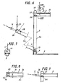
- the lifting fork 1 which is mainly used for goods loaded on loading stools is substantially C-shaped as seen from the side, the forks 2 making one shank of said C and the lifting shank 3 making the other shank.
- the lifting member 4, e.g. a hook, is intended to be attached to the lifting shank.
- the intermediate portion of the C viz the connecting bar 5 of the lifting fork 1, and the lifting shank 3 consist of a H-beam bent 90°, which at one end is attached to a square beam 6 extending across the forks 2 at their rear ends.
- the forks 2 are attached to said square beam.
- a link 7 is displaceable along the H-beam 3, on rollers 8 or sliding shoes, said link 7 being provided with an attachment means 11 for the lifting member 4, e.g. a hook of a hoisting crane.
- an eccentric 10 On each axle 9 of the rollers 8 there is arranged an eccentric 10 with a grooved surface gripping-the inside of the lifting shank 3, e.g. a grooved steel surface, when the link 7 is in its lifting position, i.e. vertical. At other positions of the link 7 the eccentric 10 is released from the lifting shank 3 and the link 7 can be displaced on the rollers 8.
- the point of action of the lifting force at the lifting fork is denoted A.
- a removable stop member 12 At the free end of the lifting shank 3 there is preferably arranged a removable stop member 12.
- the link 7 can freely be displaced from the lifting shank 3 down along the connecting bar 5 to a position close to the forks 2, at which the point of action A of the lifting force is moved to the same position, so that the forks by means of the hoisting crane easily can be withdrawn from the loading stool even if they are jammed.
- FIG. 4 and 5 there is shown another embodiment of the lifting fork 1, where the connecting bar 5 together with the lifting shank 3 is pivoted at its lower end about an axle 13.
- the attachment means of the lifting hook 4 consists of a yoke 14 gripping the lifting shank 3 and being displaceable along this.
- the connecting bar 5 can in upright position be locked to a locking arm 15, which is fixed to the forks 2 by way of the square beam 6. Locking is provided by means of a locking bar 16, which is axially displaceable within the connecting bar 5. Even when the locking bar 16 is retracted the connecting bar 5 is kept upright by means of a snap lock 18 cooperating with a recess 17 in the locking arm 15. A strong jerk backwards is required for pulling the connecting bar 5 out of this position and make it pivot backwards to the position shown in fig. 4.
- the position of the locking bar 16 is controlled by a two-armed lever 19 arranged in the lifting shank 3, the arm of the lever 19 facing the connecting bar 5 being spring-loaded 20 and acting upon a head 21 projecting from the locking bar 16.
- a shoulder 22 attached to the lifting shank 3 prevents the yoke 14 from being brought against the head 21 of the locking bar 16 by mistake.
- the yoke 14 In order to move the locking bar 16 out of its locking position the yoke 14 is displaced inwards along the lifting shank 3 past the shoulder 22 and under the head 21, which if a vertical lifting force is applied to the yoke 14 is pressed upwards against the action of the spring 20, at which the locking bar 16 is moved upwards.
- the yoke 14 When lifting the lifting fork empty the yoke 14 is located somewhere between the two end positions and in such a position the locking bar 16 is maintained in locking position by the spring 20.
- the connecting bar 5 can as described above together with the lifting shank 3 be pivoted backwards through an obliquely backwards directed jerk from the hoisting crane to the position shown in fig. 5, which shows a suitable position for withdrawing the forks from the loading stool, when this is not easily made in another way.
- the point of action A of the lifting force will in this position be at the axle 13.
- Exterior supports for the forks 2 are denoted with 23, said supports can consist of rollers.
- the connecting bar 5 consists of two parts, a fixed inner box girder 5a and an outer U-beam 5b, which at its lower end is pivoted about the axle 13 to the position shown with dash dotted lines in fig. 5.
- the axle 13 will also in this case be the point of action A of the lifting force when the outer U-beam 5b is pivoted backwards to the dash dotted position.
- the attachment means for the lifting hook 4 consists of a yoke 14, which is guided along the lifting shank 3 by a pair of flanges 24 projecting therefrom.
- the U-beam 5b is at its upper end provided with a hook 25 with a spring-loaded pawl 26.
- the lock is released by means of the yoke 14 when this is brought backwards and somewhat downwards, as is shown in fig. 9.
- the pawl 26 is returned and shuts up the yoke 14 in the hook 25 (shown with dash dotted lines in fig. 6).
- the pawl 26 is forced backwards again when it hits a pin 27 attached to the fixed box girder 5a and the pawl engages the pin 27.
- the yoke 14 can now be brought over to the lifting shank 3.
Landscapes
- Engineering & Computer Science (AREA)
- Mechanical Engineering (AREA)
- Load-Engaging Elements For Cranes (AREA)
- Jib Cranes (AREA)
- Polyesters Or Polycarbonates (AREA)
- Forklifts And Lifting Vehicles (AREA)
Priority Applications (1)
| Application Number | Priority Date | Filing Date | Title |
|---|---|---|---|
| AT82901319T ATE18659T1 (de) | 1981-04-27 | 1982-04-26 | Hebegabel. |
Applications Claiming Priority (2)
| Application Number | Priority Date | Filing Date | Title |
|---|---|---|---|
| SE8102640 | 1981-04-27 | ||
| SE8102640A SE429642B (sv) | 1981-04-27 | 1981-04-27 | Lyftgaffel |
Publications (2)
| Publication Number | Publication Date |
|---|---|
| EP0089342A1 EP0089342A1 (en) | 1983-09-28 |
| EP0089342B1 true EP0089342B1 (en) | 1986-03-19 |
Family
ID=20343684
Family Applications (1)
| Application Number | Title | Priority Date | Filing Date |
|---|---|---|---|
| EP82901319A Expired EP0089342B1 (en) | 1981-04-27 | 1982-04-26 | A lifting fork |
Country Status (8)
| Country | Link |
|---|---|
| US (1) | US4475758A (da) |
| EP (1) | EP0089342B1 (da) |
| DE (1) | DE3269937D1 (da) |
| DK (1) | DK153644C (da) |
| FI (1) | FI72102C (da) |
| NO (1) | NO152409C (da) |
| SE (1) | SE429642B (da) |
| WO (1) | WO1982003846A1 (da) |
Families Citing this family (10)
| Publication number | Priority date | Publication date | Assignee | Title |
|---|---|---|---|---|
| JPH10114135A (ja) * | 1996-10-12 | 1998-05-06 | Riso Kagaku Corp | 減圧式孔版印刷方法及び装置 |
| US6578892B2 (en) * | 2000-10-31 | 2003-06-17 | Valery Tsimmerman | Articulated lifting devices for lifting objects under overhangs |
| US6439632B1 (en) | 2001-01-02 | 2002-08-27 | Jeff Webber | Pallet lifting hook |
| US6817827B2 (en) * | 2003-01-23 | 2004-11-16 | Frank Targonski | Lifting apparatus with stabilizer |
| US8376432B1 (en) * | 2010-10-04 | 2013-02-19 | Hagler Systems, Inc. | Impeller jig |
| US8636312B2 (en) * | 2011-01-12 | 2014-01-28 | Eastall Precision Engineering Pty Ltd. | Lifting hook with backstop |
| US8622450B1 (en) | 2012-02-22 | 2014-01-07 | Carl Mengel | Cam hook truss lift system |
| US9440822B2 (en) * | 2014-11-24 | 2016-09-13 | Jorge Pulido | Wheel transporting assembly |
| RU2662478C1 (ru) * | 2017-09-18 | 2018-07-26 | Общество с ограниченной ответственностью "НПП СК МОСТ" | Способ демонтажа железобетонной плиты сооружения и грузозахватное устройство с эксцентриком для его осуществления |
| US20220089414A1 (en) * | 2020-09-24 | 2022-03-24 | Parmerit Inc. | Lifting and tilting device |
Family Cites Families (13)
| Publication number | Priority date | Publication date | Assignee | Title |
|---|---|---|---|---|
| US872651A (en) * | 1907-06-24 | 1907-12-03 | Ira Gordon | Hay and grain loader. |
| US993145A (en) * | 1910-04-12 | 1911-05-23 | Abner J Bradley | Manure-fork and lifting-derrick. |
| US1564652A (en) * | 1925-03-30 | 1925-12-08 | New York Brick Handling Corp | Dumping fork |
| GB275310A (en) * | 1926-05-03 | 1927-08-03 | Llewellyn Morris | Improvements in and relating to hay and like forks |
| US1745839A (en) * | 1927-06-07 | 1930-02-04 | New York Brick Handling Corp | Dumping fork |
| US1765765A (en) * | 1927-11-03 | 1930-06-24 | Lancaster Iron Works Inc | Brick-handling apparatus |
| US1811429A (en) * | 1928-06-16 | 1931-06-23 | Robert A Fontaine | Brick stack carrier |
| US1818728A (en) * | 1930-03-08 | 1931-08-11 | Arlington H Mallery | Brick handling mechanism |
| US2133557A (en) * | 1937-05-27 | 1938-10-18 | Mcneillie Charles | Article handling device |
| US2849253A (en) * | 1956-12-31 | 1958-08-26 | Bopp Mfg Inc | Self-balancing loadere fork |
| US2918322A (en) * | 1958-04-07 | 1959-12-22 | Bopp Mfg Inc | Loader |
| US3165344A (en) * | 1963-08-16 | 1965-01-12 | Ronald W Holder | Lifting hook with unloading link |
| SE326270B (da) * | 1967-06-29 | 1970-07-20 | B Johansson |
-
1981
- 1981-04-27 SE SE8102640A patent/SE429642B/sv not_active IP Right Cessation
-
1982
- 1982-04-26 DE DE8282901319T patent/DE3269937D1/de not_active Expired
- 1982-04-26 WO PCT/SE1982/000136 patent/WO1982003846A1/en not_active Ceased
- 1982-04-26 EP EP82901319A patent/EP0089342B1/en not_active Expired
- 1982-04-27 US US06/372,433 patent/US4475758A/en not_active Expired - Fee Related
- 1982-12-23 DK DK569482A patent/DK153644C/da not_active IP Right Cessation
- 1982-12-27 NO NO824368A patent/NO152409C/no unknown
-
1983
- 1983-05-27 FI FI831896A patent/FI72102C/fi not_active IP Right Cessation
Also Published As
| Publication number | Publication date |
|---|---|
| SE429642B (sv) | 1983-09-19 |
| FI72102B (fi) | 1986-12-31 |
| DK569482A (da) | 1982-12-23 |
| FI831896L (fi) | 1983-05-27 |
| FI72102C (fi) | 1987-04-13 |
| DK153644C (da) | 1988-12-19 |
| NO152409C (no) | 1985-09-25 |
| NO152409B (no) | 1985-06-17 |
| DK153644B (da) | 1988-08-08 |
| DE3269937D1 (en) | 1986-04-24 |
| US4475758A (en) | 1984-10-09 |
| FI831896A0 (fi) | 1983-05-27 |
| WO1982003846A1 (en) | 1982-11-11 |
| NO824368L (no) | 1982-12-27 |
| EP0089342A1 (en) | 1983-09-28 |
| SE8102640L (sv) | 1982-10-28 |
Similar Documents
| Publication | Publication Date | Title |
|---|---|---|
| EP0089342B1 (en) | A lifting fork | |
| US4460210A (en) | Lifting device | |
| US4925226A (en) | Manually operated cargo container hook apparatus | |
| GB2072741A (en) | Device for suspending from a crane or other hoist a prefabricated concrete block | |
| US3033605A (en) | Expansion-type grapple for lifting and carrying loads | |
| US4697788A (en) | Means for automatically releasing a jack system | |
| US5137115A (en) | Safety cage with improved latch mechanism | |
| US7032943B1 (en) | Apparatus with a locking mechanism for the latching and unlatching of a load | |
| US6089634A (en) | Safety lifting device | |
| US2360365A (en) | Steel plate lifting tongs | |
| US5433576A (en) | Low profile dolly and ramp assembly for a roll | |
| EP0160021B1 (en) | A device for lifting and handling objects | |
| US4537434A (en) | Adjustable self-releasing hook | |
| NL8103674A (nl) | Inrichting voor het dragen van een last met een beweegbaar ophangorgaan. | |
| GB2156312A (en) | Load handler | |
| US3510019A (en) | Device for handling drums in horizontal condition | |
| US3092414A (en) | Pile pulling tongs | |
| AU2007200211B1 (en) | A Quick Release Lifting Hook | |
| AT392770B (de) | Vorrichtung zur automatischen entsperrung von falltaschen bei lastaufnahmemitteln | |
| DE9112067U1 (de) | Handhabungsvorrichtung für Lagerkästen | |
| US4072324A (en) | Shear pin assembly for counterweights | |
| DE922486C (de) | Kranseilbahn | |
| DE2236320B2 (de) | Seilzuglaufkatzenpaar mit koppelbaren Unterflaschen | |
| JPH02239092A (ja) | シャックル | |
| DD226861B1 (de) | Lastgreif- und trageinrichhtung mit fernbedienbarer entsperrung |
Legal Events
| Date | Code | Title | Description |
|---|---|---|---|
| PUAI | Public reference made under article 153(3) epc to a published international application that has entered the european phase |
Free format text: ORIGINAL CODE: 0009012 |
|
| 17P | Request for examination filed |
Effective date: 19830524 |
|
| AK | Designated contracting states |
Designated state(s): AT BE CH DE FR GB LI NL |
|
| GRAA | (expected) grant |
Free format text: ORIGINAL CODE: 0009210 |
|
| AK | Designated contracting states |
Kind code of ref document: B1 Designated state(s): AT BE CH DE FR GB LI NL |
|
| REF | Corresponds to: |
Ref document number: 18659 Country of ref document: AT Date of ref document: 19860415 Kind code of ref document: T |
|
| REF | Corresponds to: |
Ref document number: 3269937 Country of ref document: DE Date of ref document: 19860424 |
|
| ET | Fr: translation filed | ||
| PLBE | No opposition filed within time limit |
Free format text: ORIGINAL CODE: 0009261 |
|
| STAA | Information on the status of an ep patent application or granted ep patent |
Free format text: STATUS: NO OPPOSITION FILED WITHIN TIME LIMIT |
|
| 26N | No opposition filed | ||
| PGFP | Annual fee paid to national office [announced via postgrant information from national office to epo] |
Ref country code: GB Payment date: 19930421 Year of fee payment: 12 |
|
| PGFP | Annual fee paid to national office [announced via postgrant information from national office to epo] |
Ref country code: FR Payment date: 19930422 Year of fee payment: 12 |
|
| PGFP | Annual fee paid to national office [announced via postgrant information from national office to epo] |
Ref country code: NL Payment date: 19930430 Year of fee payment: 12 |
|
| PGFP | Annual fee paid to national office [announced via postgrant information from national office to epo] |
Ref country code: BE Payment date: 19930512 Year of fee payment: 12 |
|
| PGFP | Annual fee paid to national office [announced via postgrant information from national office to epo] |
Ref country code: CH Payment date: 19930513 Year of fee payment: 12 |
|
| PGFP | Annual fee paid to national office [announced via postgrant information from national office to epo] |
Ref country code: DE Payment date: 19930519 Year of fee payment: 12 |
|
| PGFP | Annual fee paid to national office [announced via postgrant information from national office to epo] |
Ref country code: AT Payment date: 19930611 Year of fee payment: 12 |
|
| PG25 | Lapsed in a contracting state [announced via postgrant information from national office to epo] |
Ref country code: GB Effective date: 19940426 Ref country code: AT Effective date: 19940426 |
|
| PG25 | Lapsed in a contracting state [announced via postgrant information from national office to epo] |
Ref country code: LI Effective date: 19940430 Ref country code: CH Effective date: 19940430 Ref country code: BE Effective date: 19940430 |
|
| BERE | Be: lapsed |
Owner name: PAULSSON HJALMAR Effective date: 19940430 |
|
| PG25 | Lapsed in a contracting state [announced via postgrant information from national office to epo] |
Ref country code: NL Effective date: 19941101 |
|
| NLV4 | Nl: lapsed or anulled due to non-payment of the annual fee | ||
| GBPC | Gb: european patent ceased through non-payment of renewal fee |
Effective date: 19940426 |
|
| PG25 | Lapsed in a contracting state [announced via postgrant information from national office to epo] |
Ref country code: FR Effective date: 19941229 |
|
| REG | Reference to a national code |
Ref country code: CH Ref legal event code: PL |
|
| PG25 | Lapsed in a contracting state [announced via postgrant information from national office to epo] |
Ref country code: DE Effective date: 19950103 |
|
| REG | Reference to a national code |
Ref country code: FR Ref legal event code: ST |