EP0089341B1 - A sealing device for valves - Google Patents
A sealing device for valves Download PDFInfo
- Publication number
- EP0089341B1 EP0089341B1 EP82901315A EP82901315A EP0089341B1 EP 0089341 B1 EP0089341 B1 EP 0089341B1 EP 82901315 A EP82901315 A EP 82901315A EP 82901315 A EP82901315 A EP 82901315A EP 0089341 B1 EP0089341 B1 EP 0089341B1
- Authority
- EP
- European Patent Office
- Prior art keywords
- sealing
- valve
- engagement
- plane
- line
- Prior art date
- Legal status (The legal status is an assumption and is not a legal conclusion. Google has not performed a legal analysis and makes no representation as to the accuracy of the status listed.)
- Expired
Links
- 238000007789 sealing Methods 0.000 title claims abstract description 117
- 238000013461 design Methods 0.000 description 9
- 238000010276 construction Methods 0.000 description 5
- 230000001105 regulatory effect Effects 0.000 description 5
- 238000007493 shaping process Methods 0.000 description 5
- 238000005520 cutting process Methods 0.000 description 4
- 238000003754 machining Methods 0.000 description 4
- 238000004519 manufacturing process Methods 0.000 description 4
- 238000005259 measurement Methods 0.000 description 4
- 238000000034 method Methods 0.000 description 4
- 238000013459 approach Methods 0.000 description 2
- 230000000694 effects Effects 0.000 description 2
- 230000002093 peripheral effect Effects 0.000 description 2
- 229910001347 Stellite Inorganic materials 0.000 description 1
- AHICWQREWHDHHF-UHFFFAOYSA-N chromium;cobalt;iron;manganese;methane;molybdenum;nickel;silicon;tungsten Chemical compound C.[Si].[Cr].[Mn].[Fe].[Co].[Ni].[Mo].[W] AHICWQREWHDHHF-UHFFFAOYSA-N 0.000 description 1
- 230000001419 dependent effect Effects 0.000 description 1
- 238000011161 development Methods 0.000 description 1
- 239000013013 elastic material Substances 0.000 description 1
- 239000002184 metal Substances 0.000 description 1
- 238000000465 moulding Methods 0.000 description 1
- 230000000717 retained effect Effects 0.000 description 1
- 230000003068 static effect Effects 0.000 description 1
Images


Classifications
-
- F—MECHANICAL ENGINEERING; LIGHTING; HEATING; WEAPONS; BLASTING
- F16—ENGINEERING ELEMENTS AND UNITS; GENERAL MEASURES FOR PRODUCING AND MAINTAINING EFFECTIVE FUNCTIONING OF MACHINES OR INSTALLATIONS; THERMAL INSULATION IN GENERAL
- F16K—VALVES; TAPS; COCKS; ACTUATING-FLOATS; DEVICES FOR VENTING OR AERATING
- F16K1/00—Lift valves or globe valves, i.e. cut-off apparatus with closure members having at least a component of their opening and closing motion perpendicular to the closing faces
- F16K1/16—Lift valves or globe valves, i.e. cut-off apparatus with closure members having at least a component of their opening and closing motion perpendicular to the closing faces with pivoted closure-members
- F16K1/18—Lift valves or globe valves, i.e. cut-off apparatus with closure members having at least a component of their opening and closing motion perpendicular to the closing faces with pivoted closure-members with pivoted discs or flaps
- F16K1/22—Lift valves or globe valves, i.e. cut-off apparatus with closure members having at least a component of their opening and closing motion perpendicular to the closing faces with pivoted closure-members with pivoted discs or flaps with axis of rotation crossing the valve member, e.g. butterfly valves
- F16K1/226—Shaping or arrangements of the sealing
- F16K1/2263—Shaping or arrangements of the sealing the sealing being arranged on the valve seat
Definitions
- the present invention relates to a sealing device for valves comprising a valve housing which forms a through-duct with a round cross-section and is provided with a valve seat disposed along a plane which intersects the through-duct, and a valve member which can be moved towards and away from a position in which the valve is closed and an outwardly facing sealing surface on the valve member engages an inwardly facing sealing surface on the valve seat, by a pivoting movement around a pivot axis which is located on one side of the seat plane and preferably extends parallel thereto, the two sealing surfaces being pressed against each other, engaging wedge-wise along an engagement line or over an engagement zone when the valve is closed, and at least one of said sealing surfaces being shaped along its whole circumference as a portion of a toroidal figure defined geometrically by a convex or concave curve line which is rotated as a generatrix about an axis of rotation.
- the invention which can be used in butterfly valves serving as shut-off or regulating devices as well as in non-return
- a valve as defined above is known from US-A-3172424.
- valve seat has been made so that its inwardly facing surface which co-acts with the periphery of the valve flap is in the shape of the envelope surface of a truncated cone, the axial line of the cone being disposed at an oblique angle to the plane of the seat.
- the opening of the seat is therefore defined by an elliptical section and naturally, with such a geometrical shape for the seat, the effective sealing surface on the periphery of the valve flap must also have an elliptical shape, viewed in the plane of the seat. This gives rise to problems in the production of the sealing surfaces in a machine tool. Moreover, it can prove difficult to make the flap statically balanced. This construction is described in DE-B-1 198 630, and elsewhere.
- the base like every section which extends parallel to the base and intersects the sealing surface, therefore has a circular shape which enables it to be machined in a machine tool in a process where the valve housing and the cutting tool carry out a relative rotary movement during which the rotation centre of the valve housing is displaced continuously so that it is guided towards the apex of the cone. Since in this case the other sealing surface also has a circular shape the problem with the machining of the valve flap is eliminated.
- the sealing device which is described in SE-B-383 402 is closely related to this.
- this device there is again a sealing surface with a rotationally asymmetric cone shape, but this is arranged on the periphery of the valve flap and faces outwards, while the valve seat is constructed with a narrow inwards-facing sealing surface bounded by a circular opening.
- the two sealing surfaces will have an increasing pressure of abutment against each other along an engagement line or engagement zone which is substantially circular, as the valve is being closed and the valve flap periphery is pivoted into the opening in the seat.
- the present invention has for its object to provide an improved sealing device for use in valves of the kind described in the introduction, which will be simpler and cheaper to produce than the valve constructions which have existed until now.
- the aim here is primarily to make it possible for the sealing surfaces comprised in the device to be produced entirely by machine with conventional machining methods and tools, by means of a new geometrical shaping of the sealing surface which fulfils the requirement that a tightening of the engagement can be effected. It is desirable therewith that it should be possible to fully finish the sealing surfaces to the required fine surface finish by machine.
- a further object of the invention is to find a sealing surface shape which is geometrically simple and allows the valve flap to operate at a large contact angle but still to be substantially statically balanced.
- the engagement line or engagement zone of the sealing surface lies in a plane which is inclined to said axis of rotation.
- the sealing device according to the invention is characterised in that, at least over the section which corresponds to the engagement zone, its two sealing surfaces are congruent or almost congruent and have the said toroidal shape, one surface being convex and the other concave.
- a sealing surface is incorporated in the sealing device which, at least over the section which corresponds to the engagement zone, has the above-mentioned toroidal shape while the other sealing surface is shaped as a ring with a cross-section curvature which is substantially greater that the curvature of the curved line of the toroidal surface, so that the engagement between the two sealing surfaces occurs over a narrow zone and is comparable with linear contact.
- the sealing device is particularly suitable for shut-off valves and other instances where a high specific sealing surface pressure should be achieved.
- the sealing surfaces in this configuration should have simultaneous contact around the circumference so that sliding between the surfaces is prevented, according to a particular characteristic the said other sealing surface, viewed in a plane which coincides with the engagement line or engagement zone, has an oval shape with the long axis located along the pivot axis and corresponding substantially to the ovality of the toroidally shaped surface.
- Figure 3 is a longitudinal section through a non-return valve containing a sealing device according to the invention
- Figure 4 illustrates the application of the invention in a flap-valve.
- a sealing device comprises two sealing surfaces which may be made to abut tightly wedge-wise against each other.
- two sealing surfaces With reference to Figures 1-2 it will first be shown how two such sealing surfaces are designed, and how they co-act.
- Figure 1 shows geometrically the sealing device in a plane of symmetry which is assumed to be vertical and extends along the line I-I in Figure 2 through an axis R, while Figure 2 is a projection on a horizontal plane, that is to say, it is perpendicular to the same axis.
- a curved line preferably the arc of a circle, is designated G, and is shown in the example as a closed circle with its plane lying in the plane of symmetry and its centre at the point 1.
- the curved line need not necessarily have constant curvature, but although the curvature may vary or approach nil it is a condition here that the curved line must be generally convex or generally concave, i.e. without a point of inflexion.
- the curved line G as the generatrix to rotate around the axis R, so that the point 1 moves along the circular guide line 2 in Figure 2 while the plane of the curved line rotates, always passing through the axis, the curved line generates a toroidal figure T, the contour of which in the horizontal projection is bounded by the outer and inner diameters 3 and 4 respectively and, analogously with this, in every cutting plane which extends parallel with the plane of the guide line 2 forms two circles concentric with the axis of rotation R.
- the relationship between the radius of curvature a of the generatrix G and the radius b of the guide line 2, that is, the distance between the point 1 and the axis R can be varied within wide limits.
- a segment is cut from the toroidal figure T in a particular way which determines the shape of at least one of the sealing surfaces of the sealing device.
- a plane A is thereby placed through the toroidal so that it is inclined relative to the axis of rotation R, forming with the latter a non-right angle v, viewed in the plane of symmetry in Figure 1, while cutting the said plane of symmetry at right-angles.
- intersection line L represents an average sealing line for the sealing device, this being generally taken to mean the peripheral engagement line where ideally sealing will occur between the two sealing surfaces of the device when these are made to engage each other.
- the expression "average sealing line can therefore, from the technical point of view, mean a narrow zone which runs round the two co-acting sealing surfaces, like a strip. Normally, for practical or functional reasons, these are given a width which is far greater than the width of their effective engagement zone.
- intersection L (representing in the example the engagement line or engagement zone of the sealing device) design can therefore proceed by laying out, symmetrically relative to the intersection, a segment S extending round the toroid and having a width, shown in Figure 1 with the measurement c, equal to the predetermined width of the sealing surface.
- a sealing surface will obviously be obtained which is outwards-facing and has a convex shape, viewed in each vertical plane which passes through the axis of rotation R.
- a sealing surface formed as the segment S can be combined with another surface M which is congruent with the first-named surface, but facing counter to it, so that it could be said to be a moulding from the segment S.
- the convex, inwards-facing surface which passes through the points 7 and 8 being paired with a counter-facing concave sealing surface.
- the said other counter-facing surface can be conical or convex, touching the surface S over the zone L.
- the outwards-facing sealing surface formed as the segment S, is arranged on a pivotally mounted valve flap, while the counter-facing surface M is fixed and constitutes the inner boundary of an annular seat 9, the centre plane of which preferably coincides with the plane A.
- the pivot axis V of the valve flap is parallel or substantially parallel with the said plane, and, as can be seen in Figure 1, should be located eccentrically relative to the plane A, namely, on the same side of it as the intersection point 10 between the two lines 11 and 12 normal to the sealing surfaces, from the points 5 and 6 respectively.
- the pivot axis V has an eccentric position also laterally, which in this case means that the axis should be located on the opposite side (on the right in Figures 1-2) of the centre point normal 13 of the plane A, relative to the intersection point 10.
- the size of the wedge angle depends on the relative position of the plane A and the pivot axis V. With the latter position remaining the same, the higher the lefthand intersection point 5 moves up the generatrix G and the lower down the point 6 is placed on the right, the greater does the wedge angle become. If the distance between the pivot axis V and the centre point normal 13 is reduced, the wedge angle is reduced by a corresponding amount.
- a technical advantage of the sealing surface geometry described here compared with known devices, which is very valuable in the design of butterfly valves, is that it allows large wedge angles, which while eliminating the risk of a valve flap becoming jammed fast in the seat still meets the requirement that the valve flap should be virtually statically balanced.
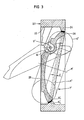
- the non-return valve shown in Figure 3 is of the type which is described in greater detail in SE-B-383 401 for which reason basically only the construction of the sealing device is described here.
- the valve comprises a valve housing 22 which forms internally a through-duct 23 and has a seat 24 extending round this, with its plane intersecting the through-duct.
- the valve member 25 which is formed to a dish-shaped valve flap is pivotally mounted by means of trunnion pins which are fitted in the housing and in the side edges of the valve flap and are located along the pivot axis V'.
- the valve member can move easily according to the flow of medium through the duct 23, so that it can pivot from an open position, shown in the Figure in thin lines, into its closed position by rotating counterclockwise as shown by the arrow 14.
- a first sealing surface which is convex and shaped as mentioned above as an obliquely cut toroid segment S' l .
- the surface can be produced, for instance, in an N.C. machine by turning it with the axis of rotation R' of the toroid T' as the centre, the point of the cutting tool being moved along the generatrix G' of the toroid.
- another sealing surface is produced which is concave and is designated S' 2 .
- first sealing surface S' which means that, after turning and possibly grinding, the pair of sealing surfaces which is to be incorporated in a specific valve can be lapped by machine, with the axis of the toroid again being used as the centre of rotation for the moving part which can be either the valve flap which is to be incorporated in the finished valve, or a so-called master.
- the sealing function is not restricted to a specific localised engagement line, but engagement can occur over an undefined part of the sealing surface width.
- a specific zone located, for example, in the centre plane A' of the sealing surfaces
- valve member Since, as is known with non-return valves, it is desired to arrange the valve member so that it is both statically and dynamically unbalanced, on order thereby to achieve rapid closing and low flow resistance when the valve is open, the choice of location for the pivot axis V' in this case is such that considerable lateral eccentricity is obtained, i.e. a position corresponding to the right-hand end of the area 21 in Figure 1.
- Similar positioning of the pivot axis is also to be recommended for a regulating valve, but in this case the aim should be a flap construction wherein the total force effect of the medium, that is, both the static and the dynamic moment, seeks to rotate the valve flap in one and the same direction, so that hysteresis in the regulating function is prevented over the whole operating range.
- the sealing device of the shut-off valve comprises a first sealing surface S" which is located on the periphery of the valve flap 27 and consists of a toroid segment shaped in accordance with one of the alternatives discussed above with reference to Figure 1, but preferably based on a convex curved line G".
- a radial recess 29 formed by a machined cut-out made in the housing wall and a clamping ring 31 fixed therein by means of screws 30, the inner part of this clamping ring forming an encircling shoulder.
- a seat ring 32 is fitted in the recess 29, having an external diameter which is less than the diameter of the base of the recess so that, in a known way the seat ring can be displaced to some extent in the radial direction, while its internal diameter should be so adapted to the sealing surface S" that the interior 33 of the ring which forms the other sealing surface, will engage against the periphery of the valve flap over a specific average sealing line L" when the valve is in its closed position.
- the seat ring 32 which is an oval tube in section, or which may be C-shaped, is given a cross-section profile on the interior 33 such that the curvature is appreciably greater than the curvature of the curved line of the toroid segment, which should also be the case when the curved line is concave.
- the wedge- like engagement between the two sealing surfaces therefore occurs substantially by linear contact.
- the seat ring 32 may flex somewhat by virtue of the inwards-facing part of the ring cross-section being deformed in the radial direction, which in turn means that the surface pressure is distributed in a peripheral direction.
- the planar shape of the ring is thereby altered to the same shape as that of the sealing surface S" in the plane of the engagement line L".
- a shut-off or regulating valve can have a reversed sealing surface configuration to that shown in Figure 4, so that the valve seat is constructed with a concave sealing surface with a toroidal shape, while the valve flap bears around its periphery a sealing ring with a round cross-section, made of an elastic material.
- valve comprising a sealing device according to the invention affords considerable advantages, due to its typical sealing surface shaping, both in the production process and with respect to functioning.
Landscapes
- Engineering & Computer Science (AREA)
- General Engineering & Computer Science (AREA)
- Mechanical Engineering (AREA)
- Lift Valve (AREA)
- Check Valves (AREA)
- Glass Compositions (AREA)
- Taps Or Cocks (AREA)
Priority Applications (1)
| Application Number | Priority Date | Filing Date | Title |
|---|---|---|---|
| AT82901315T ATE12049T1 (de) | 1981-04-27 | 1982-04-23 | Dichtungsanordnung fuer ventile. |
Applications Claiming Priority (2)
| Application Number | Priority Date | Filing Date | Title |
|---|---|---|---|
| SE8102638 | 1981-04-27 | ||
| SE8102638A SE427959B (sv) | 1981-04-27 | 1981-04-27 | Tetningsanordning for ventiler |
Publications (2)
| Publication Number | Publication Date |
|---|---|
| EP0089341A1 EP0089341A1 (en) | 1983-09-28 |
| EP0089341B1 true EP0089341B1 (en) | 1985-03-06 |
Family
ID=20343683
Family Applications (1)
| Application Number | Title | Priority Date | Filing Date |
|---|---|---|---|
| EP82901315A Expired EP0089341B1 (en) | 1981-04-27 | 1982-04-23 | A sealing device for valves |
Country Status (8)
| Country | Link |
|---|---|
| EP (1) | EP0089341B1 (enExample) |
| JP (1) | JPS58500578A (enExample) |
| CA (1) | CA1171052A (enExample) |
| DE (1) | DE3262486D1 (enExample) |
| FI (1) | FI73055C (enExample) |
| NO (1) | NO152986C (enExample) |
| SE (1) | SE427959B (enExample) |
| WO (1) | WO1982003899A1 (enExample) |
Families Citing this family (2)
| Publication number | Priority date | Publication date | Assignee | Title |
|---|---|---|---|---|
| EP3567287B1 (de) * | 2018-05-07 | 2021-03-03 | Gregor Gaida | Fünffach asymmetrisch aufgebaute absperrklappe |
| EP3581833B1 (de) * | 2018-06-11 | 2021-05-19 | Gregor Gaida | Sechsfach asymmetrisch aufgebaute absperrklappe |
Citations (1)
| Publication number | Priority date | Publication date | Assignee | Title |
|---|---|---|---|---|
| DE1198630B (de) * | 1960-10-26 | 1965-08-12 | Hans Eberhard Schmidt Dipl Ing | Absperr-, Rueckschlagklappe |
Family Cites Families (4)
| Publication number | Priority date | Publication date | Assignee | Title |
|---|---|---|---|---|
| US3172424A (en) * | 1962-07-24 | 1965-03-09 | Crawford K Stillwagon | Disc type check valve |
| AT324061B (de) * | 1972-04-27 | 1975-08-11 | Ecpp & Reuter Gmbh | Absperrklappe |
| SE383402B (sv) * | 1973-10-15 | 1976-03-08 | Saab Scania Ab | Vridspjellventil |
| SE399954B (sv) * | 1975-04-11 | 1978-03-06 | Saab Scania Ab | Spjellbackventil |
-
1981
- 1981-04-27 SE SE8102638A patent/SE427959B/sv not_active IP Right Cessation
-
1982
- 1982-04-23 EP EP82901315A patent/EP0089341B1/en not_active Expired
- 1982-04-23 WO PCT/SE1982/000130 patent/WO1982003899A1/en not_active Ceased
- 1982-04-23 DE DE8282901315T patent/DE3262486D1/de not_active Expired
- 1982-04-23 JP JP57501385A patent/JPS58500578A/ja active Granted
- 1982-04-26 CA CA000401626A patent/CA1171052A/en not_active Expired
- 1982-12-16 NO NO824245A patent/NO152986C/no unknown
-
1983
- 1983-05-02 FI FI831485A patent/FI73055C/fi not_active IP Right Cessation
Patent Citations (1)
| Publication number | Priority date | Publication date | Assignee | Title |
|---|---|---|---|---|
| DE1198630B (de) * | 1960-10-26 | 1965-08-12 | Hans Eberhard Schmidt Dipl Ing | Absperr-, Rueckschlagklappe |
Also Published As
| Publication number | Publication date |
|---|---|
| JPH0226106B2 (enExample) | 1990-06-07 |
| WO1982003899A1 (en) | 1982-11-11 |
| SE427959B (sv) | 1983-05-24 |
| SE8102638L (sv) | 1982-10-28 |
| FI73055C (fi) | 1987-08-10 |
| FI831485A0 (fi) | 1983-05-02 |
| NO824245L (no) | 1982-12-16 |
| FI73055B (fi) | 1987-04-30 |
| NO152986B (no) | 1985-09-16 |
| DE3262486D1 (en) | 1985-04-11 |
| EP0089341A1 (en) | 1983-09-28 |
| NO152986C (no) | 1985-12-27 |
| FI831485L (fi) | 1983-05-02 |
| CA1171052A (en) | 1984-07-17 |
| JPS58500578A (ja) | 1983-04-14 |
Similar Documents
| Publication | Publication Date | Title |
|---|---|---|
| US4480815A (en) | Sealing device for valves | |
| AU761816B2 (en) | Device for controlling flowing media | |
| JP2694956B2 (ja) | ちょう弁 | |
| US3765647A (en) | Valve construction and method | |
| US3379408A (en) | Eccentric plug valve | |
| US3963213A (en) | Butterfly valve | |
| US3883113A (en) | Fluid control ball valve structure for throttling service | |
| US3172424A (en) | Disc type check valve | |
| US5234193A (en) | Rotary plug valve with seat seal | |
| US2882010A (en) | Flow control valve | |
| US5682921A (en) | Undulating transverse interface for curved flapper seal | |
| EP0838003B1 (en) | Torsionally loaded fluid seals for rotary valves | |
| US3442488A (en) | Valve | |
| US3118465A (en) | Disc valve | |
| US3598363A (en) | Ball valve | |
| JPH0147671B2 (enExample) | ||
| GB2046882A (en) | Butterfly valve | |
| US5211373A (en) | Gate valve having expanding gate and floating seats | |
| JPH01188771A (ja) | 弁 | |
| US3473784A (en) | Resilient liner element for butterfly valves | |
| EP0089341B1 (en) | A sealing device for valves | |
| EP0216200A2 (en) | Cutoff valve, particularly for the cutoff of high-temperature fluids | |
| KR102067132B1 (ko) | 4중 편심 구조의 버터플라이 밸브 | |
| US4248404A (en) | Dual seal butterfly valve | |
| GB2092714A (en) | Seal rings for use in disc valves |
Legal Events
| Date | Code | Title | Description |
|---|---|---|---|
| PUAI | Public reference made under article 153(3) epc to a published international application that has entered the european phase |
Free format text: ORIGINAL CODE: 0009012 |
|
| 17P | Request for examination filed |
Effective date: 19830428 |
|
| AK | Designated contracting states |
Designated state(s): AT DE FR GB NL |
|
| GRAA | (expected) grant |
Free format text: ORIGINAL CODE: 0009210 |
|
| AK | Designated contracting states |
Designated state(s): AT DE FR GB NL |
|
| REF | Corresponds to: |
Ref document number: 12049 Country of ref document: AT Date of ref document: 19850315 Kind code of ref document: T |
|
| REF | Corresponds to: |
Ref document number: 3262486 Country of ref document: DE Date of ref document: 19850411 |
|
| ET | Fr: translation filed | ||
| RAP2 | Party data changed (patent owner data changed or rights of a patent transferred) |
Owner name: NAF AKTIEBOLAG |
|
| PLBE | No opposition filed within time limit |
Free format text: ORIGINAL CODE: 0009261 |
|
| STAA | Information on the status of an ep patent application or granted ep patent |
Free format text: STATUS: NO OPPOSITION FILED WITHIN TIME LIMIT |
|
| 26N | No opposition filed | ||
| NLT2 | Nl: modifications (of names), taken from the european patent patent bulletin |
Owner name: NAF AKTIEBOLAG TE LINKOEPING, ZWEDEN. |
|
| REG | Reference to a national code |
Ref country code: FR Ref legal event code: ST |
|
| PGFP | Annual fee paid to national office [announced via postgrant information from national office to epo] |
Ref country code: FR Payment date: 19990409 Year of fee payment: 18 |
|
| PGFP | Annual fee paid to national office [announced via postgrant information from national office to epo] |
Ref country code: AT Payment date: 19990415 Year of fee payment: 18 |
|
| PGFP | Annual fee paid to national office [announced via postgrant information from national office to epo] |
Ref country code: GB Payment date: 19990421 Year of fee payment: 18 |
|
| PGFP | Annual fee paid to national office [announced via postgrant information from national office to epo] |
Ref country code: DE Payment date: 19990430 Year of fee payment: 18 |
|
| PG25 | Lapsed in a contracting state [announced via postgrant information from national office to epo] |
Ref country code: GB Free format text: LAPSE BECAUSE OF NON-PAYMENT OF DUE FEES Effective date: 20000423 Ref country code: AT Free format text: LAPSE BECAUSE OF NON-PAYMENT OF DUE FEES Effective date: 20000423 |
|
| PGFP | Annual fee paid to national office [announced via postgrant information from national office to epo] |
Ref country code: NL Payment date: 20001026 Year of fee payment: 19 |
|
| GBPC | Gb: european patent ceased through non-payment of renewal fee |
Effective date: 20000423 |
|
| PG25 | Lapsed in a contracting state [announced via postgrant information from national office to epo] |
Ref country code: FR Free format text: LAPSE BECAUSE OF NON-PAYMENT OF DUE FEES Effective date: 20001229 |
|
| PG25 | Lapsed in a contracting state [announced via postgrant information from national office to epo] |
Ref country code: DE Free format text: LAPSE BECAUSE OF NON-PAYMENT OF DUE FEES Effective date: 20010201 |
|
| REG | Reference to a national code |
Ref country code: FR Ref legal event code: ST |
|
| PG25 | Lapsed in a contracting state [announced via postgrant information from national office to epo] |
Ref country code: NL Free format text: LAPSE BECAUSE OF NON-PAYMENT OF DUE FEES Effective date: 20011101 |
|
| NLV4 | Nl: lapsed or anulled due to non-payment of the annual fee |
Effective date: 20011101 |