EP0087366B1 - Kettenförderer für Wurzel- und Knollensammler - Google Patents
Kettenförderer für Wurzel- und Knollensammler Download PDFInfo
- Publication number
- EP0087366B1 EP0087366B1 EP83400347A EP83400347A EP0087366B1 EP 0087366 B1 EP0087366 B1 EP 0087366B1 EP 83400347 A EP83400347 A EP 83400347A EP 83400347 A EP83400347 A EP 83400347A EP 0087366 B1 EP0087366 B1 EP 0087366B1
- Authority
- EP
- European Patent Office
- Prior art keywords
- bar
- trap
- chain
- forming
- elevating
- Prior art date
- Legal status (The legal status is an assumption and is not a legal conclusion. Google has not performed a legal analysis and makes no representation as to the accuracy of the status listed.)
- Expired
Links
- 230000003028 elevating effect Effects 0.000 title claims abstract 30
- 230000001174 ascending effect Effects 0.000 claims abstract description 8
- 238000011144 upstream manufacturing Methods 0.000 claims description 6
- 239000002699 waste material Substances 0.000 description 6
- 238000004140 cleaning Methods 0.000 description 3
- 230000000694 effects Effects 0.000 description 3
- 235000016068 Berberis vulgaris Nutrition 0.000 description 2
- 241000335053 Beta vulgaris Species 0.000 description 2
- 239000002689 soil Substances 0.000 description 2
- 230000000903 blocking effect Effects 0.000 description 1
- 210000000078 claw Anatomy 0.000 description 1
- 238000010276 construction Methods 0.000 description 1
- 239000000203 mixture Substances 0.000 description 1
- 230000000717 retained effect Effects 0.000 description 1
- 238000005096 rolling process Methods 0.000 description 1
- 238000004804 winding Methods 0.000 description 1
Images

Classifications
-
- A—HUMAN NECESSITIES
- A01—AGRICULTURE; FORESTRY; ANIMAL HUSBANDRY; HUNTING; TRAPPING; FISHING
- A01D—HARVESTING; MOWING
- A01D17/00—Digging machines with sieving and conveying mechanisms
- A01D17/10—Digging machines with sieving and conveying mechanisms with smooth conveyor belts, lath bands or rake bands
- A01D2017/103—Constructional details of conveyor belts
Definitions
- the present invention relates to an improvement to the lifting chains of root or tuber loaders.
- it relates more particularly to an improvement to the lifting chains constituted by parallel bars mounted on two lateral chains driven by driving wheels and guide and return rollers, lifting chains which are positioned behind a cleaning and grouping turbine.
- this improvement can be applied to any conveyor chain on which a significant amount of soil can accumulate.
- the earth entrained with the tubers or other roots or adhering to them is, at the level of the turbine, projected outwards under the effect of the centrifugal force which is exerted due to the rotation of the turbine and a non-negligible part of the earth falls on the part of the lifting chain positioned below the rear part of the turbine.
- the oscillating elements which hang freely under the lower strand of the chain are thrown forward by centrifugal force at the level of the lower idler rollers and, in the case of a loader positioned behind a grouping turbine, the oscillating elements risk being spread by centrifugal force in the change of direction located under the turbine to intersect with the teeth of said turbine with the result of blocking the system.
- the oscillating elements are also liable, under the effect of centrifugal force, to reposition themselves upside down on the ascending strand without covering the excess spacing.
- the object of the present invention is to remedy these drawbacks by providing the lifting chain with a device which makes it possible to eliminate the earth rod at the critical point, namely in the lower part of the lower strand between the two idler rollers. lower.
- the subject of the present invention is an endless lifting conveyor chain with bars comprising, along its length, at least one gap between two successive bars and a device forming a hatch articulated along the bar, said bar thus delimiting one side of the gap and being located downstream.
- said over-spacing considering the direction of advance of said lifting chain, said hatch device being capable of obstructing at least partially the over-spacing along the ascending strands of the lifting chain ensuring transport, characterized in that the hatch device is secured with another bar of the lifting chain, said bar being adjacent and downstream of said articulation bar considering the direction of advancement of the lifting chain, said hatch device being maintained in a plane constituted by said bar of the lifting chain and its own articulation bar so as to obstruct by tially the excess spacing during the travel of the lifting chain along the ascending and descending strands of the straight travel of the lifting chain and to release it during changes of direction of the lifting chain in a vertical plane.
- the hatch device is constituted by two lateral flanges mounted for rotation at one of their ends on said articulation bar, flanges between which are fixed at least one bar or a plate so as to at least partially obstruct the overlap, said element extending on the side opposite to the flanges by an element for securing with the bar located downstream of the articulation bar.
- the joining element is constituted by a fork with two teeth fixed on the hatch device and extending on the side opposite to said device with respect to the articulation bar so that the respective teeth pass from on either side of the bar located downstream of the articulation bar.
- the securing element is constituted by a flange fixed by one of its ends to the device forming a hatch and extending on the opposite side of said device relative to the articulation bar, said flange being provided at its other end a tubular element of oval section in which is inserted the bar located downstream of the articulation bar.
- the hatch device is held in the plane defined by the bar on which it is rotatably mounted and by the chain element, in particular the neighboring bar.
- the lifting chain can be wound progressively without problem at the level of the drive wheels and the idler rollers.
- the present invention comprises, in combination with the hatch device, a protruding element on the inner surface of the lifting chain which is fixed to the bar of the lifting chain adjacent to the overhang and located upstream, considering the direction of advancement of the lifting chain, of the hatch device so as to prevent the waste from rolling, before the hatch opens, beyond the surface of the overhang so that it falls to through the clearance obtained by the tangential spacing of the hatch device at the level of the lower return rollers.
- the projecting element is produced by a pallet fixed by at least one fixing lug on the two bars of the lifting chain adjacent to the overhang and located upstream, considering the direction of advance of the chain. lifting, of the hatch device so as to protrude towards the inside of the lifting chain. It is obvious to a person skilled in the art that the pallet can advantageously be replaced by claws or similar devices.
- Figure 1 is a top view of the combination of a hatch device and a projecting member attached to a lifting chain according to the present invention
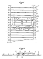
- Figures 2 and 3 are schematic side elevational views of the lower part of the lifting chain of a loader fitted with the devices of Figure 1, said devices being in two different positions near the lower idler rollers
- Figure 4 is a side elevational view of another embodiment of a hatch device.
- the reference 1 designates the lifting chain which is constituted in known manner by bars 2 fixed by riveting between two endless bands 3 which are driven by drive wheels and lower guide and return rollers.
- the lifting chain is provided over its length with overhangs 5. The overhangs are obtained by removing two parallel bars 2, which gives as explained below a sufficiently wide opening, cleared for a time long enough to allow the ejection of the earth rod.
- a hatch device 6 is mounted on the lifting chain 1, along one side of the over-spacing.
- This hatch device comprises a hatch element proper 7 constituted by two bars 8 mounted perpendicularly between three flanges 9, said bars 8 being positioned between the flanges 9 so as to replace the bars of the missing lifting chain when the hatch device is found in the chain path along the straight strands.
- One end of each flange 9 is fixed to a tubular element 10 in which is inserted the bar 2a of the lifting chain located just next to the overhang while the other end of the flange is free.
- said element 7 is extended on the side opposite the flanges 9 by two securing elements 11 which are each formed by a fork with two teeth 12, 13 including the handle 14 which extends one of the teeth 12 is fixed to one of the lateral flanges 9 and the teeth 12, 13 of which pass on each side of the bar 2b adjacent to the bar 2a on which the element 7 is articulated.
- FIG. 4 represents another embodiment of the securing element 11.
- the element forming the hatch proper is identical to the element 7 described above.
- the joining element is constituted by two flanges 15 which extend, on the side opposite to the hatch element 7, the two lateral flanges. Said flange is provided at its free end with a tubular element of oval section 16 into which is inserted the bar 2b of the lifting chain adjacent to the bar 2a of articulation of the element 7.
- This element 17 consists of a pallet 18 fixed by two tabs of attachment to the two bars 2c, 2d of the lifting chain adjacent to the overhang and opposite to the bar 2a.
- Each fixing lug is constituted by an L-shaped plate 20 on which a substantially S-shaped plate 21 comes to bear so as to form between the two plates a tubular part for the passage of the bar 2d.
- the pallet 18 is fixed by means of bolts 22 between the two projecting ends of the two plates 20, 21.
- FIGS 2 and 3 show the lower part of a lifting chain 1 positioned below the radial teeth 25 of a grouping turbine.
- the lifting chain 1 which comprises at least one over-spacing 5 is provided, in line with said over-spacing, with a device 6 forming a hatch 7 and with a projecting element 18.
- the turbine of grouping and cleaning projects on the lifting chain, at the same time as the beets to be loaded 23, clods of earth 24.
- the hatch element 7 is always maintained in the plane defined by the articulation bar 2a and the 'neighboring bar 2b on which the fixing element 11 is fixed. done as shown in FIG. 2, the hatch element 7 obstructs the over-spacing during the straight paths, but, as shown in FIG.
- the hatch element 7 deviates from the path of the lifting chain and releases the overhang so as to project outward through the cleared overhang, the rod of earth which is driven between the rollers 4.
- the projecting pallet 18 forms a stop for the above waste and keeps it above the hatch element so as to facilitate their ejection.
- the protruding pallet does not only serve as a stop for the clods of earth but also serves to clean the sleepers in the part of the lifting chain which provides transport.
Landscapes
- Life Sciences & Earth Sciences (AREA)
- Environmental Sciences (AREA)
- Harvesting Machines For Root Crops (AREA)
- Types And Forms Of Lifts (AREA)
Claims (6)
Priority Applications (1)
| Application Number | Priority Date | Filing Date | Title |
|---|---|---|---|
| AT83400347T ATE19913T1 (de) | 1982-02-23 | 1983-02-18 | Kettenfoerderer fuer wurzel- und knollensammler. |
Applications Claiming Priority (2)
| Application Number | Priority Date | Filing Date | Title |
|---|---|---|---|
| FR8202934A FR2521821B1 (fr) | 1982-02-23 | 1982-02-23 | Perfectionnement aux chaines elevatrices des chargeuses de racines ou tubercules |
| FR8202934 | 1982-02-23 |
Publications (2)
| Publication Number | Publication Date |
|---|---|
| EP0087366A1 EP0087366A1 (de) | 1983-08-31 |
| EP0087366B1 true EP0087366B1 (de) | 1986-05-28 |
Family
ID=9271247
Family Applications (1)
| Application Number | Title | Priority Date | Filing Date |
|---|---|---|---|
| EP83400347A Expired EP0087366B1 (de) | 1982-02-23 | 1983-02-18 | Kettenförderer für Wurzel- und Knollensammler |
Country Status (4)
| Country | Link |
|---|---|
| EP (1) | EP0087366B1 (de) |
| AT (1) | ATE19913T1 (de) |
| DE (1) | DE3363656D1 (de) |
| FR (1) | FR2521821B1 (de) |
Families Citing this family (1)
| Publication number | Priority date | Publication date | Assignee | Title |
|---|---|---|---|---|
| GB2226484A (en) * | 1988-12-30 | 1990-07-04 | Key Agricultural Limited | Crop-sorting apparatus; stone-separating |
Family Cites Families (5)
| Publication number | Priority date | Publication date | Assignee | Title |
|---|---|---|---|---|
| US2296810A (en) * | 1941-05-10 | 1942-09-22 | Eben D Dahlman | Elevator unit for conveyers |
| FR1105169A (fr) * | 1953-08-31 | 1955-11-28 | Nouveau convoyeur à chaîne muni de barreaux alternativement droits et déportés | |
| FR1117452A (fr) * | 1953-11-28 | 1956-05-23 | Machine à arracher et à trier les pommes de terre ou autres tubercules | |
| US3096875A (en) * | 1960-07-06 | 1963-07-09 | Dahlman Mfg & Sales Inc | Trap structure for link belt |
| FR2395694A1 (fr) * | 1977-06-29 | 1979-01-26 | Herriau Sa | Perfectionnement aux chaines-tabliers sans fin des ramasseuses de betteraves et racines analogues |
-
1982
- 1982-02-23 FR FR8202934A patent/FR2521821B1/fr not_active Expired
-
1983
- 1983-02-18 AT AT83400347T patent/ATE19913T1/de not_active IP Right Cessation
- 1983-02-18 EP EP83400347A patent/EP0087366B1/de not_active Expired
- 1983-02-18 DE DE8383400347T patent/DE3363656D1/de not_active Expired
Also Published As
| Publication number | Publication date |
|---|---|
| ATE19913T1 (de) | 1986-06-15 |
| EP0087366A1 (de) | 1983-08-31 |
| FR2521821B1 (fr) | 1985-06-07 |
| DE3363656D1 (en) | 1986-07-03 |
| FR2521821A1 (fr) | 1983-08-26 |
Similar Documents
| Publication | Publication Date | Title |
|---|---|---|
| EP0014298B1 (de) | Umlaufende Fördereinrichtung mit örtlich unterschiedlichen Geschwindigkeiten und Anwendung für Rollsteige | |
| FR2474272A1 (fr) | Systeme d'alimentation pour l'ensemble de traitement d'une moissonneuse-batteuse | |
| EP1194031B1 (de) | Vorrichtung und verfahren zur bodenbelüftung mit abfallsammlung | |
| FR2988707A1 (fr) | Poubelle enterree a barriere mobile. | |
| EP0087366B1 (de) | Kettenförderer für Wurzel- und Knollensammler | |
| FR2503577A1 (fr) | Filtre a tablier filtrant mobile | |
| FR2614013A1 (fr) | Dispositif pour le transport de pots de filature comportant un organe de transport circulant | |
| FR2825390A1 (fr) | Dispositif de nettoyage de plage | |
| FR2658380A1 (fr) | Sabot de guidage des graines, adaptable sur un soc de semoir. | |
| FR2575397A1 (fr) | Filtre a tablier filtrant mobile ferme en boucle sur lui-meme | |
| FR2691873A1 (fr) | Presse de mise en balles. | |
| EP0456592B1 (de) | Fangvorrichtung für einen Rasenmäher, mit einem abnehmbaren Boden, die erlaubt, das Schnittgut direkt fallen zu lassen | |
| FR2675007A1 (fr) | Dispositif de collecte et de convoyage de baies et fruits dans une machine de recolte. | |
| FR2598059A1 (fr) | Distributeur centrifuge notamment de paille ou de fourrage | |
| FR2815056A1 (fr) | Poste de recuperation de dechets destine a un dispositif de nettoyage de plage | |
| EP1234618A1 (de) | Vorrichtung und Verfahren zum Entfernen von mit von dem Boden geernteten Früchten vermischten Fremdkörpern | |
| EP0100292A1 (de) | Heuwerbungsmaschine | |
| FR2495585A1 (fr) | Convoyeur a poussoirs ou racleurs | |
| FR2657335A1 (fr) | Convoyeur pour machine a vendanger. | |
| EP0059671B1 (de) | Einrichtung zum Sammeln und Reinigen der Ernte, insbesondere Rüben | |
| FR2750443A1 (fr) | Systeme de raclage d'une aire | |
| FR2529749A1 (en) | Maize harvester gathering head | |
| FR2590760A1 (fr) | Perfectionnements aux dispositifs convoyeurs de machine a vendanger | |
| FR2474282A1 (fr) | Machine a ebouter les haricots verts | |
| FR2566226A1 (fr) | Dispositif d'epandage a herissons verticaux pour epandeurs de fumier, lisier ou autres. |
Legal Events
| Date | Code | Title | Description |
|---|---|---|---|
| PUAI | Public reference made under article 153(3) epc to a published international application that has entered the european phase |
Free format text: ORIGINAL CODE: 0009012 |
|
| AK | Designated contracting states |
Designated state(s): AT BE CH DE GB IT LI LU NL SE |
|
| 17P | Request for examination filed |
Effective date: 19840222 |
|
| GRAA | (expected) grant |
Free format text: ORIGINAL CODE: 0009210 |
|
| AK | Designated contracting states |
Kind code of ref document: B1 Designated state(s): AT BE CH DE GB IT LI LU NL SE |
|
| PG25 | Lapsed in a contracting state [announced via postgrant information from national office to epo] |
Ref country code: NL Effective date: 19860528 Ref country code: IT Free format text: LAPSE BECAUSE OF FAILURE TO SUBMIT A TRANSLATION OF THE DESCRIPTION OR TO PAY THE FEE WITHIN THE PRESCRIBED TIME-LIMIT;WARNING: LAPSES OF ITALIAN PATENTS WITH EFFECTIVE DATE BEFORE 2007 MAY HAVE OCCURRED AT ANY TIME BEFORE 2007. THE CORRECT EFFECTIVE DATE MAY BE DIFFERENT FROM THE ONE RECORDED. Effective date: 19860528 Ref country code: AT Effective date: 19860528 |
|
| REF | Corresponds to: |
Ref document number: 19913 Country of ref document: AT Date of ref document: 19860615 Kind code of ref document: T |
|
| PG25 | Lapsed in a contracting state [announced via postgrant information from national office to epo] |
Ref country code: SE Effective date: 19860531 |
|
| REF | Corresponds to: |
Ref document number: 3363656 Country of ref document: DE Date of ref document: 19860703 |
|
| NLV1 | Nl: lapsed or annulled due to failure to fulfill the requirements of art. 29p and 29m of the patents act | ||
| PG25 | Lapsed in a contracting state [announced via postgrant information from national office to epo] |
Ref country code: LU Free format text: LAPSE BECAUSE OF NON-PAYMENT OF DUE FEES Effective date: 19870228 Ref country code: LI Effective date: 19870228 Ref country code: CH Effective date: 19870228 |
|
| PLBE | No opposition filed within time limit |
Free format text: ORIGINAL CODE: 0009261 |
|
| STAA | Information on the status of an ep patent application or granted ep patent |
Free format text: STATUS: NO OPPOSITION FILED WITHIN TIME LIMIT |
|
| 26N | No opposition filed | ||
| REG | Reference to a national code |
Ref country code: CH Ref legal event code: PL |
|
| PGFP | Annual fee paid to national office [announced via postgrant information from national office to epo] |
Ref country code: DE Payment date: 19890216 Year of fee payment: 7 |
|
| PGFP | Annual fee paid to national office [announced via postgrant information from national office to epo] |
Ref country code: GB Payment date: 19890228 Year of fee payment: 7 |
|
| PGFP | Annual fee paid to national office [announced via postgrant information from national office to epo] |
Ref country code: BE Payment date: 19890303 Year of fee payment: 7 |
|
| PG25 | Lapsed in a contracting state [announced via postgrant information from national office to epo] |
Ref country code: GB Effective date: 19900218 |
|
| PG25 | Lapsed in a contracting state [announced via postgrant information from national office to epo] |
Ref country code: BE Effective date: 19900228 |
|
| BERE | Be: lapsed |
Owner name: HERRIAU SOCIETE ANONYME Effective date: 19900228 |
|
| GBPC | Gb: european patent ceased through non-payment of renewal fee | ||
| PG25 | Lapsed in a contracting state [announced via postgrant information from national office to epo] |
Ref country code: DE Effective date: 19901101 |