EP0087315A2 - Überprüfen der Funktion von elektronischen Waagen - Google Patents
Überprüfen der Funktion von elektronischen Waagen Download PDFInfo
- Publication number
- EP0087315A2 EP0087315A2 EP83300916A EP83300916A EP0087315A2 EP 0087315 A2 EP0087315 A2 EP 0087315A2 EP 83300916 A EP83300916 A EP 83300916A EP 83300916 A EP83300916 A EP 83300916A EP 0087315 A2 EP0087315 A2 EP 0087315A2
- Authority
- EP
- European Patent Office
- Prior art keywords
- mode
- state
- key
- input device
- checking
- Prior art date
- Legal status (The legal status is an assumption and is not a legal conclusion. Google has not performed a legal analysis and makes no representation as to the accuracy of the status listed.)
- Granted
Links
Images


Classifications
-
- G—PHYSICS
- G01—MEASURING; TESTING
- G01G—WEIGHING
- G01G23/00—Auxiliary devices for weighing apparatus
- G01G23/18—Indicating devices, e.g. for remote indication; Recording devices; Scales, e.g. graduated
- G01G23/36—Indicating the weight by electrical means, e.g. using photoelectric cells
- G01G23/37—Indicating the weight by electrical means, e.g. using photoelectric cells involving digital counting
-
- G—PHYSICS
- G01—MEASURING; TESTING
- G01G—WEIGHING
- G01G19/00—Weighing apparatus or methods adapted for special purposes not provided for in the preceding groups
- G01G19/40—Weighing apparatus or methods adapted for special purposes not provided for in the preceding groups with provisions for indicating, recording, or computing price or other quantities dependent on the weight
- G01G19/413—Weighing apparatus or methods adapted for special purposes not provided for in the preceding groups with provisions for indicating, recording, or computing price or other quantities dependent on the weight using electromechanical or electronic computing means
- G01G19/414—Weighing apparatus or methods adapted for special purposes not provided for in the preceding groups with provisions for indicating, recording, or computing price or other quantities dependent on the weight using electromechanical or electronic computing means using electronic computing means only
- G01G19/4144—Weighing apparatus or methods adapted for special purposes not provided for in the preceding groups with provisions for indicating, recording, or computing price or other quantities dependent on the weight using electromechanical or electronic computing means using electronic computing means only for controlling weight of goods in commercial establishments, e.g. supermarket, P.O.S. systems
Definitions
- This invention relates to a method of selecting the operating mode of an electronic scale of the type for measuring weights of articles and for computing and displaying the cost of the articles and the number thereof, based on the measured weight, which method allows the operation of the scale to be checked with facility.
- the invention further relates to an electronic scale which uses the aforementioned method.
- Scales which basically are for weighing articles have undergone remarkable technological advancements in recent years and now are capable not only of weighing but also of computing the cost of a batch of articles as well as the number of individual articles among articles of the same shape, provided that the scale is supplied with inputs of unit price and unit weight.
- Scales having the foregoing capabilities are referred to as electronic scales and have an input device such as a keyboard as well as arithmetic circuitry.
- the external appearance of such an electronic scale is as shown in Fig. 1, in which (A) is a perspective view of the overall scale, (B) is an enlarged view of a display provided on the electronic scale, and (C) is an enlarged view of an operation panel also provided on the electronic scale.
- the electronic scale includes a main body 100 incorporating various control circuits, a weighing tray 101 provided on the main body 100 for receiving the articles to be weighed, and a display device 5 supported on a column 102 affixed to the main body 100.
- the front side of the main body 100 is provided with an operation panel 103 having an input device 1 and a power switch 104.
- the display device 5, shown in greater detail in Fig. l(B), is composed of a weight display section 5a for displaying the measured weight of articles placed on the weighing tray 101, a unit price display section 5b for displaying a unit price entered by operating the input device 1, and a cost display section 5c for displaying a cost computed from the measured weight and set unit price.
- the input device 1 of the operation panel 103 includes a ten-key arrangement of numeric keys from “0” to “9", as well as function keys marked “ZERO”, “PRINT”, “TARE”, “UNIT PRICE” ".” and "CL”.
- the electronic scale comprises a weight sensor A for sensing the weight of articles placed in the weighing tray 101, an arithmetic device 2 including a weight computing unit B for computing true weight by subtracting the tare weight from the output of the weight sensor A, and a cost computing unit for computing cost by multiplying the true weight by a unit price, the display device 5 for displaying, e.g., unit price, tare weight and cost, and the input device 1 having the ten-key arrangement and function keys for providing the arithmetic device 2 and display device 5 with inputs of unit price and tare weight.
- the arithmetic device 2 is provided with a RAM (random access memory) for storing various data, and with a printer (not shown) having printing circuitry and a printing drum.
- the weight sensor A is equipped with an A-D converter (analog-to-digital) converter for converting a measured analog weight into a digital value.
- An electronic scale of the above type having a large number of components arranged in the manner described, is checked at the factory prior to delivery to make sure that all the components are operating normally. Similarly, if a complaint stemming from a malfunction or failure is received from a user, the components must also be checked to locate the source of the problem. In either case, items checked are as follows:
- the display device is checked to assure that the display segments for the numerals 0 through 9 light properly.
- the RAM in the microcomputer of the arithmetic device 2 is checked for malfunction.
- the characters (printing type) on the printing drum are checked for flaws.
- the printing circuitry is checked for defects.
- the display circuitry is checked for defects.
- checking an electronic scale for the aforesaid items entails provided the scale with a special start switch, externally connecting a read-only memory (ROM) to the arithmetic device of the electronic scale, which ROM contains a stored test program for checking purposes, and turning on the start switch so that the arithmetic device may execute the test program stored in the ROM.
- ROM read-only memory
- the check for item (1) may be executed by pressing the numeric key marked "1"
- the check for item (2) by pressing the numeric key marked "2”, and so on.
- the electronic scale must be specially provided with the start switch.
- Another disadvantage is that the ROM must be connected to the scale, making it difficult for an ordinary user to perform the check himself. The procedure can be troublesome even for a skilled dealer.
- An embodiment of the present invention can provide a method of selecting the operating mode of an electronic scale, and an electronic scale using said method, wherein an operational check mode can be designated by an input device without providing the input device with additional keys.
- Another embodiment of the present invention can provide a method of selecting the operating mode of an electronic scale, and an electronic scale using said method, wherein an operational check mode as well as a computing mode of the electronic scale can be designated selectively by an input device provided on the electronic scale.
- a method of selecting the operating mode of an electronic scale, and an electronic scale using said method wherein either a computing mode or checking mode is selected and operation is executed based on the selected mode.
- the computing mode is a mode wherein an arithmetic operation is performed based on the weight of articles sensed by a weight sensor and on items of data input from an input device having a plurality of keys, and wherein a display device displays information relating to the articles, which information includes the result of the arithmetic operation.
- the checking mode is a mode wherein the operation of the electronic scale is checked for abnormality.
- the method includes steps of sensing the state of each key of the input device at the time that power is introduced to the electronic scale, selecting the computing mode to enable execution of operation in said mode when it is sensed in the first step that no key of the input device is in the ON state, and selecting the checking mode to enable execution of operation in said mode when it is sensed in the first step that any key of the input device is in the ON state. It is thus possible to select either a computing mode or checking mode depending upon whether or not a key is pressed at the introduction of power to the electronic scale. This facilitates the checking operation and enables an ordinary user to check the operation of the electronic scale in a simple manner.
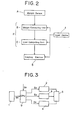
- the electronic scale incorporates the input device 1, the arithmetic device 2, a checking device 3, and the display device 5 for displaying information entered by the input device 1, the result of calculation performed by the arithmetic device 2, and the result of a checking operation performed by the checking device 3.
- the checking device 3 performs the check for item (1) when a "1" numeric key is pressed, the check for item (2) when a "2" numeric key is pressed, and so on for the items (3) through (8) when the numeric keys "3" through “8" are pressed, respectively.
- Designated at 4 is a short-circuit alarm device. Each numeric key and each of several function keys has a particular number assigned thereto. If any of these keys should develop a short circuit, the alarm device 4 will cause the corresponding number to be displayed on the display device 5.
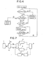
- the electronic scale is arranged to activate either the arithmetic device 2 to establish a computing mode or the checking device 3 to establish a checking mode, depending upon the particular situation. To this end, when power has been introduced, the electronic scale discriminates whether any key on the input device 1 is in the ON state (indicating closure of the associated switch contacts), and then selects the operating mode based on the result of the discrimination.
- the relevant processing expressed in simplified form in the flowchart of Fig. 4, proceeds as follows:
- the foregoing method of selecting the operating mode can be realized through use of a processor (CPU) 9 arranged as shown in Fig. 3, the processor having been programmed in the appropriate manner.
- the CPU 9 When required, the CPU 9 generates a command signal S2 for activating the arithmetic device 2, a command signal S3 for activating the checking device 3, and a command signal S4 for activating the alarm device 4.
- a signal S5, produced when power is introduced, is applied to the CPU 9.
- the input device 1 applies a key ON signal S6 to the CPU 9 when any key is in the ON state at the time that power is introduced.
- the signal S6 When the operator wishes to establish the checking mode and, hence, places any key in the ON (depressed) state intentionally as he introduces power and then releases the key thereafter, the signal S6 will, if conditions are normal, go high (logical "1") only for as long as the key is held depressed following the introduction of power. However, if any key on the input device 1 has developed a short circuit, then signal S6 will go high at the instant power is applied and will remain high even after the passage of a fixed period of time.
- the CPU 9 decides to produce the arithmetic device activation command S2 or the checking device activation command S3 depending upon whether the key ON signal (logical "1") is an input thereto at the introduction of power. If a short circuit is discriminated, then the CPU 9 issues the alarm device activation command S4 to set the alarm device 4 into operation.
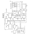
- the input device 1 includes key contacts 10a through lOn and a decoder circuit 11.
- the display device 5 includes display elements 50a through 50n, each display element being composed of a numeric display member constituted by seven segments.
- the display device 5 also includes a segment driver 51 for driving the segments of each of the display elements 50a through 50n, as well as a digit driver for driving the digits composed of the display elements 50a through 50n.
- the abovementioned arithmetic device 2, checking device 3, alarm device 4 and CPU 9 are constituted by a control circuit constructed of blocks 90 through 94, interconnected by a bus line 95.
- Block 90 represents a processor such as a microprocessor.
- Block 91 is a read-only memory (ROM) for storing the control program of the processor 90.
- the control program contains a mode selection program, a computation program for when the electronic scale performs an actual weighing operation, and a test program for executing a checking operation.
- Block 92 is a random access memory (RAM) for storing the result of computations performed by the processor 90, for storing data received from the input device 1, and for storing weight values obtained from a weight sensor, described in further detail below.
- the blocks 93, 94 are input/output ports, the former connected to the display device 5, the latter connected to a printer 110, described below.
- the bus line 95 mentioned earlier is an address/data bus.
- the aforementioned printer 110 has a print driver 111 and printing mechanism 112 and is adapted to print out, on receipts, labels and the like, such information as the weight, unit price and cost of the articles weighed.
- a weight sensor 121 senses the weight of articles placed in the abovementioned weighing tray and may comprise a load cell.
- the output of the weight sensor 121 is applied to an analog-to-digital (A-D) converter 122 for converting the weight sensor output, namely an analog value indicative of the sensed weight, into a digital value.
- A-D analog-to-digital
- the processor executes a key check program. According to this program, the number (code) assigned to a key will be displayed by the processor on the display device 5 when the corresponding key is pressed. This allows the operator to visually confirm proper operation of the keys and of the decoder 11.
- a display segment check program is executed wherein the processor 90 causes each of the display elements 50a through 50n of the display device 5 to be activated repeatedly for all of the numerals from “0" to "9". This makes it possible to confirm visually whether the segments of the display elements 50a through 50n are operating normally.
- Pressing the "4" key causes the processor 90 to execute a RAM check program, wherein the processor writes data into the RAM 92, reads the data out of the RAM and then compares the written and read data to check the operation of the RAM, will the result being displayed on display device 5.
- Pressing the "5" key initiates execution of a printing drum check program, wherein the processor 90 causes the printer 110 to print out the same numeral in all columns, i.e., in digit place. This is repeated for all numerals from “0" to "9" so that the printing type on the printing drum of the printing mechanism 12 may be checked for flaws.
- the processor executes a print driver check program, wherein the processor causes the printer 110 to print out a different numeral in each column. Whether the print driver is operating normally or not can be judged based on the results of the print out.
- the operator initiates execution of a display brightness check program, wherein the processor 90 activates all segments of all digits made up of the display elements 50a through 50n. This enables the operator to check the brightness of each digit.
- the test program is composed of zero-adjust, key check, display segment check, RAM check, printing drum check, print driver check, display driver check and display brightness check programs, the executed check program being decided by whichever of the "1" through “8" keys of the input device 1 is pressed by the operator.
- the check program is ended by pressing the "CLEAR” key (Fig. lc) of the input device 1.
- the processor 90 Upon sensing that the "CLEAR" key has been pressed, the processor 90 returns to step (e) to initiate the , checking mode. As long as the checking mode is not cancelled by pressing the "0" key, therefore, the operator can have the required checking operation executed merely by pressing the corresponding key. To cancel the checking mode, the operator need only press the "0" key, the processor 9.0 responding by establishing the computing mode.
- the power ON signal S5 and key ON signal S6 are connected to a switching device 6.
- the switching device 6 applies the activation command signal S2 to the arithmetic device through a locking circuit 7.
- the switching device applies the activation command signal S3 to the checking device 3 through the locking circuit 7.
- the latter circuit is adapted to prevent activation of the checking device 3 when the arithmetic device 2 has been activated, and vice versa.
- the signal S3 is also connected to a timing device 8, which is set into operation when the signal S3 goes high, indicating the key ON state (i.e., that the key ON signal S6 is high). If the signal S6 and, hence, signal S3, are still high even after the passage of the preset time, then the timing device 8 will issue the command signal S4 to activate the alarm device 4.
- the switching device 6 comprises switching logic for converting the key ON signal S6 into a control signal.
- the switching device 6 includes a gate 61 which receives the power ON signal S5 as one input thereto, as well as the signal S6 applied through a NOT gate 63, and a gate 62 whose inputs are the signal S5 as well as the signal S6, the latter being received directly from the input device 1.
- the locking circuit 7 comprises an RS flip-flop 71, an AND gate 72 one input whereof is the reset output of the RS flip-flop 71, the input whereof is the output of gate 61 in switching device 6, and an AND gate 73 one input whereof is the set output of the RS flip-flop 71, the other input whereof is the output of NOT gate 63 in switching device 6.
- the output of AND gate 72 is connected to the input side of the arithmetic device 2, and the output of AND gate 73 is connected to the input side of the checking device 3.
- the output of gate 62 in the switching device 6 is connected to the set input terminal of the RS flip-flop 71.
- the timing device 8 which is the stage preceding the alarm device 4, comprises a timer 81 and an AND gate 82 whose two inputs are the key ON signal S6 from the switching device 6, and the output of timer 71.
- the output of gate 61 of the switching device 6 will go high, forming the arithmetic device activation command signal S2, when power is introduced in the absence of a key ON signal from the input device 1.
- Flip-flop 71 will remain in the reset state. Under these conditions, the signal S2 is delivered by the AND gate 72, activating solely the arithmetic device 2.
- gate 62 will deliver the key ON signal S6 and flip-flop 71 will be held in the set state. If a key OFF state is subsequently established, sending the output of NOT gate 63 high, then the output of AND gate 73 also will go high, forming the checking device activation command signal S3 that is applied to the checking device 3 so that only the latter is activated.
- the alarm device 4 will be set into operation by the activation command signal 4, which will be produced by the timer 81 when the set time expires.
- the alarm device 4 can be adapted to actuate a bell or the like to inform the operator of the short circuit by means of an audible alarm, or to present a visual warning using the display device 5.
- the foregoing discussion relates to the signal path for designating activation of the computing device 2, checking device 3 and alarm device 4.
- the actual arrangement of the signal path is similar to that shown in Fig. 5.
- signal transmission for the ordinary operating mode namely the transmission of signals from the input device 1, arithmetic device 2 and display device 5, takes place via a data bus D.
Landscapes
- Physics & Mathematics (AREA)
- Engineering & Computer Science (AREA)
- Mathematical Physics (AREA)
- Theoretical Computer Science (AREA)
- General Physics & Mathematics (AREA)
- Cash Registers Or Receiving Machines (AREA)
- Accessory Devices And Overall Control Thereof (AREA)
- Input From Keyboards Or The Like (AREA)
Applications Claiming Priority (2)
| Application Number | Priority Date | Filing Date | Title |
|---|---|---|---|
| JP57026957A JPS58143221A (ja) | 1982-02-22 | 1982-02-22 | 電子秤の作動モ−ド選択方法及びその方法を用いた電子秤 |
| JP26957/82 | 1982-02-22 |
Publications (3)
| Publication Number | Publication Date |
|---|---|
| EP0087315A2 true EP0087315A2 (de) | 1983-08-31 |
| EP0087315A3 EP0087315A3 (en) | 1985-06-05 |
| EP0087315B1 EP0087315B1 (de) | 1988-06-29 |
Family
ID=12207633
Family Applications (1)
| Application Number | Title | Priority Date | Filing Date |
|---|---|---|---|
| EP83300916A Expired EP0087315B1 (de) | 1982-02-22 | 1983-02-22 | Überprüfen der Funktion von elektronischen Waagen |
Country Status (4)
| Country | Link |
|---|---|
| US (1) | US4509608A (de) |
| EP (1) | EP0087315B1 (de) |
| JP (1) | JPS58143221A (de) |
| DE (1) | DE3377229D1 (de) |
Cited By (2)
| Publication number | Priority date | Publication date | Assignee | Title |
|---|---|---|---|---|
| CN105527006A (zh) * | 2015-12-23 | 2016-04-27 | 民勤县邦德贸易有限公司 | 一种台面可调具有抗电磁干扰功能的多点式电子台秤 |
| CN105628163A (zh) * | 2015-12-23 | 2016-06-01 | 民勤县邦德贸易有限公司 | 一种具有抗电磁干扰仪表盘可转动的多点式电子台秤 |
Families Citing this family (10)
| Publication number | Priority date | Publication date | Assignee | Title |
|---|---|---|---|---|
| DE3407463A1 (de) * | 1984-02-29 | 1985-08-29 | August Sauter Gmbh, 7470 Albstadt | Messgeraet, insbesondere waage, mit selbsttaetiger betriebsartumschaltung (modeumschaltung) |
| US4660663A (en) * | 1986-05-27 | 1987-04-28 | Ncr Corporation | Method of calibrating a weighing apparatus within an enclosure |
| US4760539A (en) * | 1986-05-27 | 1988-07-26 | Ncr Corporation | Method of calibrating a weighing apparatus |
| US4751661A (en) * | 1986-05-27 | 1988-06-14 | Ncr Corporation | Automatic zero balancing of a weighing apparatus |
| DE3631487A1 (de) * | 1986-09-16 | 1988-03-17 | Mettler Instrumente Ag | Geraet, insbesondere waage, mit einer anzeige der resultate von nacheinander erfolgenden ausgewaehlten funktionsablaeufen |
| US4849918A (en) * | 1987-12-30 | 1989-07-18 | Pitney Bowes Inc. | Weighing instrument having adaptive breakpoints |
| US4864521A (en) * | 1987-12-30 | 1989-09-05 | Pitney Bowes Inc. | Multiranging scale with blanking of rate display |
| US4909338A (en) * | 1989-06-12 | 1990-03-20 | Ncr Corporation | Method and apparatus for scale calibration and weighing |
| SG52955A1 (en) * | 1996-04-18 | 1998-09-28 | Texas Instruments Inc | Detector and method for detecting defects in the magnetic media of a mass storage system |
| US6974075B1 (en) * | 2003-10-17 | 2005-12-13 | Duke Peter S | Method of controlling a person's weight |
Family Cites Families (7)
| Publication number | Priority date | Publication date | Assignee | Title |
|---|---|---|---|---|
| US3521039A (en) * | 1968-02-26 | 1970-07-21 | Reliance Electric & Eng Co | Computer verification |
| US3556235A (en) * | 1969-09-15 | 1971-01-19 | Hobart Mfg Co | Photocell checking circuit for optical weighing scale |
| US3899951A (en) * | 1973-08-09 | 1975-08-19 | Nippon Musical Instruments Mfg | Key switch scanning and encoding system |
| US3936807A (en) * | 1974-04-12 | 1976-02-03 | Michigan Avenue National Bank Of Chicago | Sensor based computer terminal |
| US4055753A (en) * | 1975-12-15 | 1977-10-25 | Hobart Corporation | Computing weighing scale |
| SE446226B (sv) * | 1980-02-26 | 1986-08-18 | Teraoka Seikosho Kk | Anordning for att meta vikt, berekna pris och utfora forpackning |
| CH649839A5 (de) * | 1981-02-06 | 1985-06-14 | Mettler Instrumente Ag | Verfahren zum waehlen eines von mehreren moeglichen betriebsparametern einer elektrischen waage. |
-
1982
- 1982-02-22 JP JP57026957A patent/JPS58143221A/ja active Granted
-
1983
- 1983-02-22 US US06/468,706 patent/US4509608A/en not_active Expired - Lifetime
- 1983-02-22 DE DE8383300916T patent/DE3377229D1/de not_active Expired
- 1983-02-22 EP EP83300916A patent/EP0087315B1/de not_active Expired
Cited By (2)
| Publication number | Priority date | Publication date | Assignee | Title |
|---|---|---|---|---|
| CN105527006A (zh) * | 2015-12-23 | 2016-04-27 | 民勤县邦德贸易有限公司 | 一种台面可调具有抗电磁干扰功能的多点式电子台秤 |
| CN105628163A (zh) * | 2015-12-23 | 2016-06-01 | 民勤县邦德贸易有限公司 | 一种具有抗电磁干扰仪表盘可转动的多点式电子台秤 |
Also Published As
| Publication number | Publication date |
|---|---|
| DE3377229D1 (en) | 1988-08-04 |
| EP0087315A3 (en) | 1985-06-05 |
| JPH0216854B2 (de) | 1990-04-18 |
| EP0087315B1 (de) | 1988-06-29 |
| JPS58143221A (ja) | 1983-08-25 |
| US4509608A (en) | 1985-04-09 |
Similar Documents
| Publication | Publication Date | Title |
|---|---|---|
| US4660160A (en) | Electronic weighing device having label printer with data stability check | |
| US4509608A (en) | Method of selecting electronic scale operating mode, and electronic scale using said method | |
| JPH0514210B2 (de) | ||
| US4392535A (en) | Zero-point adjusting method for automatic weighing apparatus | |
| JPH0365594B2 (de) | ||
| US4412591A (en) | Method and apparatus for selecting operating modes or parameters in an electrical scale | |
| US4114706A (en) | Electrical weighing apparatus | |
| US4325441A (en) | Error alarm system in a combined electronic weighing scale and electronic cash register | |
| US4836309A (en) | Electronic weighing instrument | |
| US4638435A (en) | Electronic cash register having direct price look-up function | |
| US4428049A (en) | Training mode operation in an electronic cash register | |
| JPH0348455B2 (de) | ||
| JPS6342210B2 (de) | ||
| JP2617250B2 (ja) | 電子式金銭登録機 | |
| KR0129012B1 (ko) | 자동판매기의 매상집계 제어방법 | |
| JP2546662B2 (ja) | 電子秤 | |
| JPS6120019B2 (de) | ||
| GB1584639A (en) | Data processing apparatus for use with weighing balances | |
| JPS5847476Y2 (ja) | 電子式キヤツシユレジスタ | |
| JPS6366743B2 (de) | ||
| JP2502354B2 (ja) | 電子キャッシュレジスタ | |
| JPS6212844B2 (de) | ||
| JPS5853293B2 (ja) | 電子式デジタル表示秤の風袋量設定装置 | |
| JPS6126891Y2 (de) | ||
| JPS5853643Y2 (ja) | 電子式キャッシュレジスタ |
Legal Events
| Date | Code | Title | Description |
|---|---|---|---|
| PUAI | Public reference made under article 153(3) epc to a published international application that has entered the european phase |
Free format text: ORIGINAL CODE: 0009012 |
|
| AK | Designated contracting states |
Designated state(s): DE GB NL SE |
|
| PUAL | Search report despatched |
Free format text: ORIGINAL CODE: 0009013 |
|
| AK | Designated contracting states |
Designated state(s): DE GB NL SE |
|
| 17P | Request for examination filed |
Effective date: 19851029 |
|
| 17Q | First examination report despatched |
Effective date: 19861015 |
|
| GRAA | (expected) grant |
Free format text: ORIGINAL CODE: 0009210 |
|
| AK | Designated contracting states |
Kind code of ref document: B1 Designated state(s): DE GB NL SE |
|
| REF | Corresponds to: |
Ref document number: 3377229 Country of ref document: DE Date of ref document: 19880804 |
|
| PLBE | No opposition filed within time limit |
Free format text: ORIGINAL CODE: 0009261 |
|
| STAA | Information on the status of an ep patent application or granted ep patent |
Free format text: STATUS: NO OPPOSITION FILED WITHIN TIME LIMIT |
|
| 26N | No opposition filed | ||
| REG | Reference to a national code |
Ref country code: FR Ref legal event code: ST |
|
| EAL | Se: european patent in force in sweden |
Ref document number: 83300916.0 |
|
| PGFP | Annual fee paid to national office [announced via postgrant information from national office to epo] |
Ref country code: GB Payment date: 19980213 Year of fee payment: 16 |
|
| PGFP | Annual fee paid to national office [announced via postgrant information from national office to epo] |
Ref country code: SE Payment date: 19980218 Year of fee payment: 16 |
|
| PGFP | Annual fee paid to national office [announced via postgrant information from national office to epo] |
Ref country code: NL Payment date: 19980226 Year of fee payment: 16 |
|
| PGFP | Annual fee paid to national office [announced via postgrant information from national office to epo] |
Ref country code: DE Payment date: 19980302 Year of fee payment: 16 |
|
| PG25 | Lapsed in a contracting state [announced via postgrant information from national office to epo] |
Ref country code: GB Free format text: LAPSE BECAUSE OF NON-PAYMENT OF DUE FEES Effective date: 19990222 |
|
| PG25 | Lapsed in a contracting state [announced via postgrant information from national office to epo] |
Ref country code: SE Free format text: LAPSE BECAUSE OF NON-PAYMENT OF DUE FEES Effective date: 19990223 |
|
| PG25 | Lapsed in a contracting state [announced via postgrant information from national office to epo] |
Ref country code: NL Free format text: LAPSE BECAUSE OF NON-PAYMENT OF DUE FEES Effective date: 19990901 |
|
| GBPC | Gb: european patent ceased through non-payment of renewal fee |
Effective date: 19990222 |
|
| EUG | Se: european patent has lapsed |
Ref document number: 83300916.0 |
|
| PG25 | Lapsed in a contracting state [announced via postgrant information from national office to epo] |
Ref country code: DE Free format text: LAPSE BECAUSE OF NON-PAYMENT OF DUE FEES Effective date: 19991201 |