EP0086379B1 - Werkzeugwechsler - Google Patents
Werkzeugwechsler Download PDFInfo
- Publication number
- EP0086379B1 EP0086379B1 EP83100808A EP83100808A EP0086379B1 EP 0086379 B1 EP0086379 B1 EP 0086379B1 EP 83100808 A EP83100808 A EP 83100808A EP 83100808 A EP83100808 A EP 83100808A EP 0086379 B1 EP0086379 B1 EP 0086379B1
- Authority
- EP
- European Patent Office
- Prior art keywords
- tool
- claws
- receiving member
- wedges
- sleeve
- Prior art date
- Legal status (The legal status is an assumption and is not a legal conclusion. Google has not performed a legal analysis and makes no representation as to the accuracy of the status listed.)
- Expired
Links
- 238000005553 drilling Methods 0.000 claims abstract description 21
- 210000000078 claw Anatomy 0.000 claims description 28
- 238000001816 cooling Methods 0.000 claims description 2
- 238000006073 displacement reaction Methods 0.000 claims description 2
- 230000001050 lubricating effect Effects 0.000 claims 1
- 239000010687 lubricating oil Substances 0.000 abstract 1
- 238000000034 method Methods 0.000 description 9
- 239000002826 coolant Substances 0.000 description 5
- 239000000314 lubricant Substances 0.000 description 5
- 239000005068 cooling lubricant Substances 0.000 description 4
- 238000010276 construction Methods 0.000 description 2
- 238000007789 sealing Methods 0.000 description 2
- 210000002023 somite Anatomy 0.000 description 2
- 241001295925 Gegenes Species 0.000 description 1
- 238000011161 development Methods 0.000 description 1
- 230000018109 developmental process Effects 0.000 description 1
- 238000003754 machining Methods 0.000 description 1
- 238000012986 modification Methods 0.000 description 1
- 230000004048 modification Effects 0.000 description 1
- 230000035515 penetration Effects 0.000 description 1
Images


Classifications
-
- B—PERFORMING OPERATIONS; TRANSPORTING
- B23—MACHINE TOOLS; METAL-WORKING NOT OTHERWISE PROVIDED FOR
- B23B—TURNING; BORING
- B23B31/00—Chucks; Expansion mandrels; Adaptations thereof for remote control
- B23B31/02—Chucks
- B23B31/24—Chucks characterised by features relating primarily to remote control of the gripping means
- B23B31/26—Chucks characterised by features relating primarily to remote control of the gripping means using mechanical transmission through the working-spindle
- B23B31/261—Chucks characterised by features relating primarily to remote control of the gripping means using mechanical transmission through the working-spindle clamping the end of the toolholder shank
-
- B—PERFORMING OPERATIONS; TRANSPORTING
- B23—MACHINE TOOLS; METAL-WORKING NOT OTHERWISE PROVIDED FOR
- B23Q—DETAILS, COMPONENTS, OR ACCESSORIES FOR MACHINE TOOLS, e.g. ARRANGEMENTS FOR COPYING OR CONTROLLING; MACHINE TOOLS IN GENERAL CHARACTERISED BY THE CONSTRUCTION OF PARTICULAR DETAILS OR COMPONENTS; COMBINATIONS OR ASSOCIATIONS OF METAL-WORKING MACHINES, NOT DIRECTED TO A PARTICULAR RESULT
- B23Q3/00—Devices holding, supporting, or positioning work or tools, of a kind normally removable from the machine
- B23Q3/155—Arrangements for automatic insertion or removal of tools, e.g. combined with manual handling
- B23Q3/1552—Arrangements for automatic insertion or removal of tools, e.g. combined with manual handling parts of devices for automatically inserting or removing tools
- B23Q3/15553—Tensioning devices or tool holders, e.g. grippers
-
- Y—GENERAL TAGGING OF NEW TECHNOLOGICAL DEVELOPMENTS; GENERAL TAGGING OF CROSS-SECTIONAL TECHNOLOGIES SPANNING OVER SEVERAL SECTIONS OF THE IPC; TECHNICAL SUBJECTS COVERED BY FORMER USPC CROSS-REFERENCE ART COLLECTIONS [XRACs] AND DIGESTS
- Y10—TECHNICAL SUBJECTS COVERED BY FORMER USPC
- Y10T—TECHNICAL SUBJECTS COVERED BY FORMER US CLASSIFICATION
- Y10T408/00—Cutting by use of rotating axially moving tool
- Y10T408/44—Cutting by use of rotating axially moving tool with means to apply transient, fluent medium to work or product
-
- Y—GENERAL TAGGING OF NEW TECHNOLOGICAL DEVELOPMENTS; GENERAL TAGGING OF CROSS-SECTIONAL TECHNOLOGIES SPANNING OVER SEVERAL SECTIONS OF THE IPC; TECHNICAL SUBJECTS COVERED BY FORMER USPC CROSS-REFERENCE ART COLLECTIONS [XRACs] AND DIGESTS
- Y10—TECHNICAL SUBJECTS COVERED BY FORMER USPC
- Y10T—TECHNICAL SUBJECTS COVERED BY FORMER US CLASSIFICATION
- Y10T408/00—Cutting by use of rotating axially moving tool
- Y10T408/44—Cutting by use of rotating axially moving tool with means to apply transient, fluent medium to work or product
- Y10T408/45—Cutting by use of rotating axially moving tool with means to apply transient, fluent medium to work or product including Tool with duct
- Y10T408/455—Conducting channel extending to end of Tool
-
- Y—GENERAL TAGGING OF NEW TECHNOLOGICAL DEVELOPMENTS; GENERAL TAGGING OF CROSS-SECTIONAL TECHNOLOGIES SPANNING OVER SEVERAL SECTIONS OF THE IPC; TECHNICAL SUBJECTS COVERED BY FORMER USPC CROSS-REFERENCE ART COLLECTIONS [XRACs] AND DIGESTS
- Y10—TECHNICAL SUBJECTS COVERED BY FORMER USPC
- Y10T—TECHNICAL SUBJECTS COVERED BY FORMER US CLASSIFICATION
- Y10T409/00—Gear cutting, milling, or planing
- Y10T409/30—Milling
- Y10T409/303976—Milling with means to control temperature or lubricate
- Y10T409/304032—Cutter or work
-
- Y—GENERAL TAGGING OF NEW TECHNOLOGICAL DEVELOPMENTS; GENERAL TAGGING OF CROSS-SECTIONAL TECHNOLOGIES SPANNING OVER SEVERAL SECTIONS OF THE IPC; TECHNICAL SUBJECTS COVERED BY FORMER USPC CROSS-REFERENCE ART COLLECTIONS [XRACs] AND DIGESTS
- Y10—TECHNICAL SUBJECTS COVERED BY FORMER USPC
- Y10T—TECHNICAL SUBJECTS COVERED BY FORMER US CLASSIFICATION
- Y10T409/00—Gear cutting, milling, or planing
- Y10T409/30—Milling
- Y10T409/309352—Cutter spindle or spindle support
Definitions
- the invention relates to a tool changer for a deep drilling machine with a rotary driven tool spindle and a receiving part which has a conical inner surface into which the conical shaft of a tool holder intended for receiving a deep drilling tool with an inner channel can be inserted, and in which clamping devices are provided in the receiving part, which are provided on Engage the shaft of the tool holder and act on it in the axial direction under the pressure of a spring, and in which the tool holder and a pipe arranged inside the tool spindle and rotating with it for the supply and discharge of coolant and / or lubricant have internal channels, that are related to each other.
- Such a tool changer is known from DE-OS 29 21 961.
- the clamping devices are formed by balls arranged in a clamping cage, which press against a collar on the shaft of the tool holder; the tensioning cage is integrally formed with a tensioning rod, which is pulled into the tensioning position by a package of disc springs.
- the plate springs are supported on a support arm connected to the tool spindle.
- the connection of the inner channels in the tool holder and in the pipe for the supply and discharge of coolant and / or lubricant is carried out by telescopic line connections.
- a disadvantage of such a construction of the tool changer is that the clamping devices - formed by the balls - do not all exert uniform force on the tool holder as a result of the smallest machining inaccuracies of the balls, the clamping cage which guides them and the collar on the tool holder which they act on .
- this type of clamping uses a common clamping element (in DE-OS 2921 961 ; Tension rod 22; in DE-OS 16 02 890: Bund 88) only some of the tensioning devices always absorb the entire tension force, while others are not involved in the tensioning process.
- telescopic line connections not described in DE-OS 29 21 961 are constructed in a relatively complicated manner and do not allow simple and reliable sealing with automatic tool change.
- the difficulty generally lies in reliably and simply connecting the inner channels to one another in a sealing manner, while the tool holder, which holds the deep drilling tool firmly, has to be accommodated in a corresponding receiving part on the tool spindle.
- the object of the invention is accordingly to provide a tool changer of the type mentioned which, with a simple structural design, ensures a rapid change of the deep drilling tool with a safe connection of the inner channels for the supply or discharge of the coolant and / or lubricant.
- a quick change should be possible by simply manipulating a part (gripper) of an automatic machine tool.
- the clamping devices are designed as claws which can be pivoted in the receiving part and engage in a groove on the shank of the tool holder, which have inclined surfaces and are pressed into the clamping position by wedges which are axially displaceable in the receiving part and which also have inclined surfaces, whereby If the inclined surfaces come into contact with one another, self-locking interlocks, and that each wedge is individually assigned a spring supported in the receiving part, and that the tube, which is rotating in the tool spindle, is pressed against the tool holder by a further spring, and that a device for releasing is also provided the self-locking of the wedges is provided by moving them in the axial direction against the force of the spring mentioned.
- the invention further relates to several advantageous developments.
- the structure of the tool changer according to the invention is considerably simpler than in the prior art mentioned at the beginning.
- the push rod mentioned there (reference number 15) can be omitted and, accordingly, the receiving part can also be made simpler and more stable.
- the clamping devices are formed by claws which are held in the clamping position by self-locking by means of individual spring-loaded wedges. This results in an even distribution of the clamping force across all claws. With this tension of the tool, the tool holder can also be pressed against the coolant and / or lubricant-carrying pipe in a particularly simple manner on the end face. To ensure a secure concern, part of the invention is that this tube is under spring pressure.
- this tube has no function to perform when clamping the tool holder, while in the state of the art mentioned it has both a tension rod and a cooling and / or lubricant line.
- the telescopic line connections used in the prior art can be omitted.
- the deep drilling tool 1 has an inner channel 2.
- the inner channel 2 is used in the so-called Single-lip drilling method for supplying the coolant lubricant to the cutting edge of the tool, which sits on the left end (not shown) of the deep drilling tool 1 in the figure.
- the cooling lubricant is supplied outside, on the circumference of the tool, and is discharged together with the chips via the inner channel 2.
- the embodiment shown in the drawing has the object of a deep drilling tool according to this BTA method; Via the inner channel 2, which continues through the entire spindle, cooling lubricant is discharged together with the chips from left to right and then finally emerges from the spindle, as indicated by the arrow on the right in the figure.
- the deep drilling tool sits firmly in a sleeve 3. This is e.g. achieved in that the sleeve 3 is soldered or screwed onto the deep drilling tool 1.
- the left area of the sleeve 3 is provided with an external thread 4.
- a stop nut 5 sits on this external thread 4. Its position defines the position of the tool holder 6 relative to the sleeve 3.
- the tool holder 6 is connected to the sleeve 3 in that a wedge 8 is inserted into the groove 7 in the tool holder 6 as well as in one Groove 7 'engages in the sleeve 3. This connection is provided several times along the circumference.
- An external thread is also provided on the left sleeve-like end 9 of the tool holder 6, on which a union nut 10 is arranged. If it is tightened, the tool holder 6 is fixed in the position relative to the sleeve 3 which is determined by the position of the stop nut 5 on the external thread 4.
- the inner channel 2 continues into the inner channel 11 in the sleeve 3, the (inner channel) 12 in the tool holder 6 and the inner channel 58 in the tube 52.
- the tube 52 is arranged resiliently in the tool spindle 22.
- Deep drilling tool 1 and tool holder 6 form a unit 13 which, as such, should be automatically replaceable on the tool spindle (drilling spindle) as part of a machine tool.
- Automatic interchangeability means that a gripper (not shown) grips the unit (e.g. by engaging in the groove 14 on the tool holder 6) and simply inserting or removing it in the tool changer.
- the conical shaft 15 of the tool holder 6 is used for this purpose.
- the torque is transmitted by driving stones 59.
- the tool holder 6 is inserted into the conical inner surface 16 of the receiving part 17 (receiving cone), which is part of the tool adapter 18.
- the tool adapter 18 has the receiving part 17 and a flange 19, which are connected by means of screws 20.
- the flange 19 is coupled in the direction of rotation by driving stones 21 to the tool spindle 22, which is driven in a known manner (not shown).
- the driving stones engage in corresponding grooves in the adapter cylinder 19 and in the tool spindle 22.
- the receiving part 17 is provided with several slots along its circumference. Of these, the slots 17 'and 17 "can be seen.
- claws 24 are pivotally mounted by means of bolts. In the position shown (clamping position), the claws engage in a groove 25 which is connected to the hub-like extension 26 which extends to the right Tool receptacle 6. In the clamping position, the rear flanks 27 of the claws 24 do not run parallel to the axis of the tool changer, but rather obliquely at a certain angle to them Wedges 28 rest on the oblique flank 27 of the claws 24.
- the claws 24 and the wedges 28 are so coordinated with one another such that they are self-locking in the clamping position and can only be relaxed with an externally applied force.
- the engagement of the claws 24 in the groove 25 holds the tool holder 6 on the tool spindle 22, since the claws 24 on the receiving part 17, the receiving part 17 on the flange 19, and the flange 19 is held on the tool spindle 22.
- Studs 30 are inserted in the wedges 28.
- Springs 31 are placed over them and are supported in recesses 32 in the receiving part 17. These springs press the wedges 28 into the clamping position shown.
- a sliding sleeve 33 is also arranged within the flange 19. Part of this sliding sleeve 33 is an expeller sleeve 34.
- the left end 50 of the expeller sleeve 34 extends into the space between the claws 24 up to the incision 51 on the conical shaft 15 of the tool holder 6.
- the sliding sleeve 33 has stop surfaces 35 with which the sliding sleeve 33 presses against the right end of the wedges 28.
- the sliding sleeve 33 is connected to a sliding sleeve 38 by means of sleeves 36 and screws 37.
- the sleeves 36 and the screws 37 extend through a slot 39 in the flange 19. In this way, the sliding sleeve 33 is connected in terms of movement to the sliding sleeve 38 in the event of a displacement in the axial direction.
- the sliding sleeve 38 To shift the sliding sleeve 38, it has a circumferential groove 40. Claws 41 engage in this groove on both sides (cf. FIG. 2). These claws are arranged on a shift fork 42, which is fastened by means of a bolt 43 to a bracket 44, which in turn is firmly connected to the spindle housing 45. The shift fork 42 is moved with the aid of a hydraulic cylinder 46, the piston rod 47 of which acts on the upper end of the shift fork 42 at 48.
- the tool holder 6 In this unlocked position, the tool holder 6 can thus be moved out of engagement with the holder part 17 of the tool adapter by a gripper, etc. Another tool can be used.
- the tensioning takes place in that the hydraulic shift cylinder 46 moves the piston rod 47 to the left. Accordingly, the sliding sleeve 38 moves to the right. Then the wedge pieces 28 are also pressed to the right by the springs 31. Thus, the oblique surfaces 29 of the wedge pieces 28 then press against the rear flanks 27 of the claws 24 and thus hold them radially inward in the position in which there is self-locking and the tool adapter is clamped.
- the cooling lubricant in the BTA process (or the same in the single-lip drilling process) is removed, as already mentioned, via the inner channel 2 of the deep drilling tool 1 and then via the inner channel 12 of the tool holder 6.
- the inner channel 12 of the tool holder 6 closes flush with the inner channel 58 of the spring-loaded tube 52.
- a collar 54 is attached to this tube with the aid of two Seeger rings 53. Between the collar 54 and a stop 55 in the tool spindle 22, a spring 56 is attached, which presses the collar 54 and thus the tube 52 to the left, so that the left end edge of the tube presses against the right end edge of the tool holder 6 and there a seal forms.
- the movement of the tube and thus of the collar 54 to the left is limited by a pin 57 which is arranged in the tool spindle 22.
- a stud 30 ' is screwed into each wedge piece 28'.
- the stud bolts 30 ' pass through the sliding sleeve 33' and drag the wedge pieces 28 'with them via a spring 31', so that each claw 24 'rests in the groove 25 via spring force and thus clamps the tool holder 6 in the receiving part 7.
- the same parts are identified in FIG. 3 with the same reference numerals as in FIG. 1.
- the exemplary embodiments are also described with regard to the so-called BTA method and the single-lip drilling method, in which, as mentioned, the cooling lubricant is fed to the outside of the circumference of the tool or inside the tool and through to the inner channel 2 of the tool below Take away the chips.
- the invention is also applicable to the so-called ejector drilling method, which is based on a double pipe construction.
- the tool holder 6 can not only be provided with a conical, as described, but also with a cylindrical holder.
Landscapes
- Engineering & Computer Science (AREA)
- Mechanical Engineering (AREA)
- Drilling And Boring (AREA)
- Vehicle Body Suspensions (AREA)
- Forklifts And Lifting Vehicles (AREA)
- Mechanically-Actuated Valves (AREA)
- Automatic Tool Replacement In Machine Tools (AREA)
- Auxiliary Devices For Machine Tools (AREA)
- Gripping On Spindles (AREA)
Description
- Die Erfindung betrifft einen Werkzeugwechsler für eine Tiefbohrmaschine mit einer drehangetriebenen Werkzeugspindel und einem Aufnahmeteil, das eine konische Innenfläche aufweist, in die der konische Schaft einer zur Aufnahme eines Tiefbohrwerkzeugs mit Innenkanal bestimmten Werkzeugaufnahme einsteckbar ist, und bei der im Aufnahmeteil Spanneinrichtungen vorgesehen sind, die am Schaft der Werkzeugaufnahme eingreifen und unter dem Druck einer Feder auf diese in axialer Richtung einwirken, und bei dem die Werkzeugaufnahme sowie ein innerhalb der Werkzeugspindel angeordnetes und sich mit dieser mitdrehendes zur Zu- und Ableitung von Kühl- und/oder Schmiermittel dienendes Rohr Innenkanäle aufweisen, die miteinander in Verbindung stehen.
- Ein derartiger Werkzeugwechsler ist aus der DE-OS 29 21 961 bekannt. Die Spanneinrichtungen werden durch in einem Spannkäfig angeordnete Kugeln gebildet, die gegen einen Bund am Schaft der Werkzeugaufnahme drücken; dabei ist der Spannkäfig mit einer Spannstange integral ausgebildet, die durch ein Paket Tellerfedern in Spannstellung gezogen wird. Dabei stützen sich die Tellerfedern an einem mit der Werkzeugspindel verbundenen Stützarm ab. Die Verbindung der Innenkanäle in der Werkzeugaufnahme und in dem zur Zu- und Ableitung von Kühl- und/oder Schmiermittel dienenden Rohr erfolgt dabei durch teleskopartige Leitungsverbindungen.
- Nachteilig ist bei einem derartigen Aufbau des Werkzeugwechslers, dass die Spanneinrichtungen - gebildet durch die Kugeln - in Folge von kleinsten Bearbeitungsungenauigkeiten der Kugeln, des sie führenden Spannkäfigs und des Bundes an der Werkzeugaufnahme, auf den sie einwirken, nicht alle gleichmässig Kraft auf die Werkzeugaufnahme ausüben. Es zeigt sich in der Praxis bei dieser oder ähnlicher Ausbildung des Werkzeugwechslers, auch wenn man statt der Kugeln andere Spanneinrichtungen, etwa Klauen gemäss der DE-OS 1602890 verwendet, dass bei dieser Art Spannung über ein gemeinsames Spannelement (bei der DE-OS 2921 961; Spannstange 22; bei der DE-OS 16 02 890: Bund 88) stets nur einige der Spanneinrichtungen die gesamte Spannkraft aufnehmen, während andere an dem Spannvorgang nicht beteiligt sind.
- Ausserdem sind die in der DE-OS 29 21 961 nicht näher erläuterten telekopartigen Leitungsverbindungen relativ kompliziert aufgebaut und ermöglichen keine einfache und sichere Abdichtung bei automatischem Werkzeugwechsel.
- Beim automatischen Werkzeugwechsel besteht generell die Schwierigkeit darin, die Innenkanäle zuverlässig schnell und einfach miteinander abdichtend zu verbinden, während die das Tiefbohrwerkzeug fest aufnehmende Werkzeugaufnahme in einen entsprechenden Aufnahmeteil an der Werkzeugspindel aufgenommen werden muss.
- Aufgabe der Erfindung ist es demgemäss, einen Werkzeugwechsler der eingangs genannten Art zu schaffen, der bei einfachem konstruktiven Aufbau ein rasches Wechseln des Tiefbohrwerkzeuges bei sicherem Anschluss der Innenkanäle für die Zuleitung bzw. Ableitung des Kühl- und/oder Schmiermittels gewährleistet. Dabei soll insbesondere ein schneller Wechsel durch einfache Manipulation eines Teiles (Greifers) einer automatischen Werkzeugmaschine möglich sein.
- Diese Aufgabe wird erfindungsgemäss dadurch gelöst, dass die Spanneinrichtungen als im Aufnahmeteil verschwenkbare und in eine Nut am Schaft der Werkzeugaufnahme eingreifende Klauen ausgebildet sind, die Schrägflächen aufweisen und durch im Aufnahmeteil axial verschiebbare Keile, die ebenfalls Schrägflächen aufweisen, in Spannstellung gedrückt werden, wobei durch Anliegen der Schrägflächen aneinander eine Verriegelung durch Selbsthemmung eintritt, und dass jedem Keil einzeln eine im Aufnahmeteil abgestützte Feder zugeordnet ist, und dass ferner das in der Werkzeugspindel mitdrehend angeordnete Rohr durch eine weitere Feder gegen die Werkzeugaufnahme gedrückt wird, und dass ferner eine Einrichtung zum Lösen der Selbsthemmung der Keile durch Verschiebung derselben in axialer Richtung gegen die Kraft der genannten Feder vorgesehen ist. Die Erfindung betrifft ferner mehrere vorteilhafte Weiterbildungen.
- Der Aufbau des erfindungsgemässen Werkzeugwechslers ist erheblich einfacher als beim eingangs genannten Stand der Technik. So kann insbesondere die dort genannte Schubstange (Bezugszeichen 15) wegfallen und demgemäss auch der Aufnahmeteil einfacher und stabiler ausgebildet werden. Die Spanneinrichtungen werden durch Klauen gebildet, die durch einzelne federbelastete Keile durch Selbsthemmung in Spannstellung gehalten werden. Es ergibt sich damit eine gleichmässige Verteilung der Spannkraft auf sämtliche Klauen. Bei dieser Spannung des Werkzeuges kann in besonders einfacher Weise auch die Werkzeugaufnahme stirnseitig gegen das Kühl- und/oder Schmiermittel führende Rohr angedrückt werden. Um ein sicheres Anliegen zu gewährleisten, ist Bestandteil der Erfindung, dass dieses Rohr unter Federdruck steht. Dies wird ermöglicht, weil - in Abweichung von dem Stand der Technik etwa gemäss DE-OS 29 21 961 - dieses Rohr bei der Spannung der Werkzeugaufnahme keine Funktion zu erfüllen hat, während es bei dem genannten Stand der Technik sowohl Spannstange als auch Kühl-und/oder Schmiermittelleitung ist. Die beim Stand der Technik verwendeten teleskopartigen Leitungsverbindungen können wegfallen.
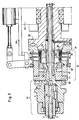
- Ausführungsbeispiele der Erfindung werden im folgenden anhand der beigefügten Zeichnungen beschrieben. Es stellen dar:
- Figur 1 ein erstes Ausführungsbeispiel;
- Figur 2 eine schematische Darstellung der Schaltgabel in einer Ebene senkrecht zur Ebene von Figur 1;
- Figur 3 ein zweites Ausführungsbeispiel.
- Das Tiefbohrwerkzeug 1 weist einen Innenkanal 2 auf. Der Innenkanal 2 dient bei dem sog. Einlippen-Bohrverfahren zur Zufuhr des Kühlmittelschmierstoffes an die Schneide des Werkzeuges, die an dem in der Figur linken (nicht gezeigten) Ende des Tiefbohrwerkzeugs 1 sitzt. Beim sog. BTA-Verfahren wird der Kühlschmierstoff aussen, am Umfang des Werkzeugs, zugeführt und zusammen mit den Spänen über den Innenkanal 2 abgeführt. Das in der Zeichnung dargestellte Ausführungsbeispiel hat ein Tiefbohrwerkzeug nach diesem BTA-Verfahren zum Gegenstand; über den Innenkanal 2, der sich durch die gesamte Spindel hindurch fortsetzt, wird Kühlschmierstoff zusammen mit den Spänen von links nach rechts abgeführt und tritt dann schliesslich, wie in der Figur rechts durch den Pfeil angedeutet, aus der Spindel aus.
- Das Tiefbohrwerkzeug sitzt fest in einer Hülse 3. Dies ist z.B. dadurch erreicht, dass die Hülse 3 auf das Tiefbohrwerkzeug 1 aufgelötet oder aufgeschraubt wird. Der linke Bereich der Hülse 3 ist mit einem Aussengewinde 4 versehen. Auf diesem Aussengewinde 4 sitzt eine Anschlagmutter 5. Ihre Stellung definiert die Lage der Werkzeugaufnahme 6 relativ zur Hülse 3. Die Werkzeugaufnahme 6 ist mit der Hülse 3 dadurch verbunden, dass ein Keil 8 sowohl in die Nut 7 in der Werkzeugaufnahme 6 als auch in eine Nut 7' in der Hülse 3 eingreift. Diese Verbindung ist mehrfach entlang des Umfangs vorgesehen. Am linken manschettenartigen Ende 9 der Werkzeugaufnahme 6 ist ebenfalls ein Aussengewinde vorgesehen, auf dem eine Überwurfmutter 10 angeordnet ist. Wird sie angezogen, so ist die Werkzeugaufnahme 6 in derjenigen Lage gegenüber der Hülse 3 fixiert, die durch die Lage der Anschlagmutter 5 auf dem Aussengewinde 4 bestimmt wird. Der Innenkanal 2 setzt sich fort in den Innenkanal 11 in der Hülse 3, den (nnenkana) 12 in der Werkzeugaufnahme 6 und den Innenkanal 58 im Rohr 52.Das Rohr 52 ist in der Werkzeugspindel 22 federnd angeordnet.
- Tiefbohrwerkzeug 1 und Werkzeugaufnahme 6 bilden eine Einheit 13, die als solche im Rahmen einer Werkzeugmaschine an der Werkzeugspindel (Bohrspindel) automatisch auswechselbar sein soll. Automatische Auswechselbarkeit bedeutet, dass ein Greifer (nicht gezeigt) die Einheit fasst (z.B. durch Eingreifen in die Nut 14 an der Werkzeugaufnahme 6) und sie in den Werkzeugwechsler einfach einsetzt bzw. herausnimmt. Hierzu dient der konische Schaft 15 der Werkzeugaufnahme 6. Die Drehmomentübertragung erfolgt durch Mitnahmesteine 59.
- Zur Aufnahme der Einheit 13 an der Werkzeugspindel 22 wird die Werkzeugaufnahme 6 in die konische Innenfläche 16 des Aufnahmeteils 17 (Aufnahmekonus) gesteckt, der Teil des Werkzeugadapters 18 ist.
- Der Werkzeugadapter 18 weist den Aufnahmeteil 17 und einen Flansch 19 auf, die mittels Schrauben 20 verbunden sind. Der Flansch 19 ist in Drehrichtung durch Mitnahmesteine 21 mit der Werkzeugspindel 22 gekoppelt, die in bekannter Weise angetrieben wird (nicht gezeigt). Die Mitnahmesteine greifen in entsprechende Nuten in den Adapterzylinder 19 und in der Werkzeugspindel 22 ein.
- Der Aufnahmeteii 17 ist entlang seines Umfanges mit mehreren Schlitzen versehen. Davon sind die Schlitze 17' und 17" ersichtlich. In diesen Schlitzen sind mittels Bolzen 23 Klauen 24 schwenkbar gelagert. In der gezeigten Stellung (Spannstellung) greifen die Klauen in eine Nut 25 ein, die an dem sich nach rechts erstreckenden nabenartigen Ansatz 26 der Werkzeugaufnahme 6 vorgesehen ist. In Spannstellung verlaufen die Rückflanken 27 der Klauen 24 nicht parallel zur Achse des Werkzeugwechslers, sondern schräg unter einem bestimmten Winkel dazu. An der Schrägflanke 27 der Klauen 24 liegen Keile 28 an. Die Klauen 24 und die Keile 28 sind so aufeinander abgestimmt, dass sie in Spannstellung selbsthemmend sind und nur mit einer von aussen eingeleiteten Kraft zu entspannen sind. Somit wird durch den Eingriff der Klauen 24 in die Nut 25 die Werkzeugaufnahme 6 an der Werkzeugspindel 22 gehalten, da die Klauen 24 am Aufnahmeteil 17, der Aufnahmeteil 17 am Flansch 19, und der Flansch 19 an der Werkzeugspindel 22 gehalten ist.
- In den Keilen 28 stecken Stehbolzen 30. Über sie sind Federn 31 gesteckt, die im Aufnahmeteil 17 in Ausnehmungen 32 abgestützt sind. Diese Federn drücken die Keile 28 in die dargestellte Spannstellung.
- Innerhalb des Flansches 19 ist ferner eine Schiebemuffe 33 angeordnet. Bestandteil dieser Schiebemuffe 33 ist eine Austreiberhülse 34. Das linke Ende 50 der Austreiberhülse 34 erstreckt sich in den Raum zwischen den Klauen 24 bis zum Einschnitt 51 am konischen Schaft 15 der Werkzeugaufnahme 6. Ferner weist die Schiebemuffe 33 Anschlagflächen 35 auf, mit denen die Schiebemuffe 33 gegen das rechte Ende der Keile 28 drückt. Mittels Hülsen 36 und Schrauben 37 ist die Schiebemuffe 33 mit einer Schiebehülse 38 verbunden. Die Hülsen 36 und die Schrauben 37 erstrecken sich durch einen Schlitz 39 im Flansch 19 hindurch. Auf diese Weise ist also die Schiebemuffe 33 bewegungsmässig bei einer Verschiebung in axialer Richtung mit der Schiebehülse 38 verbunden.
- Zur Verschiebung der Schiebehülse 38 weist diese eine umlaufende Nut 40 auf. In dieser Nut greifen zu beiden Seiten Klauen 41 ein (vgl. Figur 2). Diese Klauen sind an einer Schaltgabel 42 angeordnet, die mit Hilfe eines Bolzens 43 an einem Ausleger 44 befestigt ist, der seinerseits mit dem Spindelgehäuse 45 fest verbunden ist. Die Bewegung der Schaltgabel 42 erfolgt mit Hilfe eines hydraulischen Zylinders 46, dessen Kolbenstange 47 am oberen Ende der Schaltgabel 42 bei 48 angreift.
- Die Entriegelung der Einheit 13 geht nun folgendermassen vor sich:
- Der hydraulische Zylinder 46 wird so betätigt, dass sich die Kolbenstange 47 und mit ihr das obere Ende der Schaltgabel 42 nach rechts bewegt. Dann wird die Schiebehülse 38 nach links verschoben. Da sie über Hülsen 36 und Schrauben 37 mit der Schiebemuffe 33 verbunden ist, bewegt sich auch diese nach links.
- Das bedeutet, erstens, dass die Anschlagflächen 35 die Keile 28 nach links verschieben. Somit werden die Rückflanken 27 der Klauen 24 freigegeben. Die Klauen 24 können sich nun in radialer Richtung nach aussen schwenken. Zweitens bewegt sich mit der Schiebehülse 38 und der Schiebemuffe 33 auch die Austreiberhülse 34 nach links und trifft auf den Radius 49 der Klauen 24. Dies erzwingt die Schwenkbewegung der Klauen 24 nach aussen. Die Klauen 24 bewegen sich also aus der Nut 25 der Werkzeugaufnahme 6 heraus und geben sie damit frei. Diese Bewegung geht so lange weiter, bis das linke vordere Ende 50 der Austreiberhülse 34 mit ihrer Stirnfläche an dem Einschnitt 51, der einen Anschlag bildet, anschlägt. Durch dieses Anschlagen wird die Werkzeugaufnahme 6 im Aufnahmeteil 17 bzw. in deren konischer Ausnehmung 32 freigeschlagen. Die Schiebemuffe 33 mit Austreiberhülse 34 fährt soweit, bis die Austreiberhülse an der konischen Fläche der Ausnehmung 32 des Aufnahmeteils 17 anliegt und somit den Raum, in dem die Klauen 24 und die Keilstücke 28 angeordnet sind, gegen ein Eindringen von Spänen usw. abdichtet.
- In dieser entriegelten Position kann also die Werkzeugaufnahme 6 durch einen Greifer etc. aus dem Eingriff mit dem Aufnahmeteii 17 des Werkzeugadapters herausbewegt werden. Ein weiteres Werkzeug kann eingesetzt werden.
- Das Spannen erfolgt dadurch, dass der hydraulische Schaltzylinder 46 die Kolbenstange 47 nach links verschiebt. Demgemäss verschiebt sich die Schiebemuffe 38 nach rechts. Dann werden die Keilstücke 28 durch die Federn 31 ebenfalls nach rechts gedrückt. Somit drücken dann wieder die schrägen Flächen 29 der Keilstücke 28 gegen die Rückflanken 27 der Klauen 24 und halten diese somit radial nach innen in der Position, in der zwischen beiden Selbsthemmung gegeben ist und der Werkzeugadapter gespannt ist.
- Die Abfuhr des Kühlschmierstoffes beim BTA-Verfahren (bzw. die Zufuhr desselben beim Einlippen-Bohrverfahren) erfolgt, wie bereits erwähnt, über den Innenkanal 2 des Tiefbohrwerkzeugs 1 sowie daran anschliessend über den Innenkanal 12 der Werkzeugaufnahme 6. Der Innenkanal 12 der Werkzeugaufnahme 6 schliesst bündig ab mit dem Innenkanal 58 des unter Federbelastung stehenden Rohres 52. An diesem Rohr ist mit Hilfe von zwei Seeger-Ringen 53 ein Bund 54 angebracht. Zwischen dem Bund 54 und einem Anschlag 55 in der Werkzeugspindel 22 ist eine Feder 56 angebracht, die den Bund 54 und damit das Rohr 52 nach links drückt, so dass die linke Stirnkante des Rohres gegen die rechte Stirnkante der Werkzeugaufnahme 6 drückt und dort eine Dichtung bildet. Beim Werkzeugwechsel wird die Bewegung des Rohres und damit des Bundes 54 nach links durch einen Stift 57 begrenzt, der in der Werkzeugspindel 22 angeordnet ist.
- Beim zweiten Ausführungsbeispiel nach Figur 3 ist in jedes Keilstück 28' ein Stehbolzen 30' eingeschraubt. Die Stehbolzen 30' gehen durch die Schiebemuffe 33' und schleppen über eine Feder 31' die Keilstücke 28' mit, so dass jede Klaue 24' über Federkraft in der Nut 25 anliegt und damit die Werkzeugaufnahme 6 in den Aufnahmeteil 7 spannt. - Ansonsten sind in Figur 3 dieselben Teile mit denselben Bezugszeichen bezeichnet wie in Figur 1.
- Zu ergänzen ist, dass in beiden Ausführungsbeispielen eine hydraulische Betätigung beschrieben wurde. Es ist jedoch auch eine pneumatische, mechanische, elektromotorische oder elektromagnetische Betätigung denkbar.
- Ferner ist eine Modifikation der beschriebenen Ausführungsbeispiele in der Weise denkbar, dass die Betätigung der Schiebemuffe 33 über die Schaltmuffe 38 ersetzt wird durch eine Betätigung vom Spindelende her, etwa durch einen Stift, der in der Spindel axial verschiebbar angeordnet ist und in axialer Richtung auf die Schiebemuffe einwirkt, d.h. sie verschiebt.
- Die Ausführungsbeispiele sind ferner im Hinblick auf das sog. BTA-Verfahren und das Einlippen-Bohrverfahren beschrieben, bei dem, wie erwähnt, der Kühlschmierstoff aussen am Umfang des Werkzeuges bzw. im Innern des Werkzeuges der Bohrstelle zugeführt und durch am Innenkanal 2 des Werkzeuges unter Mitnahme der Späne abgeführt wird. Die Erfindung ist jedoch auch beim sog. Ejektor-Bohrverfahren anwendbar, das auf einer Doppellrohrkonstruktion beruht.
- Hinzuweisen ist schliesslich darauf, dass die Werkzeugaufnahme 6 nicht nur, wie beschrieben, mit einer kegeligen, sondern auch mit einer zylindrischen Aufnahme versehen sein kann.
Claims (5)
Priority Applications (1)
| Application Number | Priority Date | Filing Date | Title |
|---|---|---|---|
| AT83100808T ATE19745T1 (de) | 1982-02-11 | 1983-01-28 | Werkzeugwechsler. |
Applications Claiming Priority (2)
| Application Number | Priority Date | Filing Date | Title |
|---|---|---|---|
| DE19823204789 DE3204789A1 (de) | 1982-02-11 | 1982-02-11 | Werkzeugwechsler |
| DE3204789 | 1982-02-11 |
Publications (2)
| Publication Number | Publication Date |
|---|---|
| EP0086379A1 EP0086379A1 (de) | 1983-08-24 |
| EP0086379B1 true EP0086379B1 (de) | 1986-05-14 |
Family
ID=6155404
Family Applications (1)
| Application Number | Title | Priority Date | Filing Date |
|---|---|---|---|
| EP83100808A Expired EP0086379B1 (de) | 1982-02-11 | 1983-01-28 | Werkzeugwechsler |
Country Status (4)
| Country | Link |
|---|---|
| US (1) | US4583892A (de) |
| EP (1) | EP0086379B1 (de) |
| AT (1) | ATE19745T1 (de) |
| DE (2) | DE3204789A1 (de) |
Cited By (1)
| Publication number | Priority date | Publication date | Assignee | Title |
|---|---|---|---|---|
| DE3512890A1 (de) * | 1985-04-11 | 1986-10-16 | Peter 7442 Neuffen Nagel | Einrichtung zum einspannen von tiefbohrwerkzeugen fuer den automatischen werkzeugwechsel |
Families Citing this family (17)
| Publication number | Priority date | Publication date | Assignee | Title |
|---|---|---|---|---|
| FR2576235A1 (fr) * | 1985-01-21 | 1986-07-25 | Sandvik Tobler | Accouplement ou dispositif d'accrochage rapide pour porte-outil et dispositif de serrage |
| DE3512889A1 (de) * | 1985-04-11 | 1986-10-16 | Nagel Maschinen- und Werkzeugfabrik GmbH, 7440 Nürtingen | Einrichtung zum einspannen von tiefbohrwerkzeugen fuer den automatischen werkzeugwechsel |
| US4768282A (en) * | 1987-04-16 | 1988-09-06 | General Motors Corporation | Tooling quick release/change apparatus |
| DE4028775C1 (de) * | 1990-03-28 | 1991-07-25 | Ott Maschinentechnik Gmbh, 8960 Kempten, De | |
| DE4037791C1 (de) * | 1990-11-28 | 1992-08-06 | C. & E. Fein Gmbh & Co, 7000 Stuttgart, De | |
| JP3035195B2 (ja) * | 1995-08-11 | 2000-04-17 | キタムラ機械株式会社 | 主軸装置 |
| US5997455A (en) * | 1997-07-23 | 1999-12-07 | Brother Kogyo Kabushiki Kaisha | Tool clamp mechanism with shortened spindle |
| JPH1177414A (ja) * | 1997-09-01 | 1999-03-23 | Brother Ind Ltd | 工作機械 |
| US5971681A (en) * | 1997-10-10 | 1999-10-26 | Kurt Manufacturing Company, Inc. | Drawbar guide ring with drive keys |
| US7677847B2 (en) * | 2002-03-26 | 2010-03-16 | Siemens Aktiengesellschaft | Sealing assembly for a spindle |
| DE102005056440A1 (de) * | 2005-11-26 | 2007-05-31 | Kennametal Inc. | Spannvorrichtung |
| US8822934B2 (en) * | 2006-11-03 | 2014-09-02 | Accuray Incorporated | Collimator changer |
| CN105563196B (zh) * | 2016-03-01 | 2018-06-22 | 漳州东刚精密机械有限公司 | 直联式打刀结构 |
| TWI651155B (zh) * | 2018-01-10 | 2019-02-21 | 神凸精密機械股份有限公司 | Cnc綜合加工機油壓同動換刀系統 |
| CN109514318B (zh) * | 2018-11-12 | 2024-05-14 | 深圳九福科技股份有限公司 | 具有散热结构的自动换刀主轴电机 |
| CN110039094B (zh) * | 2019-05-23 | 2024-05-24 | 江苏卓联精密机械有限公司 | 卧式加工中心用角度头高精度连接结构 |
| CN118478040B (zh) * | 2024-05-14 | 2025-07-22 | 襄阳蓬达高新科技股份有限公司 | 一种航空钛合金零件精密加工用数控刀具 |
Citations (1)
| Publication number | Priority date | Publication date | Assignee | Title |
|---|---|---|---|---|
| SU506469A1 (ru) * | 1973-02-02 | 1976-03-15 | Украинский Научно-Исследовательский Институт Станков И Инструментов | Устройство дл креплени инструмента |
Family Cites Families (16)
| Publication number | Priority date | Publication date | Assignee | Title |
|---|---|---|---|---|
| US26623A (en) * | 1859-12-27 | Hernial truss | ||
| USRE26623E (en) | 1967-04-11 | 1969-07-01 | Tool adapter with retention means | |
| DE1602890A1 (de) * | 1967-04-25 | 1970-08-13 | Monarch Machine Tool Co | Werkzeugwechselvorrichtung |
| US3487748A (en) * | 1968-04-29 | 1970-01-06 | Contour Saws | Coolant applicator for rotary metal cutting tools |
| US3568566A (en) * | 1968-08-12 | 1971-03-09 | Carlton Machine Tool Co | Tool spindle mechanism |
| US3701607A (en) * | 1970-10-23 | 1972-10-31 | Robert C Johnson | Deep hole drilling tool |
| DE2215306C3 (de) * | 1972-03-29 | 1980-04-03 | H. Wohlenberg Kg, 3012 Langenhagen | Vorrichtung zum Zufuhren von Kühlschmierstoff zum Bohrwerkzeug einer Tiefbohrmaschine |
| DE2345050A1 (de) * | 1973-09-06 | 1975-03-20 | Nagel Maschinen U Werkzeugfabr | Einspannvorrichtung fuer tiefbohrer |
| DE2500236A1 (de) * | 1975-01-04 | 1976-07-15 | Erhard Knoblich | Spannfutter zum spannen von werkzeugschaeften |
| US4032163A (en) * | 1976-01-26 | 1977-06-28 | Holt Donald G | Quick change in-motion tool chuck |
| US4080090A (en) * | 1976-12-02 | 1978-03-21 | Houdaille Industries, Inc. | Tap driver assembly |
| JPS6014660B2 (ja) * | 1978-02-27 | 1985-04-15 | 豊田工機株式会社 | ク−ラント供給装置 |
| SE423875B (sv) * | 1979-02-07 | 1982-06-14 | Sandvik Ab | Verktygskoppling mellan ett skervertkyg och en maskinspindel |
| DE2921961C2 (de) * | 1979-05-30 | 1986-02-06 | Santrade Ltd., Luzern/Lucerne | Bohreinheit |
| JPS56114610A (en) * | 1980-02-15 | 1981-09-09 | Nachi Fujikoshi Corp | Drilling tool |
| DE8012959U1 (de) * | 1980-05-13 | 1981-11-12 | Komet Stahlhalter- Und Werkzeugfabrik Robert Breuning Gmbh, 7122 Besigheim | Kühleinrichtung für rotierende Schneidwerkzeuge für die spanende Metallbearbeitung, insbesondere für Borhrwerkzeuge |
-
1982
- 1982-02-11 DE DE19823204789 patent/DE3204789A1/de not_active Withdrawn
-
1983
- 1983-01-28 DE DE8383100808T patent/DE3363456D1/de not_active Expired
- 1983-01-28 EP EP83100808A patent/EP0086379B1/de not_active Expired
- 1983-01-28 AT AT83100808T patent/ATE19745T1/de not_active IP Right Cessation
- 1983-02-04 US US06/463,793 patent/US4583892A/en not_active Expired - Fee Related
Patent Citations (1)
| Publication number | Priority date | Publication date | Assignee | Title |
|---|---|---|---|---|
| SU506469A1 (ru) * | 1973-02-02 | 1976-03-15 | Украинский Научно-Исследовательский Институт Станков И Инструментов | Устройство дл креплени инструмента |
Cited By (1)
| Publication number | Priority date | Publication date | Assignee | Title |
|---|---|---|---|---|
| DE3512890A1 (de) * | 1985-04-11 | 1986-10-16 | Peter 7442 Neuffen Nagel | Einrichtung zum einspannen von tiefbohrwerkzeugen fuer den automatischen werkzeugwechsel |
Also Published As
| Publication number | Publication date |
|---|---|
| US4583892A (en) | 1986-04-22 |
| EP0086379A1 (de) | 1983-08-24 |
| DE3363456D1 (en) | 1986-06-19 |
| DE3204789A1 (de) | 1983-12-15 |
| ATE19745T1 (de) | 1986-05-15 |
Similar Documents
| Publication | Publication Date | Title |
|---|---|---|
| EP0101917B1 (de) | Geteiltes Werkzeug für die spanabhebende Bearbeitung | |
| DE69714781T2 (de) | Hydromechanisches futter | |
| DE3109543C2 (de) | Vorrichtung zur Kühlmittelzufuhr zu mit Kühlmittelkanälen versehenen, rotierenden Schneidwerkzeugen für die spanende Metallbearbeitung, insbesondere Bohrwerkzeugen | |
| EP0086379A1 (de) | Werkzeugwechsler | |
| DE3506901C2 (de) | ||
| DE19729249A1 (de) | Spannfutter | |
| EP0350516B1 (de) | Spannfutter-Schnellwechseleinrichtung | |
| DE3114656C2 (de) | ||
| EP0155539A1 (de) | Werkzeugeinrichtung mit wechselbarem Werkzeugkopf | |
| DE4238700C1 (de) | Vorrichtung zur Befestigung von Verbindungselementen an Rohrleitungen | |
| DE2729939A1 (de) | Kraftbetaetigtes spannfutter | |
| EP0185842B2 (de) | Einrichtung zum Verbinden eines auswechselbaren Werkzeugkopfes mit einer Werkzeugspindel | |
| DE3306823C2 (de) | Werkzeughalter für Bohr-, Fräs- und dgl. Werkzeugmaschinen | |
| DE2758858A1 (de) | Werkzeugmaschine | |
| EP0027282B1 (de) | Spindelverlängerung für Werkzeugmaschinen | |
| DE2820165B2 (de) | Bohrmaschine | |
| DE19641133C2 (de) | Wechselvorrichtung für Wellen-Nabe-Verbindungen | |
| EP1855829A2 (de) | Spannvorrichtung | |
| EP0523574A2 (de) | Spannvorrichtung für Einzelwerkzeuge | |
| DE3403360C2 (de) | Spann- und Löseeinrichtung in einem Vorsatzschnellaufgetriebe für Bohr-, Fräs- und dgl. Werkzeugmaschinen | |
| DE2316605C2 (de) | Vorrichtung zum Spannen und Lösen von einen konischen Schaft aufweisenden, in eine Spindelaufnahme einsetzbaren Werkzeugen | |
| EP0128275B1 (de) | Spannvorrichtung zum Einspannen des Schaftes eines Werkzeuges | |
| DE3512890C2 (de) | ||
| DE3447932A1 (de) | Vorsatzschnellaufgetriebe fuer bohr-, fraes- und dgl. werkzeugmaschinen | |
| DE102012212438A1 (de) | Verfahren und Komponenten zum Herstellen einer Werkzeugeinheit für eine Tiefbohrmaschine |
Legal Events
| Date | Code | Title | Description |
|---|---|---|---|
| PUAI | Public reference made under article 153(3) epc to a published international application that has entered the european phase |
Free format text: ORIGINAL CODE: 0009012 |
|
| PUAI | Public reference made under article 153(3) epc to a published international application that has entered the european phase |
Free format text: ORIGINAL CODE: 0009012 |
|
| AK | Designated contracting states |
Designated state(s): AT BE CH DE FR GB IT LI LU NL SE |
|
| 17P | Request for examination filed |
Effective date: 19831214 |
|
| GRAA | (expected) grant |
Free format text: ORIGINAL CODE: 0009210 |
|
| RAP1 | Party data changed (applicant data changed or rights of an application transferred) |
Owner name: TBT TIEFBOHRTECHNIK GMBH UND CO. KG. |
|
| AK | Designated contracting states |
Kind code of ref document: B1 Designated state(s): AT BE CH DE FR GB IT LI LU NL SE |
|
| REF | Corresponds to: |
Ref document number: 19745 Country of ref document: AT Date of ref document: 19860515 Kind code of ref document: T |
|
| ITF | It: translation for a ep patent filed | ||
| REF | Corresponds to: |
Ref document number: 3363456 Country of ref document: DE Date of ref document: 19860619 |
|
| ET | Fr: translation filed | ||
| PGFP | Annual fee paid to national office [announced via postgrant information from national office to epo] |
Ref country code: AT Payment date: 19870126 Year of fee payment: 5 |
|
| PG25 | Lapsed in a contracting state [announced via postgrant information from national office to epo] |
Ref country code: LU Free format text: LAPSE BECAUSE OF NON-PAYMENT OF DUE FEES Effective date: 19870131 |
|
| PGFP | Annual fee paid to national office [announced via postgrant information from national office to epo] |
Ref country code: NL Payment date: 19870131 Year of fee payment: 5 |
|
| PLBE | No opposition filed within time limit |
Free format text: ORIGINAL CODE: 0009261 |
|
| STAA | Information on the status of an ep patent application or granted ep patent |
Free format text: STATUS: NO OPPOSITION FILED WITHIN TIME LIMIT |
|
| 26N | No opposition filed | ||
| PG25 | Lapsed in a contracting state [announced via postgrant information from national office to epo] |
Ref country code: GB Effective date: 19890128 Ref country code: AT Effective date: 19890128 |
|
| PG25 | Lapsed in a contracting state [announced via postgrant information from national office to epo] |
Ref country code: SE Effective date: 19890129 |
|
| PG25 | Lapsed in a contracting state [announced via postgrant information from national office to epo] |
Ref country code: LI Effective date: 19890131 Ref country code: CH Effective date: 19890131 Ref country code: BE Effective date: 19890131 |
|
| BERE | Be: lapsed |
Owner name: TBT TIEFBOHRTECHNIK G.M.B.H. UND CO. K.G. Effective date: 19890131 |
|
| PG25 | Lapsed in a contracting state [announced via postgrant information from national office to epo] |
Ref country code: NL Effective date: 19890801 |
|
| NLV4 | Nl: lapsed or anulled due to non-payment of the annual fee | ||
| GBPC | Gb: european patent ceased through non-payment of renewal fee | ||
| PG25 | Lapsed in a contracting state [announced via postgrant information from national office to epo] |
Ref country code: FR Free format text: LAPSE BECAUSE OF NON-PAYMENT OF DUE FEES Effective date: 19890929 |
|
| REG | Reference to a national code |
Ref country code: CH Ref legal event code: PL |
|
| PG25 | Lapsed in a contracting state [announced via postgrant information from national office to epo] |
Ref country code: DE Effective date: 19891003 |
|
| REG | Reference to a national code |
Ref country code: FR Ref legal event code: ST |
|
| EUG | Se: european patent has lapsed |
Ref document number: 83100808.1 Effective date: 19891204 |