EP0086036B1 - Verfahren und Vorrichtung zur Formung eines zylindrischen Stückes, insbesondere eines elektrischen Verbindungsgliedes - Google Patents
Verfahren und Vorrichtung zur Formung eines zylindrischen Stückes, insbesondere eines elektrischen Verbindungsgliedes Download PDFInfo
- Publication number
- EP0086036B1 EP0086036B1 EP83300132A EP83300132A EP0086036B1 EP 0086036 B1 EP0086036 B1 EP 0086036B1 EP 83300132 A EP83300132 A EP 83300132A EP 83300132 A EP83300132 A EP 83300132A EP 0086036 B1 EP0086036 B1 EP 0086036B1
- Authority
- EP
- European Patent Office
- Prior art keywords
- billet
- movable die
- article
- stationary
- die
- Prior art date
- Legal status (The legal status is an assumption and is not a legal conclusion. Google has not performed a legal analysis and makes no representation as to the accuracy of the status listed.)
- Expired
Links
- 238000000034 method Methods 0.000 title claims description 21
- 238000001125 extrusion Methods 0.000 claims description 24
- 239000002184 metal Substances 0.000 claims description 23
- 229910052751 metal Inorganic materials 0.000 claims description 23
- 230000006835 compression Effects 0.000 claims description 6
- 238000007906 compression Methods 0.000 claims description 6
- 238000004519 manufacturing process Methods 0.000 claims description 6
- RYGMFSIKBFXOCR-UHFFFAOYSA-N Copper Chemical compound [Cu] RYGMFSIKBFXOCR-UHFFFAOYSA-N 0.000 description 7
- 229910052802 copper Inorganic materials 0.000 description 7
- 239000010949 copper Substances 0.000 description 7
- 229910000881 Cu alloy Inorganic materials 0.000 description 5
- 238000003754 machining Methods 0.000 description 4
- 230000015572 biosynthetic process Effects 0.000 description 3
- 239000000463 material Substances 0.000 description 3
- 238000005219 brazing Methods 0.000 description 2
- 239000000919 ceramic Substances 0.000 description 2
- 239000004020 conductor Substances 0.000 description 2
- 239000012212 insulator Substances 0.000 description 2
- 239000004065 semiconductor Substances 0.000 description 2
- 239000000956 alloy Substances 0.000 description 1
- 150000001875 compounds Chemical class 0.000 description 1
- 238000010276 construction Methods 0.000 description 1
- 239000006185 dispersion Substances 0.000 description 1
- 229910001092 metal group alloy Inorganic materials 0.000 description 1
- 150000002739 metals Chemical class 0.000 description 1
- 238000003466 welding Methods 0.000 description 1
Images


Classifications
-
- B—PERFORMING OPERATIONS; TRANSPORTING
- B21—MECHANICAL METAL-WORKING WITHOUT ESSENTIALLY REMOVING MATERIAL; PUNCHING METAL
- B21C—MANUFACTURE OF METAL SHEETS, WIRE, RODS, TUBES OR PROFILES, OTHERWISE THAN BY ROLLING; AUXILIARY OPERATIONS USED IN CONNECTION WITH METAL-WORKING WITHOUT ESSENTIALLY REMOVING MATERIAL
- B21C23/00—Extruding metal; Impact extrusion
- B21C23/02—Making uncoated products
- B21C23/03—Making uncoated products by both direct and backward extrusion
-
- B—PERFORMING OPERATIONS; TRANSPORTING
- B21—MECHANICAL METAL-WORKING WITHOUT ESSENTIALLY REMOVING MATERIAL; PUNCHING METAL
- B21K—MAKING FORGED OR PRESSED METAL PRODUCTS, e.g. HORSE-SHOES, RIVETS, BOLTS OR WHEELS
- B21K1/00—Making machine elements
- B21K1/76—Making machine elements elements not mentioned in one of the preceding groups
-
- H—ELECTRICITY
- H01—ELECTRIC ELEMENTS
- H01R—ELECTRICALLY-CONDUCTIVE CONNECTIONS; STRUCTURAL ASSOCIATIONS OF A PLURALITY OF MUTUALLY-INSULATED ELECTRICAL CONNECTING ELEMENTS; COUPLING DEVICES; CURRENT COLLECTORS
- H01R43/00—Apparatus or processes specially adapted for manufacturing, assembling, maintaining, or repairing of line connectors or current collectors or for joining electric conductors
- H01R43/16—Apparatus or processes specially adapted for manufacturing, assembling, maintaining, or repairing of line connectors or current collectors or for joining electric conductors for manufacturing contact members, e.g. by punching and by bending
Definitions
- the present invention relates to a method and apparatus for making a cylindrical article from a billet of ductile metal and, more particularly, to a method and apparatus for forming such an article having one or two cylindrical portions defining one or two cylindrical recesses.
- the article may, for example, be an electrical connector.
- U.S.-A-3,197,857 discloses a method of making a cup-shaped housing of copper or copper alloy.
- a workpiece of copper material, having a weld ring brazed thereon, is placed in a confining die and subjected to pressure by a downwardly advancing male die portion, causing back-flow of the ductile metal along the outer surface of the tip of the male die portion.
- the workpiece is subjected to pressure by a compound male die which includes a central male die portion and an outer male die portion.
- the outer male die portion is forced against the workpiece to form a flange or rim in the cup-shaped housing by causing metal flow radially outward from the workpiece.
- the flow of ductile metal in the workpiece results in a finished part of the desired configuration being produced from the slug of copper metal without the necessity of machining, thereby eliminating the cost of machining operations and the accompanying material scrap loss.
- U.S.-A-4,071,947 discloses a method of making a bimetal resistance welding electrode.
- a bimetal slug or billet of copper alloy material and dispersion strengthened copper material is initially brazed together and, subsequently, a hollow cylindrical electrode shape is formed by means of a back-extrusion process in which a male extrusion punch is advanced downwardly into a containing die, causing the billet to - extrude backward along the outside of the punch.
- An object of the present invention is to provide a method and apparatus for forming a substantially cylindrical article for example having thin. walls, defining a cylindrical recess, in which the article is forward extruded in a die and subsequently ejected successfully from the die without damage to the article.
- the present invention consists in an apparatus for forming a substantially cylindrical article from a billet of ductile metal, said article having a substantially cylindrical recess therein concentric with the outer cylindrical surface of said article, characterised in that said apparatus comprises:
- the spring means may comprise a plurality of compression springs positioned in the opening of the stationary die section and contacting the bottom of the movable die section so as to urge the movable die section upward.
- the compression springs may be received within opposing recesses in the stationary and movable die sections.
- the stationary die section may include means for contacting the movable die section when the movable die section has been raised into its initial position so as to prevent further upward movement thereof.
- the movable die section may define a billet receiving opening having an upper portion of a first inner diameter and a lower portion of a second inner diameter.
- the second inner diameter is less than the first inner diameter.
- the upper portion of the stationary punch may include sections of differing outer diameters.
- the present invention consists in a method of making a substantially cylindrical article from a billet of ductile metal, said article having a substantially cylindrical recess therein concentric with the outer cylindrical surface of said article, characterised by the steps of:
- the step of raising the extrusion drive member out of contact with the cylindrical article may include the step of raising the movable die and the stationary punch with the extrusion drive member until the movable die reaches its initial position.
- the step of ejecting the article from the movable die may include the step of raising the stationary punch after the movable die has reached its initial position.
- the step of rai.sing the movable die may.include the step of applying an upwardly directed spring force thereto, urging the die toward its initial position.
- the billet may be initially formed with a recess in its upper end and the extrusion drive member may be a finish punch having a portion of reduced diameter which is received within the recess in the upper end of the billet.
- Fig. 1 shows an electrical connector 10 of the type which may be made by means of the method and apparatus of the present invention.
- Connector 10 has a first, upper cylindrical portion 12 of a first outside diameter D1 and defines a first cylindrical recess 14 therein of a diameter d,.
- the connector has a second, lower cylindrical portion 16 having a second outside diameter D 2 and defining a second cylindrical recess 18.
- Recess 18 has a second diameter d 2 adjacent the bottom of the connector 10.
- the second outside diameter D 2 is less than the first outside diameter 0,.
- Such a connector may typically be used in a semiconductor component to provide a means of electrically connecting conductors of differing sizes.
- the ends of the conductors may be inserted into recesses 14 and 18 and brazed, soldered or crimped therein.
- the bottom portion of the connector 10 is brazed into a surrounding ceramic insulator.
- the inside diameter d 2 is made relatively large so as to produce a very thin wall for the connector in the region 20.
- the thermal expansion experienced by this portion of the connector 10 during the brazing operation is not sufficient to crack the ceramic insulator during the brazing operation.
- the problem presented with manufacturing such a thin walled connector, or other similar thin walled article, by an extrusion process is that by reason of the portion 16 having an outside diameter less than the portion 12 the connector 10 must be extruded with the portion 16 oriented downward in the extrusion die. If a simple knockout sleeve, in contact only with the annular surface 22, were to be raised within the die so as to eject the connector 10, it is quite possible that the connector would be damaged due to the relatively large compressive forces on the thin walled portion 20. In the past, therefore, it has been common to extrude a thick-walled part generally similar in appearance to the connector of Fig. 1, but having an outside diameter 0, along its entire length.
- Figs. 2(a), 2(b), and 3(a)-3(d) illustrate a method and apparatus for forming the electrical connector according to the present invention.
- a cylindrical billet 24 of ductile metal such as copper or a copper alloy, is initially formed by any one of a number of operations, such as by a simple upsetting operation.
- the cylindrical billet 24 has an outer diameter substantially equal to the first diameter D, of the electrical connector 10 and may be beveled around its bottom surface.
- the billet 24 is placed in a first die 26.
- Die 26 has an upper region 28 of an inside diameter D 1 and a lower region 30 of a reduced inside diameter D 2 .
- a stationary knockout pin 32 is positioned in the bottom of the die 26.
- a punch 34 is lowered into the die cavity, as shown in Fig. 2(b) so as to form a first cylindrical position 35 of an intermediate billet 36 by back extruding the cylindrical billet 24 around the tip 38 of the punch 34. Simultaneously, the billet 24 is forward extruded into the lower portion 30 of the die 26 to form a cylindrical portion 40 of reduced diameter. Portion 40, therefore, has an outside diameter approximately equal to the second diameter D 2 .
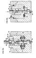
- the intermediate billet 36 is placed in a second die 42, which includes a movable die section 44 and a stationary die section 45.
- Die section 44 is spring biased upward into an initial position, shown in Fig. 3(a), by means of compression springs 46 which are seated within recesses 48 in movable die section 44 and opposing recesses 50 in the stationary die section. 45 of the second die.
- the movable die section 44 is free to move vertically within the opening 51 defined by stationary die section 45.
- the stationary die section 45 includes a shoulder 52 which provides a means for contacting the movable die section to prevent upward movement beyond the initial position.
- the movable die section 44 defines a billet receiving die opening 54 into which the intermediate billet is placed.
- An upper portion 56 of the die opening has an inside diameter substantially equal to the first diameter 0 1 and a lower portion 58 of the die opening has an inside diameter substantially equal to the second diameter D 2 .
- the first cylindrical portion 35 of the intermediate billet 36 which will ultimately form the first cylindrical portion 12 (Fig. 1) of the connector is positioned in the upper portion 56 of the die and the cylindrical portion 40 of reduced diameter of intermediate billet 36 is positioned in the lower portion 58 of the die.
- An extrusion drive member comprising finish punch 60, is then lowered, as shown in Fig. 3(b) such that the tip portion 62 of the punch 60 extends into recess 14 of the intermediate billet.
- the finish punch 60 applies pressure to the movable die section 44 through the intermediate billet 36, moving the intermediate billet 36 and the movable die section 44 downward, as shown in Fig. 3(b).
- This downward movement of the section 44 forces the portion 40 of the intermediate billet 36 over an upper portion 63 of a stationary punch 64 which is positioned within the die opening 54.
- the portion 40 is forward extruded over the portion 63, thereby forming the second cylindrical portion 16 (Fig. 1) of the connector 10.
- the shape of the portion 63 is precisely that desired for the recess 18 of the connector and may therefore include sections of differing diameters, and that the punch 64 further includes a lower portion 65 which extends completely across the die cavity 54.
- finish punch 60 is raised, as shown in Fig. 3(c), and, as a consequence, compression springs 46 raise the movable die section 44 and the finished connector 10 simultaneously therewith to the initial position of the movable die section.
- the stationary punch 64 which is attached to knockout cylindrical shaft 66, is also raised at the same time.
- the finish punch 60 is then retracted out of contact with the finished connector 10. Finally, the stationary punch 64 is raised further, as shown in Fig. 3(d), overcoming the frictional engagement between the exterior surface of the connector 10 and the interior surface of the movable die section 44. Connector 10 is thus ejected from the second die and the article forming method is completed.
- ductile metal it is intended to refer to copper, copper alloys, and other metals and metal alloys having sufficient ductility to be extruded.
Landscapes
- Engineering & Computer Science (AREA)
- Mechanical Engineering (AREA)
- Manufacturing & Machinery (AREA)
- Forging (AREA)
Claims (10)
Applications Claiming Priority (2)
| Application Number | Priority Date | Filing Date | Title |
|---|---|---|---|
| US06/338,804 US4416141A (en) | 1982-01-11 | 1982-01-11 | Method and apparatus for forming an electrical connector |
| US338804 | 1982-01-11 |
Publications (2)
| Publication Number | Publication Date |
|---|---|
| EP0086036A1 EP0086036A1 (de) | 1983-08-17 |
| EP0086036B1 true EP0086036B1 (de) | 1986-07-30 |
Family
ID=23326238
Family Applications (1)
| Application Number | Title | Priority Date | Filing Date |
|---|---|---|---|
| EP83300132A Expired EP0086036B1 (de) | 1982-01-11 | 1983-01-10 | Verfahren und Vorrichtung zur Formung eines zylindrischen Stückes, insbesondere eines elektrischen Verbindungsgliedes |
Country Status (4)
| Country | Link |
|---|---|
| US (1) | US4416141A (de) |
| EP (1) | EP0086036B1 (de) |
| CA (1) | CA1186875A (de) |
| DE (1) | DE3364789D1 (de) |
Families Citing this family (38)
| Publication number | Priority date | Publication date | Assignee | Title |
|---|---|---|---|---|
| DE3203438A1 (de) * | 1982-02-02 | 1983-08-11 | Motomak Motorenbau, Maschinen- u. Werkzeugfabrik, Konstruktionen GmbH, 8070 Ingolstadt | Verfahren zur herstellung einer metallmuffe aus einem zylindrischen rohrabschnitt |
| JPS6427735A (en) * | 1987-07-22 | 1989-01-30 | Nitto Kohki Co | Heading method for hollow part |
| US4945749A (en) * | 1989-10-30 | 1990-08-07 | General Motors Corporation | Cold forming dies and cold forming process |
| ES2137187T3 (es) * | 1991-05-16 | 1999-12-16 | Aeroquip Corp | Aparato formador con precision, metodo y articulo. |
| US5296317A (en) * | 1992-09-03 | 1994-03-22 | Water Gremlin Co. | High torque battery terminal and method of making same |
| US5373720A (en) * | 1992-09-03 | 1994-12-20 | Water Gremlin Company | Method of making battery terminal with necked flange |
| US5632173A (en) * | 1995-05-17 | 1997-05-27 | Tulip Corporation | Apparatus and method for cold forming a ring on a lead alloy battery terminal |
| US5791183A (en) * | 1995-05-17 | 1998-08-11 | Tulip Corporation | Apparatus and method for cold forming a ring on a lead alloy battery terminal including an anti-torque structure |
| US5606887A (en) * | 1995-06-02 | 1997-03-04 | Tulip Corporation | Apparatus and method for cold forming an L-shaped lead alloy battery terminal |
| US5655400A (en) * | 1995-06-02 | 1997-08-12 | Tulip Corporation | Progressive die apparatus and method for making a lead alloy battery terminal |
| JPH0953689A (ja) * | 1995-08-18 | 1997-02-25 | Mitsubishi Electric Corp | 遊星歯車減速機構およびその遊星歯車用支持ピンの加工方法 |
| US6085405A (en) * | 1998-09-15 | 2000-07-11 | Kao; Cheng-Hsien | Method of fabricating a handlebar stem for a bicycle |
| US6173632B1 (en) * | 1998-11-23 | 2001-01-16 | Semiconductor Technologies & Instruments, Inc. | Single station cutting apparatus for separating semiconductor packages |
| US6571452B1 (en) * | 1999-01-19 | 2003-06-03 | Barsplice Products, Inc. | Method of making steel couplers for joining concrete reinforcing bars |
| JP4147704B2 (ja) * | 1999-10-21 | 2008-09-10 | 株式会社デンソー | スパークプラグ用主体金具の製造方法 |
| DE10047467C5 (de) * | 2000-09-21 | 2009-08-06 | Schuler Pressen Gmbh & Co. Kg | Vorrichtung und Verfahren zum Umformen, insbesondere mit hydraulischer Schließvorrichtung |
| WO2004098807A1 (en) * | 2000-11-21 | 2004-11-18 | Barsplice Products, Inc. | Method of making steel couplers for joining concrete reinforcing bars |
| JP2003019538A (ja) * | 2001-07-04 | 2003-01-21 | Denso Corp | スパークプラグ用主体金具の製造方法 |
| US6701998B2 (en) | 2002-03-29 | 2004-03-09 | Water Gremlin Company | Multiple casting apparatus and method |
| US7163763B2 (en) | 2002-06-04 | 2007-01-16 | Tulip Corporation | Cold formed battery terminal |
| US6902095B2 (en) * | 2003-07-03 | 2005-06-07 | Water Gremlin Company | Two part cold formed battery terminal |
| US7338539B2 (en) | 2004-01-02 | 2008-03-04 | Water Gremlin Company | Die cast battery terminal and a method of making |
| US8701743B2 (en) | 2004-01-02 | 2014-04-22 | Water Gremlin Company | Battery parts and associated systems and methods |
| CN100349687C (zh) * | 2004-08-08 | 2007-11-21 | 湖北汽车工业学院 | 点焊电极表面电火花熔敷涂层用的熔敷棒及其制备方法 |
| US7538294B2 (en) * | 2005-05-17 | 2009-05-26 | Huys Industries Limited | Welding electrode and method |
| US20090282952A1 (en) * | 2008-05-14 | 2009-11-19 | Potzu Forging Co., Ltd. | Cold forged stainless tool and method for making the same |
| US20090325428A1 (en) * | 2008-06-30 | 2009-12-31 | General Electric Company | Flexible to rigid cable barrel splice |
| US20100071649A1 (en) * | 2008-09-23 | 2010-03-25 | Eaton Corporation | Ball plunger for use in a hydraulic lash adjuster and method of making same |
| EP3059785B1 (de) | 2009-04-30 | 2019-08-07 | Water Gremlin Company | Batterieteile mit halte- und abdichtungselementen |
| IT1400606B1 (it) * | 2010-06-18 | 2013-06-14 | Bonaiti S P A | Procedimento, particolarmente per la produzione di terminali per resistenze elettriche, e terminale ottenuto. |
| US9748551B2 (en) | 2011-06-29 | 2017-08-29 | Water Gremlin Company | Battery parts having retaining and sealing features and associated methods of manufacture and use |
| CN102319757B (zh) * | 2011-08-18 | 2013-11-20 | 中国兵器工业第五二研究所 | 镁合金变截面筒形件的复合挤压变形制备方法 |
| US9954214B2 (en) | 2013-03-15 | 2018-04-24 | Water Gremlin Company | Systems and methods for manufacturing battery parts |
| DE102016119656A1 (de) * | 2016-10-14 | 2018-05-03 | Bremi Fahrzeug-Elektrik Gmbh + Co. Kg | Verfahren zum Herstellen eines Kabelschuhs und Kabelschuh zum elektrischen Verbinden eines Kabels mit einem stromführenden Element |
| CN106670249B (zh) * | 2017-01-03 | 2018-08-28 | 中国兵器科学研究院宁波分院 | 带法兰凸缘轮辋挤扩成形方法 |
| CN108927416B (zh) * | 2018-07-09 | 2019-07-23 | 中国兵器工业第五九研究所 | 一种开放内型正反挤压复合成形方法 |
| MX2021006454A (es) | 2018-12-07 | 2021-07-02 | Water Gremlin Co | Partes de bateria que tienen barreras contra acidos sin solventes y sistemas y metodos asociados. |
| CN112439802A (zh) * | 2020-11-03 | 2021-03-05 | 中国兵器工业第五九研究所 | 具有内凸缘结构的筒形类构件的挤压成型方法 |
Family Cites Families (18)
| Publication number | Priority date | Publication date | Assignee | Title |
|---|---|---|---|---|
| US1702278A (en) * | 1928-05-18 | 1929-02-19 | Simons Abraham | Method of making seamless containers |
| US2583270A (en) * | 1947-08-18 | 1952-01-22 | Lynall Ezra Herbert | Production of tubular rivets and similar articles |
| US2891298A (en) * | 1954-04-07 | 1959-06-23 | American Radiator & Standard | Method of cold shaping partitioned tubular steel articles |
| GB778466A (en) * | 1954-11-24 | 1957-07-10 | Oreste Flavio Alfredo Biginell | Method of, and apparatus for, producing hollow metal parts by extrusion |
| US3122831A (en) * | 1958-02-27 | 1964-03-03 | Textron Inc | Method of manufacture of metal articles |
| US3101534A (en) * | 1958-06-30 | 1963-08-27 | Textron Inc | Method of producing wrist pins or similar articles |
| US3186209A (en) * | 1960-04-14 | 1965-06-01 | Nat Machinery Co | Method of cold forming an elongated hollow article |
| US3188849A (en) * | 1961-09-12 | 1965-06-15 | Nat Machinery Co | Method and apparatus for multiple upsetting |
| DE1402775A1 (de) * | 1961-11-02 | 1968-10-31 | Karl Sieber | Verfahren zur Herstellung von napffoermigen Hohlkoerpern aus massiven Rohlingen |
| US3197857A (en) * | 1962-12-21 | 1965-08-03 | Nippert Electric Products Comp | Method of producing cup-shaped conductive semi-conductor housing |
| US3494168A (en) * | 1968-01-18 | 1970-02-10 | Robert W Williamson | Forming tool |
| US3589164A (en) * | 1969-03-11 | 1971-06-29 | Verson Allsteel Press Co | Method and apparatus for extruding double-ended metal extrusions |
| US4061013A (en) * | 1976-09-29 | 1977-12-06 | John Kuc | Method of forming socket wrenches |
| US4071947A (en) * | 1976-12-13 | 1978-02-07 | The Nippert Company | Bimetal resistance welding electrode and method for making |
| GB1584292A (en) * | 1977-10-20 | 1981-02-11 | Nii Ex I Avtomobil Elektroobor | Extrusion |
| US4166373A (en) * | 1977-12-27 | 1979-09-04 | Braun Engineering Company | Method of cold forming |
| US4238949A (en) * | 1978-08-28 | 1980-12-16 | The General Tire & Rubber Company | Process and apparatus for making metal outers and inners |
| US4291568A (en) * | 1979-08-27 | 1981-09-29 | Veeder Industries Inc. | Method of forming socket wrenches |
-
1982
- 1982-01-11 US US06/338,804 patent/US4416141A/en not_active Expired - Lifetime
- 1982-12-21 CA CA000418208A patent/CA1186875A/en not_active Expired
-
1983
- 1983-01-10 EP EP83300132A patent/EP0086036B1/de not_active Expired
- 1983-01-10 DE DE8383300132T patent/DE3364789D1/de not_active Expired
Also Published As
| Publication number | Publication date |
|---|---|
| EP0086036A1 (de) | 1983-08-17 |
| US4416141A (en) | 1983-11-22 |
| DE3364789D1 (en) | 1986-09-04 |
| CA1186875A (en) | 1985-05-14 |
Similar Documents
| Publication | Publication Date | Title |
|---|---|---|
| EP0086036B1 (de) | Verfahren und Vorrichtung zur Formung eines zylindrischen Stückes, insbesondere eines elektrischen Verbindungsgliedes | |
| US7013696B2 (en) | Method of making a flanged tubular metallic part | |
| US5373720A (en) | Method of making battery terminal with necked flange | |
| EP0087911A1 (de) | Verfahren zur Herstellung einer Widerstandsschweisselektrode | |
| EP0404570B1 (de) | Verfahren zur Herstellung eines Hohlkörpers | |
| US3197857A (en) | Method of producing cup-shaped conductive semi-conductor housing | |
| JPS6035487A (ja) | スパ−クプラグシエルの成形方法 | |
| JP3534779B2 (ja) | 抵抗溶接用電極及びその製造方法 | |
| US3377700A (en) | Method of making electrical contact member | |
| US4575343A (en) | Bimetal electrode and method of making same | |
| US4695759A (en) | Method for producing a composite center electrode and an electrode | |
| US4606730A (en) | Bimetal electrodes for spark plugs or the like and method of making same | |
| CA1169237A (en) | Production of electrodes | |
| EP0220031A2 (de) | Schmiedeverfahren und -vorrichtung | |
| US4706383A (en) | Electrical contact assembly with composite contact construction | |
| US2874460A (en) | Process for manufacturing shells for spark plugs and the like | |
| CA1268020A (en) | Method for producing a composite center electrode for spark plug | |
| US4585421A (en) | Method of making copper-clad bimetal electrodes for spark plugs | |
| GB2076706A (en) | Producing a composite center electrode | |
| US4446618A (en) | Process for the production of bi-metallic contact rivets | |
| CA2459031A1 (en) | High torque battery terminal and method of making same | |
| JPS6355381B2 (de) | ||
| JP3471410B2 (ja) | スパークプラグ用主体金具の製造方法 | |
| US4744502A (en) | Process for the production of tri-metallic contact rivets | |
| JP2700304B2 (ja) | 圧着又は圧縮端子の製造方法 |
Legal Events
| Date | Code | Title | Description |
|---|---|---|---|
| PUAI | Public reference made under article 153(3) epc to a published international application that has entered the european phase |
Free format text: ORIGINAL CODE: 0009012 |
|
| AK | Designated contracting states |
Designated state(s): BE CH DE FR GB LI NL |
|
| 17P | Request for examination filed |
Effective date: 19840214 |
|
| GRAA | (expected) grant |
Free format text: ORIGINAL CODE: 0009210 |
|
| AK | Designated contracting states |
Kind code of ref document: B1 Designated state(s): BE CH DE FR GB LI NL |
|
| REF | Corresponds to: |
Ref document number: 3364789 Country of ref document: DE Date of ref document: 19860904 |
|
| ET | Fr: translation filed | ||
| PLBE | No opposition filed within time limit |
Free format text: ORIGINAL CODE: 0009261 |
|
| STAA | Information on the status of an ep patent application or granted ep patent |
Free format text: STATUS: NO OPPOSITION FILED WITHIN TIME LIMIT |
|
| 26N | No opposition filed | ||
| REG | Reference to a national code |
Ref country code: GB Ref legal event code: 732 |
|
| PGFP | Annual fee paid to national office [announced via postgrant information from national office to epo] |
Ref country code: FR Payment date: 19951213 Year of fee payment: 14 |
|
| PGFP | Annual fee paid to national office [announced via postgrant information from national office to epo] |
Ref country code: NL Payment date: 19951218 Year of fee payment: 14 |
|
| PGFP | Annual fee paid to national office [announced via postgrant information from national office to epo] |
Ref country code: GB Payment date: 19951228 Year of fee payment: 14 Ref country code: DE Payment date: 19951228 Year of fee payment: 14 |
|
| PGFP | Annual fee paid to national office [announced via postgrant information from national office to epo] |
Ref country code: BE Payment date: 19951229 Year of fee payment: 14 |
|
| PGFP | Annual fee paid to national office [announced via postgrant information from national office to epo] |
Ref country code: CH Payment date: 19960123 Year of fee payment: 14 |
|
| PG25 | Lapsed in a contracting state [announced via postgrant information from national office to epo] |
Ref country code: GB Effective date: 19970110 |
|
| PG25 | Lapsed in a contracting state [announced via postgrant information from national office to epo] |
Ref country code: LI Effective date: 19970131 Ref country code: CH Effective date: 19970131 Ref country code: BE Effective date: 19970131 |
|
| BERE | Be: lapsed |
Owner name: THE NIPPERT CY Effective date: 19970131 |
|
| PG25 | Lapsed in a contracting state [announced via postgrant information from national office to epo] |
Ref country code: NL Effective date: 19970801 |
|
| GBPC | Gb: european patent ceased through non-payment of renewal fee |
Effective date: 19970110 |
|
| REG | Reference to a national code |
Ref country code: CH Ref legal event code: PL |
|
| PG25 | Lapsed in a contracting state [announced via postgrant information from national office to epo] |
Ref country code: FR Effective date: 19970930 |
|
| NLV4 | Nl: lapsed or anulled due to non-payment of the annual fee |
Effective date: 19970801 |
|
| PG25 | Lapsed in a contracting state [announced via postgrant information from national office to epo] |
Ref country code: DE Effective date: 19971001 |
|
| REG | Reference to a national code |
Ref country code: FR Ref legal event code: ST |