EP0085964A2 - Roof-rack - Google Patents
Roof-rack Download PDFInfo
- Publication number
- EP0085964A2 EP0085964A2 EP83101071A EP83101071A EP0085964A2 EP 0085964 A2 EP0085964 A2 EP 0085964A2 EP 83101071 A EP83101071 A EP 83101071A EP 83101071 A EP83101071 A EP 83101071A EP 0085964 A2 EP0085964 A2 EP 0085964A2
- Authority
- EP
- European Patent Office
- Prior art keywords
- roof rack
- roof
- support elements
- rack according
- brackets
- Prior art date
- Legal status (The legal status is an assumption and is not a legal conclusion. Google has not performed a legal analysis and makes no representation as to the accuracy of the status listed.)
- Withdrawn
Links
Images


Classifications
-
- B—PERFORMING OPERATIONS; TRANSPORTING
- B60—VEHICLES IN GENERAL
- B60R—VEHICLES, VEHICLE FITTINGS, OR VEHICLE PARTS, NOT OTHERWISE PROVIDED FOR
- B60R9/00—Supplementary fittings on vehicle exterior for carrying loads, e.g. luggage, sports gear or the like
- B60R9/04—Carriers associated with vehicle roof
- B60R9/042—Carriers characterised by means to facilitate loading or unloading of the load, e.g. rollers, tracks, or the like
-
- B—PERFORMING OPERATIONS; TRANSPORTING
- B60—VEHICLES IN GENERAL
- B60R—VEHICLES, VEHICLE FITTINGS, OR VEHICLE PARTS, NOT OTHERWISE PROVIDED FOR
- B60R9/00—Supplementary fittings on vehicle exterior for carrying loads, e.g. luggage, sports gear or the like
- B60R9/08—Supplementary fittings on vehicle exterior for carrying loads, e.g. luggage, sports gear or the like specially adapted for sports gear
Definitions
- the invention relates to a roof rack for vehicles, in particular for transporting at least one surfboard, with at least two brackets running across the roof and attachable to the gutter or the doors.
- the object of the present invention is therefore to create a roof rack in which a surfboard can be loaded and unloaded by a person even without outside help.
- This object is achieved in that on each of the brackets an element is slidably supported along the same, each carrying an articulated connection or in cooperation with elements of the bracket forms an articulated connection, around which at least one each extends over the associated bracket, in essentially elongated support element is pivotable such that it extends down the side of the vehicle when the element is displaced in the direction of the free end of the support element up to the edge of the associated bracket, and at least one of which can be locked in the outer region of the bracket when the elements are on the brackets are pushed back.
- the support elements are preferably rod-shaped mig formed and expediently have a flat surface facing upwards.
- the support elements are expediently connected to one another by at least one longitudinal strut. The arrangement becomes particularly stable if a longitudinal strut is attached to the outer edge of the support elements and at least one further longitudinal strut in the central region of the support elements.
- the stirrups are tubular, with a continuous slot on their upper area, through which at least the upper edge of the respective support element protrudes.
- Brackets have proven to be particularly favorable which are rectilinear and cylindrical in the area running over the roof and preferably have a rectangular cross section, the longitudinal slot being in each case provided on the upper side and the two edges of the longitudinal slot preferably being bent inwards.
- the support elements are designed as rods with mutually parallel side walls, which are adjacent to one of their ends in their lower region are provided with a widening, which prevents the rods in this area from being pulled upwards out of the longitudinal slots. Together with the edges of the longitudinal slots, these widenings form the articulated connections.
- the widening is expediently formed by a pin fastened to the underside of the rods, the free ends of which protrude laterally beyond the side walls of the rods on both sides.
- a pin is expediently provided which penetrates the brackets transversely.
- the undersides of the rods forming the support elements slide out on this pin when the support elements are pulled out of the brackets.
- releasable locking means are also provided, for example in the form of insertable pins or screws, which, in cooperation with the pins and the pin located on the underside of the rods at their opposite ends, limit the pivoting movement, which is sought when the Support elements should form the roof area of a tent canopy.
- An effective locking of the roof rack for the driving condition can be achieved, on the one hand, by providing a tab adjacent to the free ends of the support elements, which, when the elements are retracted, extend down to below the bracket and each have a through hole.
- the through holes are aligned and serve to receive the mast from the surfboard.
- a pin is expediently fitted in the outer region of the bracket, on which an inwardly facing, essentially horizontal slot in the tabs or an outwardly facing corresponding slot in the elements can be pushed. The assumed end positions of the displacement are thereby additionally secured.
- a simple and also theft-proof mounting of the surfboard on the roof rack is obtained if a hole is provided in at least one of the longitudinal struts, through which a screw can be passed, which can be screwed into a bolt that can be inserted into the sword box of the surfboard.
- the one with a head Bolts prevented from falling through by the sword case expediently have a polygonal cross section which prevents the bolt from being unscrewed from above. Since the distance between the roof of the vehicle and the lower edge of the screw is so small that the screw cannot be unscrewed from the bolt when the roof rack is brought into the position intended for transport, the bolt is formed in the lower area that it is spread out by screwing in the screw.
- the longitudinal strut which connects the free ends of the support elements to one another, is rotatably mounted or provided with a rotatably mounted slide tube, at least one pawl being detachably attached to the ends of these rotatable parts can be brought into engagement with an abutment on the corresponding bracket.
- Accidental displacement of the support elements or lifting at the free ends is particularly effectively prevented here if the pawl is spring-loaded in the direction of the closed position.
- At least one central rod which projects essentially perpendicularly from the longitudinal strut and is preferably detachably fastened to the longitudinal strut, serves to rotate the longitudinal strut.
- the locking device described above proves to be particularly suitable for motorhomes in which the roof rack is very high.
- This configuration further enables an extremely simple design of an awning, the central pole serving as a strut seated on the floor. Additional brackets attached to the free ends of the support elements and / or to the longitudinal strut allow the attachment of additional struts to stabilize the awning.
- the free ends of the brackets are designed so that they can be inserted into a roof gutter of the motor vehicle, hooks engaging around the gutter or edge of the door, which can be determined by a screw on the bracket, and the screw receives a bore passing through it, into which an angled rigid bracket can be inserted at one end, the other end of which is secured by inserting it between the door and door frame of the vehicle and then closing the vehicle door .
- the roof rack can also be used for the transport of skis if elements carrying joint connections are used on the brackets and the distance between the support elements and the brackets is selected so that skis can be clamped between them. It is furthermore expedient if the top of the support elements and / or the inside of the contact areas and / or the underside of the support elements or the top of the brackets are provided with an elastically flexible protective layer so that the objects carried on the roof rack are not loaded during loading or being chafed while driving. The attachment of padding to the lower edge of the straps prevents possible damage to the vehicle side wall if the roof rack is overloaded during loading or if the unloading process is carried out improperly.
- a cover is attached to the support elements and / or the longitudinal struts, which cover can consist rigidly of elastically resilient material such as hard PVC and is preferably releasably attached.
- the cover can also serve as the roof of an awning, which can be completed by attaching wall parts of an awning to the support elements and / or the longitudinal section, for example by means of zippers, push buttons or Velcro fasteners.
- the wall parts can also be designed such that they can be rolled up. The same applies to the cover.
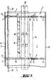
- a roof rack 2 is fastened, on which a surfboard 3 and possibly another surfboard 4 are fastened.
- the roof rack 2 consists of two brackets 5 and 6 with a horizontal area running across the roof and downward bent end areas 7 and 8, with their free ends in the gutters 9 and 10 of the vehicle roof 1.
- Sleeves 11 and 12 are slidably supported on the brackets along the rectilinear region of the brackets 5 and 6.
- the sleeves contain a laterally occupied longitudinal slot 13.
- an upstanding projection 14, 15 is attached, which is at its front, laterally to the end of the Sleeves 11 and 12 occupy the end of a joint 16, 17 in which the ends of tubes 18 and 19, which form the support elements for the surfboard 3, are pivotally mounted.
- the tubes 18 and 19 extend parallel to the brackets 5 and 6 from the sleeves 11 and 12 to the end of the rectilinear region of the brackets, in which they merge into the end regions 7.
- the tubes carry bends 20 and 21 which protrude vertically upwards at right angles, which form vertical contact areas for the surfboard 3.
- a downwardly projecting tab 23 is fastened which, in the position assumed in FIG.
- the tabs 23 contain a through hole 24, the diameter of which corresponds to that of a mast 25 to be transported with the surfboard. If, as strength by the hatching of F. 1 indicated that in addition to the surfboard 3 an overlying surfboard 4 is to be transported, the tab 23 has a further area designated 23a, which has a further bore for receiving a second mast, which of course also, as indicated by reference number 21a, extend the side turns further up.
- the tabs 23 also contain a longitudinal slot 26 which runs parallel to the brackets 5 and 6 and which receives a pin 27 which projects rearwards in the end region of the straight part of the brackets 5 and 6.
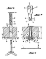
- a hole 28 with a small diameter is made in the tabs 23, which, in the position of the roof rack 1 assumed in FIG. 1, lies opposite a longitudinal hole 29 in the bracket 5 or 6. Details of this configuration are best known 7 and 8 can be seen. It can be seen there that a bracket 30 of a lock 31 can be inserted through the bores 28 and 29 when the pin 27 assumes the end position in the longitudinal slot 26 connected pin 33 secured through a hole 34 through the mast 25. As soon as the bracket 30 is passed through the bores 28 and 29 and the end ring 32 and the lock 31 is closed, the mast can no longer be removed without authorization and the roof rack can no longer be moved out of the position shown in FIG. 1.
- the two tubes 18 and 19 serving as support elements are connected to one another approximately in the region of their center by a longitudinal strut 35 which contains a series of bores 36. These bores, together with the fastening mechanism shown in FIGS. 4 to 6, permit theft-proof mounting of the surfboard 3 on the roof rack 1.
- the fastening mechanism consists of a bolt 37 which contains flats 38 in its upper region, which are just designed so that that the bolt can be inserted into a sword case 39 of the surfboard 3, as shown in FIG. 4, with the surfboard 3 lying on the tubes 18 and 19.
- the flats 38 prevent the bolt 37 from rotating in the sword case 39.
- the bolt 37 contains longitudinal grooves 40, 41, 42 and 43 and an end flange 44. It also has an internal thread 45 in its interior.
- a screw 47 is screwed into the internal thread 45 of the bolt 37 screwed in, the E whereby nd- portion of the bolt expands, so that the flange 44 at the lower edges of the bore 36, as shown in FIG. 5 can be seen, is supported.
- the length of the screw 47 is chosen to be greater than the height h, which in FIG. 5 indicates the distance between the upper edge of the roof 1 and the lower edge of the screw in the screwed-in state. In this way it is ensured that the screw 47 can only be completely loosened when the roof rack is in the position shown in FIG. 2. This means that in the position of the roof rack shown in Fig.
- the space between the brackets 5 and 6 and the tubes 18 and 19 can, as indicated in FIGS. 1 and 3, also be used to hold skis 49 which can be clamped in between. It is advisable to provide the top of the brackets 5 and 6 and / or the underside of the tubes 18 and 19 with an elastic surface, which also compensates for certain differences in thickness. However, these elastic layers are not shown in the drawings. It goes without saying that the skis must be inserted and removed before the roof rack is transferred from the position shown in FIG. 1 to the position shown in FIG. 2, since otherwise the sleeves 11 or 12 cannot be moved undisturbed.
- the tubes 18 and 19 can be designed to be telescopically extendable, as indicated by a dot-dash line in FIG. 2.
- the tubes slide on a cylindrical rod 51 fastened in the region of the joints 16 and 17, which carries at its front end a projection 52 reaching as far as the wall of the tubes.
- a ring 53 is inserted, the central bore of which is displaceable along the rod 51.
- a weight compensation spring 54 is clamped, which is compressed during the transition of the roof rack from the position shown in FIG. 1 to the position shown in FIG. 2 and supports the lifting of the load in the reverse process.
- Fig. 9 an additional security system is shown, which prevents unauthorized removal of the roof rack.
- a threaded bore 55 is provided slightly above the free end, into which a fastening screw 56 can be screwed.
- the fastening screw 56 extends loosely through a bore 57 in the upper end of a hook 58 which is supported with its upper end 59 in a bead 60 provided above the threaded bore 55 in the end region 7.
- the lower end 62 of the hook 58 engages around the gutter 9, wherein it is pressed against the fastening screw 56 by tightening it.
- a wire-shaped stiff angled bracket 63 is inserted with its upper end through a transversely through the fastening screw 56 bore 64 which with its inwardly projecting free En de between a door 65 and a door frame 66 can be inserted and clamped therein.
- the bracket 63 includes a head 67 at its upper end, which prevents the bracket from being pushed downward by force through the bore 64. It is also possible to attach an anchor 68 to the free end clamped in the area between door 65 and door frame 66, which anchor can be rotated or bent about the longitudinal axis of the bracket and additionally counteracts violent removal of the bracket 63.
- the bracket 6 is in this case divided into two tubes 6a and 6b, which are plugged together by a U-profile tube 69 inserted in both free ends.
- the tubes 6a and 6b can be brought closer to or removed from one another.
- a cover 74 is also indicated, which can be solid and serves to protect the skis in the event of transport.
- the cover 74 it is also possible to manufacture the cover 74 from an elastically flexible, possibly stretchable material and to make the cover removable.
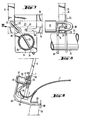
- the brackets 5, 6 here consist at least in the region running straight over the roof 1 from tubes 8 0 , which, as can be seen from the sectional view of FIG. 15, have a rectangular cross section and have continuous longitudinal slots 81 on their top, in the area of the Edge, as indicated by reference numeral 81a, is bent inwards so that it forms a guide surface.
- Straight tubes 82 are guided in the tubes 8o, which have a rectangular cross section and, as can be seen in FIG. 15, can be hollow.
- the bars 82 have two mutually parallel side walls 83 and 84 which run parallel to the longitudinal slot 81, the inwardly bent edges 81a forming a guide for the bars 82.
- the upper ends of the rods 82 protrude above the pipes 8o.
- a pin 85 is attached transversely to the longitudinal direction of the rods 82 in such a way that the free ends of the pin 85 run approximately perpendicular to the longitudinal slot 81 to close reach to the inner wall of the pipes 8o, but with so much play that when the rods 82 are pulled out from the view from FIG.
- the pin 85 prevents the rods 82 from being able to be lifted up out of the longitudinal slots 81 at their right-hand ends as seen in FIG. 16. From the point of view 16 ends of the stirrups 5, 6 through the tubes 8o each penetrate a pin 86, the upper edge of which lies in such a way that the bars 82, as indicated by dashed lines in FIG. 17, rest on their underside and slide along as they are pulled out. Above the pin 86, shifted somewhat inward relative to this, an optionally insertable locking member 87 is provided laterally to the longitudinal slot 81 in the tube 80, which can be formed by a screw or a bolt. As can be seen from FIG.
- the locking member 87 prevents the rods 82 from being able to be pulled out completely, as a result of which the maximum inclination of the rods 82 with respect to the horizontal is limited.
- This state is shown in Fig. 14 with solid lines.
- the bars 82 form the lateral boundaries for the roof of an awning formed from them, as shown in FIG. 13.
- the rods 82 can be pulled further outwards, so that, as indicated by the dash-dotted line in FIG. 14, the rods can be tilted even more so that they assume an end position, as shown in FIG .2 is shown and how you need it to unload the surfboard.
- Reference number 88 indicates a connecting rail which connects the right and left half of the brackets to one another in a manner known per se by means of screws 89 and 90.
- the bars 82 in the brackets 5 and 6 are connected to one another by means of two longitudinal struts 91 and 92 attached to the edge thereof, so that a firm, extendable, flat frame is formed which is guided in the longitudinal slots 81.
- a central strut 35 serves to hold surfboards.
- the longitudinal strut 91 While the longitudinal strut 91 is rigid, the longitudinal strut 92, which connects the free ends of the rods 82, is rotatably supported therein so that a pawl 93 rigidly connected to the longitudinal strut 92, which is attached adjacent to the end of the longitudinal strut 92, with this is rotatable.
- a pawl 93 In Fig.16 such a pawl is shown only in the bracket 5. However, it goes without saying that a corresponding one can also be attached to the bracket 6.
- the pawl 93 engages, as can be seen in FIG. 17, in a lug 94, which can be formed, for example, by the outwardly projecting end of the pin 86.
- a spring 95 carries the pawl 93 in the locked position and thus prevents the rods from slipping out unintentionally.
- a sleeve piece 96 is welded, which is provided with an internal thread, via which a central rod 97 can be screwed in, which serves as a lever arm for rotating the longitudinal strut 92 about its longitudinal axis and thus for unlocking the pawl 93.
- the central rod 97 carries at its end a foot part 98 with which the central rod 97 can be set up on the floor when the position shown in FIG. 13 has been assumed by the roof rack.
- further fastening options for additional struts can be provided, which serve to stabilize the awning.
- the frame formed between the rods 82 and the longitudinal struts 91 and 92 can be covered by means of a firm but resilient hard PVC cover, such as 74 for the partial covering in the embodiment shown in FIG is indicated.
- a tarpaulin cover 99 which can be wound up on a roll 100 when not required.
- the side walls of the awning, which are indicated with 1 0 1, 102, are fastened to the rods 82 or the longitudinal strut 92 in a known manner.
Abstract
Description
Die Erfindung betrifft einen Dachgepäckträger für Fahrzeuge, insbesondere zum Transport zumindest eines Surfbretts,mit zumindest zwei quer über das Dach verlaufenden und an der Dachrinne oder den Türen befestigbaren Bügeln.The invention relates to a roof rack for vehicles, in particular for transporting at least one surfboard, with at least two brackets running across the roof and attachable to the gutter or the doors.
Da der Surfsport überwiegend alleine ausgeübt wird und die Mehrzahl der Bevölkerung keine Möglichkeit hat, ihr Surfbrett dauernd an einem Seegrundstück zu belassen, besteht das Problem, das Surfboard alleine vom Transportmittel, vorzugsweise einem Kraftfahrzeug, ab- bzw. aufzuladen. Diese Vorgänge sind ohne fremde Hilfe nur schwer zu bewältigen. Dies bedeutet, daß man jeweils auf die Hilfe einer zweiten Person angewiesen ist.Since the surf sport is mainly practiced alone and the majority of the population has no way of leaving their surfboard permanently on a lake property, there is the problem of unloading or charging the surfboard from the means of transport, preferably a motor vehicle. These processes are difficult to manage without outside help. This means that you always need the help of a second person.
Der vorliegenden Erfindung liegt daher die Aufgabe zugrunde, einen Dachgepäckträger zu schaffen, bei dem ein Surfboard auch ohne fremde Hilfe von einer Person auf-und abgeladen werden kann. Diese Aufgabe wird erfindungsgemäß dadurch gelöst, daß auf jedem der Bügel ein Element längs desselben verschiebbar gehaltert ist, welches je eine Gelenkverbindung trägt bzw. im Zusammenwirken mit Elementen des Bügels eine Gelenkverbindung bildet, um die je zumindest ein sich über den zugehörigen Bügel erstreckendes, im wesentlichen längliches Auflageelement derart schwenkbar ist, daß es seitlich an dem Fahrzeug herabreicht, wenn das Element in Richtung des freien Endes des Auflageelements bis zum Rande des zugehörigen Bügels verschoben ist, und von denen zumindest eines im Außenbereich des Bügels arretierbar ist, wenn die Elemente auf den Bügeln zurückgeschoben sind. Die Auflageelemente sind vorzugsweise stabförmig ausgebildet und weisen zweckmäßigerweise eine ebene nach oben gekehrte Fläche auf. Zweckmäßigerweise sind die Auflageelemente durch zumindest eine Längsstrebe miteinander verbunden. Besonders stabil wird die Anordnung, wenn eine Längsstrebe am äußeren Rand der Auflageelemente und zumindest eine weitere Längsstrebe im Mittelbereich der Auflageelemente angebracht ist.The object of the present invention is therefore to create a roof rack in which a surfboard can be loaded and unloaded by a person even without outside help. This object is achieved in that on each of the brackets an element is slidably supported along the same, each carrying an articulated connection or in cooperation with elements of the bracket forms an articulated connection, around which at least one each extends over the associated bracket, in essentially elongated support element is pivotable such that it extends down the side of the vehicle when the element is displaced in the direction of the free end of the support element up to the edge of the associated bracket, and at least one of which can be locked in the outer region of the bracket when the elements are on the brackets are pushed back. The support elements are preferably rod-shaped mig formed and expediently have a flat surface facing upwards. The support elements are expediently connected to one another by at least one longitudinal strut. The arrangement becomes particularly stable if a longitudinal strut is attached to the outer edge of the support elements and at least one further longitudinal strut in the central region of the support elements.
Das Ablegen eines auf dem Dachgepäckträger zu transportierenden Gegenstandes, insbesondere eines Surfboards, bei seitlich am Kraftfahrzeug herabreichenden Auflageelementen wird dadurch erleichtert, daß an den freien Enden derselben vertikale nach oben ragende Anlagebereiche vorgesehen sind. Im Normalfalle sind diese lediglich an den Enden der Auflageelemente angebracht. Es kann jedoch auch zweckmäßig sein, die Anlagebereiche als durchlaufende Anlageflächen auszubilden.The storage of an object to be transported on the roof rack, in particular a surfboard, with support elements extending down the side of the motor vehicle is made easier by the fact that vertical upwardly projecting bearing areas are provided at the free ends thereof. In the normal case, these are only attached to the ends of the support elements. However, it can also be expedient to design the contact areas as continuous contact surfaces.
Gemäß einer besonders zweckmäßigen Ausführungsform der Erfindung sind die Bügel rohrförmig ausgebildet, wobei sie an ihrem oberen Bereich einen durchlaufenden Schlitz tragen, durch den zumindest die Oberkante des jeweiligen Auflageelements hinausragt. Als besonders günstig haben sich Bügel erwiesen, die in dem über das Dach verlaufenden Bereich gradlinig und zylindrisch sind sowie vorzugsweise einen Rechteckquerschnitt aufweisen, wobei der Längsschlitz jeweils an der Oberseite angebracht ist und die beiden Ränder des Längsschlitzes vorzugsweise nach innen umgebogen sind.According to a particularly expedient embodiment of the invention, the stirrups are tubular, with a continuous slot on their upper area, through which at least the upper edge of the respective support element protrudes. Brackets have proven to be particularly favorable which are rectilinear and cylindrical in the area running over the roof and preferably have a rectangular cross section, the longitudinal slot being in each case provided on the upper side and the two edges of the longitudinal slot preferably being bent inwards.
Bei dieser Konstruktion empfiehlt es sich besonders, daß die Auflageelemente als Stäbe mit zueinander parallelen Seitenwandungen ausgebildet sind, die benachbart zu dem einen ihrer Enden in ihrem unteren Bereich mit einer Verbreiterung versehen sind, welche verhindert, daß die Stäbe in diesem Bereich aus den Längsschlitzen nach oben herausziehbar sind. Diese Verbreiterungen bilden im Zusammenwirken mit den Rändern der Längsschlitze die Gelenkverbindungen. Zweckmäßigerweise wird die Verbreiterung von einem an der Unterseite der Stäbe befestigten Stift gebildet, dessen:freie Enden seitlich über die Seitenwandungen der Stäbe beidseits vorstehen.In this construction, it is particularly recommended that the support elements are designed as rods with mutually parallel side walls, which are adjacent to one of their ends in their lower region are provided with a widening, which prevents the rods in this area from being pulled upwards out of the longitudinal slots. Together with the edges of the longitudinal slots, these widenings form the articulated connections. The widening is expediently formed by a pin fastened to the underside of the rods, the free ends of which protrude laterally beyond the side walls of the rods on both sides.
An dem Übergangsbereich der Bügel, an dem diese von dem gerade über das Dach verlaufenden Bereich in Richtung auf das Dach nach unten umbiegen, ist zweckmäßigerweise ein Stift vorgesehen, der die Bügel quer durchsetzt. Die Unterseiten der die Auflageelemente bildenden Stäbe gleiten auf diesem Stift eben heraus, wenn die Auflageelemente aus den Bügeln herausgezogen werden.At the transition area of the brackets at which they bend downward from the area just running over the roof towards the roof, a pin is expediently provided which penetrates the brackets transversely. The undersides of the rods forming the support elements slide out on this pin when the support elements are pulled out of the brackets.
Im Bereich der Stifte sind des weiteren lösbare Arretiermittel vorgesehen, beispielsweise in Form von einsteckbaren Stiften oder Schrauben, die im Zusammenwirken mit den Stiften und dem an der Unterseite der Stäbe an deren entgegengesetztem Ende befindlichen Stift die Schwenkbewegung begrenzen, was dann angestrebt wird, wenn die Auflageelemente den Dachbereich eines Zeltvordaches bilden sollen.In the area of the pins releasable locking means are also provided, for example in the form of insertable pins or screws, which, in cooperation with the pins and the pin located on the underside of the rods at their opposite ends, limit the pivoting movement, which is sought when the Support elements should form the roof area of a tent canopy.
Eine wirksame Arretierung des Dachgepäckträgers für den Fahrtzustand läßt sich zum einen dadurch erreichen, daß benachbart zu den freien Enden der Auflageelemente je eine Lasche vorgesehen ist, die bei zurückgefahrenen Elementen bis unter die Bügel herabreichen und je eine Durchgangsbohrung aufweisen. Die Durchgangsbohrungen fluchten miteinander und dienen zur Aufnahme des Mastes von dem Surfboard. Wenn der Mast durch die Bohrungen hindurchgesteckt ist, verhindert er zum einen ein unbeabsichtigtes Nachaußenschieben der Auflageelemente, zum anderen deren Abheben nach oben. Zweckmäßigerweise ist hierbei ein Stift im Außenbereich der Bügel angebracht, auf dem ein nach innen weisender, im wesentlichen horizontaler Schlitz in den Laschen oder ein nach außen weisender entsprechender Schlitz in den Elementen aufschiebbar ist. Die jeweils angenommenen Endlagen der Verschiebung sind hierdurch zusätzlich gesichert. In einer Weiterbildung dieser Anordnung erhält man eine wirksame Diebstahlssicherung, indem man in der Lasche eine Bohrung anbringt, die mit einer entsprechenden Bohrung im Bügel ausrichtbar ist, so daß durch die beiden Bohrungen ein Bügel eines Schlosses hindurchsteckbar ist. Mittels eines mit einem Endring versehenen Stifts, der über den Endring auf den Bügel des Schlosses aufschiebbar und durch eine Bohrung im Mast hindurchführbar ist, läßt sich gleichzeitig der Mast gegen ein unbeabsichtigtes Verrutschen oder gegen Diebstahl sichern.An effective locking of the roof rack for the driving condition can be achieved, on the one hand, by providing a tab adjacent to the free ends of the support elements, which, when the elements are retracted, extend down to below the bracket and each have a through hole. The through holes are aligned and serve to receive the mast from the surfboard. On the one hand, if the mast is inserted through the bores, it prevents uncompromised intentionally pushing the support elements outwards, and secondly lifting them upwards. In this case, a pin is expediently fitted in the outer region of the bracket, on which an inwardly facing, essentially horizontal slot in the tabs or an outwardly facing corresponding slot in the elements can be pushed. The assumed end positions of the displacement are thereby additionally secured. In a further development of this arrangement, effective theft protection is obtained by making a hole in the tab which can be aligned with a corresponding hole in the bracket, so that a bracket of a lock can be inserted through the two holes. By means of a pin provided with an end ring, which can be pushed over the end ring onto the bracket of the lock and can be passed through a hole in the mast, the mast can at the same time be secured against unintentional slipping or against theft.
Falls große Aufladehöhen überwunden werden müssen, empfiehlt es sich, die Auflageelemente teleskopisch ausfahrbar zu gestalten und diese zweckmäßigerweise mit einer Gewichtsausgleichsfeder zu versehen, welche den Aufladevorgang unterstützt und beim Abladevorgang eine Bremswirkung ausübt.If large loading heights have to be overcome, it is advisable to make the support elements telescopically extendable and expediently to provide them with a weight compensation spring which supports the charging process and exerts a braking effect during the unloading process.
Eine einfache und zudem diebstahlssichere Halterung des Surfbretts auf dem Dachgepäckträger erhält man, wenn man in zumindest einer der Längsstreben eine Bohrung vorsieht, durch welche eine Schraube hindurchführbar ist, die in einen in den Schwertkasten des Surfbretts einsetzbaren Bolzen einschraubbar ist. Der mit einem Kopf an einem Durchfallen durch den Schwertkasten gehinderte Bolzen weist zweckmäßigerweise einen Mehrkantquerschnitt auf, der ein Herausdrehen des Bolzens von oben verhindert. Da der Abstand zwischen dem Dach des Fahrzeuges und der Unterkante der Schraube so gering bemessen ist, daß die Schraube auch nicht aus dem Bolzen herausdrehbar ist, wenn der Dachgepäckträger in die für den Transport vorgesehene Stellung gebracht ist, wird der Bolzen im unteren Bereich so ausgebildet, daß er durch das Einschrauben der Schraube aufgespreizt wird.A simple and also theft-proof mounting of the surfboard on the roof rack is obtained if a hole is provided in at least one of the longitudinal struts, through which a screw can be passed, which can be screwed into a bolt that can be inserted into the sword box of the surfboard. The one with a head Bolts prevented from falling through by the sword case expediently have a polygonal cross section which prevents the bolt from being unscrewed from above. Since the distance between the roof of the vehicle and the lower edge of the screw is so small that the screw cannot be unscrewed from the bolt when the roof rack is brought into the position intended for transport, the bolt is formed in the lower area that it is spread out by screwing in the screw.
Gemäß einer weiteren Alternative für die Verriegelung der Auflageelemente an den Bügeln wird die Längsstrebe, welche die freien Enden der Auflageelemente miteinander verbindet, drehbar gelagert oder mit einem drehbar gelagerten Uberschubrohr versehen, wobei an den Enden dieser drehbaren Teile zumindest eine Sperrklinke befestigt ist, die lösbar in Eingriff mit einem Widerlager an dem entsprechenden Bügel bringbar ist. Ein versehentliches Verschieben der Auflageelemente oder Anheben an den freien Enden wird hier besonders wirksam verhindert, wenn die Sperrklinke in Richtung auf die Schließstellung federbelastet ist. Zur Drehung der Längsstrebe dient zumindest eine im wesentlichen senkrecht von der Längsstrebe abstehende Mittelstange, welche vorzugsweise lösbar an der Längsstrebe befestigt ist. Im Zusammenhang mit dieser Mittelstange erweist sich die vorstehend beschriebene Arretierung als besonders geeignet für Reisemobile, bei denen der Dachgepäckträger sehr hoch liegt. Diese Ausgestaltung ermöglicht des weiteren eine äußerst einfache Ausbildung eines Vorzeltes, wobei die Mittelstange als auf dem Boden aufsitzende Strebe dient. An den freien Enden der Auflageelemente und/oder an der Längsstrebe angebrachte zusätzliche Halterungen ermöglichen die Befestigung weiterer Streben zur Stabilisierung des Vorzelts.According to a further alternative for locking the support elements on the brackets, the longitudinal strut, which connects the free ends of the support elements to one another, is rotatably mounted or provided with a rotatably mounted slide tube, at least one pawl being detachably attached to the ends of these rotatable parts can be brought into engagement with an abutment on the corresponding bracket. Accidental displacement of the support elements or lifting at the free ends is particularly effectively prevented here if the pawl is spring-loaded in the direction of the closed position. At least one central rod, which projects essentially perpendicularly from the longitudinal strut and is preferably detachably fastened to the longitudinal strut, serves to rotate the longitudinal strut. In connection with this center bar, the locking device described above proves to be particularly suitable for motorhomes in which the roof rack is very high. This configuration further enables an extremely simple design of an awning, the central pole serving as a strut seated on the floor. Additional brackets attached to the free ends of the support elements and / or to the longitudinal strut allow the attachment of additional struts to stabilize the awning.
Um des weiteren zu verhindern, daß der Dachgepäckträger mitsamt seinem Inhalt in unbefugter Weise von dem Kraftfahrzeug entfernt wird, werden die freien Enden der Bügel so ausgebildet, daß sie in eine Dachrinne des Kraftfahrzeuges einsetzbar sind, wobei Haken um die Dachrinne oder Türkante greifen, welche durch eine Schraube an dem Bügel feststellbar sind, und wobei die Schraube eine sie quer durchsetzende Bohrung erhält, in welche ein abgewinkelter steifer Bügel mit einem Ende einsteckbar ist, dessen anderes Ende durch Einschieben zwischen Tür und Türrahmen des Fahrzeuges und anschließendes Schließen der Fahrzeugtür gesichert ist.To further prevent the roof rack and its contents from being removed from the motor vehicle in an unauthorized manner, the free ends of the brackets are designed so that they can be inserted into a roof gutter of the motor vehicle, hooks engaging around the gutter or edge of the door, which can be determined by a screw on the bracket, and the screw receives a bore passing through it, into which an angled rigid bracket can be inserted at one end, the other end of which is secured by inserting it between the door and door frame of the vehicle and then closing the vehicle door .
Der Dachgepäckträger läßt sich auch zum Transport von Skiern verwenden, wenn auf den Bügeln Gelenkverbindungen tragende Elemente verwendet sind und der Abstand zwischen den Auflageelementen und den Bügeln so gewählt wird, daß zwischen ihnen Skier einklemmbar sind. Es ist des weiteren zweckmäßig, wenn die Oberseite der Auflageelemente und/oder die Innenseite der Anlagebereiche und/ oder die Unterseite der Auflageelemente bzw. die Oberseite der Bügel mit einer elastisch nachgiebigen Schutzschicht versehen sind, damit die auf dem Dachgepäckträger beförderten Gegenstände nicht während des Aufladens oder während der Fahrt durch Scheuern verletzt werden. Die Anbringung von einer Polsterung an der Unterkante der Laschen verhindert eine mögliche Beschädigung der Fahrzeugseitenwand, falls der Dachgepäckträger beim Beladen überlastet wird oder falls der Abladevorgang unsachgemäß erfolgt.The roof rack can also be used for the transport of skis if elements carrying joint connections are used on the brackets and the distance between the support elements and the brackets is selected so that skis can be clamped between them. It is furthermore expedient if the top of the support elements and / or the inside of the contact areas and / or the underside of the support elements or the top of the brackets are provided with an elastically flexible protective layer so that the objects carried on the roof rack are not loaded during loading or being chafed while driving. The attachment of padding to the lower edge of the straps prevents possible damage to the vehicle side wall if the roof rack is overloaded during loading or if the unloading process is carried out improperly.
Es ist des weiteren günstig, wenn an den Auflageelementen und/oder den Längsstreben eine Abdeckung angebracht ist, die starr aus elastisch nachgiebigem Material wie Hart-PVC bestehen kann und vorzugsweise lösbar befestigt ist. Bei der Verwendung des Dachgepäckträgers zum Skitransport ist auf diese Weise ein Schutz der Ski und der Bindungen möglich. Die Abdeckung kann auch als Dach eines Vorzeltes dienen, welches dadurch vervollständigt werden kann, daß man an den Auflageelementen und/oder der Längsstrecke Wandungsteile eines Vorzeltes befestigt, beispielsweise mittels Reißverschlüssen, Druckknöpfen oder Klettverschlüssen. Die Wandungsteile können auch zusammenrollbar ausgebildet sein. Gleiches gilt für die Abdeckung.It is furthermore favorable if a cover is attached to the support elements and / or the longitudinal struts, which cover can consist rigidly of elastically resilient material such as hard PVC and is preferably releasably attached. When using the roof rack for ski transport, it is possible to protect the skis and the bindings. The cover can also serve as the roof of an awning, which can be completed by attaching wall parts of an awning to the support elements and / or the longitudinal section, for example by means of zippers, push buttons or Velcro fasteners. The wall parts can also be designed such that they can be rolled up. The same applies to the cover.
Die beiliegenden Zeichnungen eines bevorzugten Ausführungsbeispiels dienen der weiteren Erläuterung der Erfindung.
- Fig. 1 zeigt eine teilgeschnittene Vertikalansicht des Dachgepäckträgers auf dem Dach eines Fahrzeuges von dessen Rückseite her gesehen im aufgeladenen Zustand;
- Fig. 2 zeigt eine entsprechende Ansicht des Dachgepäckträgers von Fig.1, bei der dieser in seine Be- oder Entladestellung gebracht ist;
- Fig. 3 zeigt eine teilgebrochene Draufsicht auf den Dachgepäckträger in Richtung des Pfeils III von Fig.1;
- Fig. 4 zeigt in auseinandergezogener Darstellung einen aus einer Schraube und einem Bolzen bestehenden Befestigungsmechanismus für ein Surfbrett auf dem Dachgepäckträger;
- Fig. 5 zeigt eine entsprechende Darstellung zu Fig.4, bei der die Elemente jedoch zusammengeschraubt sind;
- Fig. 6 zeigt eine perspektivische Darstellung des bei dem Befestigungsmechanismus gemäß den Fig.4 und 5 verwendeten Bolzens;
- Fig. 7 zeigt eine Detailansicht des in Fig.1 mit VII bezeichneten Bereichs zur Erläuterung eines Sicherungsmechanismus für den Dachgepäckträger;
- Fig. 8 zeigt eine um 90° gedrehte Draufsicht des in Fig.7 gezeigten Details in Richtung des dort mit VIII bezeichneten Pfeils;
- Fig. 9 zeigt im Schnitt die Befestigung des Dachgepäckträgers auf dem Fahrzeug;
- Fig.lo zeigt eine Variante der verwendeten Auflageelemente, die in diesem Falle teleskopartig ausziehbar und mit einer Gewichtsausgleichsfeder ausgebildet sind;
- Fig.11 zeigt in vergrößertem Maßstab eine Schnittansicht des in Fig.1 mit XI bezeichneten Details, das eine Anpassung des Dachgepäckträ- gers an verschieden breite Fahrzeuge ermöglicht;
- Fig.12 zeigt eine teilgeschnittene Vertikalansicht einer weiteren Ausführungsform des Dachgepäckträgers auf dem Dach eines Fahrzeuges von der Rückseite her gesehen im aufgeladenen Zustand;
- Fig.13 zeigt eine entsprechende Ansicht des Dachgepäckträgers von Fig.12, bei dem die Auflageelemente ausgezogen sind und ein Vorzelt bilden;
- Fig.14 zeigt eine vergrößerte Teilansicht des in Fig.13 mit XIV angedeuteten Bereichs, wobei mit ausgezoqenen Linien die in Fig.13 dargestellte Verwendung des Dachgepäckträgers zur Bildung eines Vorzeltes und mit strichlierten Linien der bei einem Abladen eines Surfbretts eingenommene Zustand angedeutet sind;
- Fig.15 zeigt im vergrößerten Maßstab einen Schnitt längs der Linie VI-VI von Fig.13;
- Fig.16 zeigt eine teilgebrochene Draufsicht auf den Dachgepäckträger der Fig.12 in Richtung des dort angegebenen Pfeils XVI;
- Fig.17 zeigt im vergrößerten Maßstab einen Schnitt längs der Linie XVII-XVII von Fig.16 mit Blick in Richtung der dort angegebenen Pfeile;
- Fig.18 zeigt einen Schnitt längs der Linie XVIII-XVIII von Fig.16 im vergrößerten Maßstab zur Erläuterung der Wirkungsweise der Mittelstange.
- Fig. 1 shows a partially sectioned vertical view of the roof rack on the roof of a vehicle seen from the rear of the vehicle in the charged state;
- Fig. 2 shows a corresponding view of the roof rack of Figure 1, in which this is brought into its loading or unloading position;
- Fig. 3 shows a partially broken plan view of the roof rack in the direction of arrow III of Fig.1;
- Fig. 4 shows an exploded view of a fastening mechanism consisting of a screw and a bolt for a surfboard on the roof rack;
- Fig. 5 shows a corresponding representation to Figure 4, but in which the elements are screwed together;
- F ig. 6 shows a perspective view of the bolt used in the fastening mechanism according to FIGS. 4 and 5;
- FIG. 7 shows a detailed view of the area designated VII in FIG. 1 to explain a securing mechanism for the roof rack;
- Fig. 8 is rotated by 0 ° 9 shows plan view of the detail shown in Figure 7 in the direction of the arrow denoted therein with VIII;
- Fig. 9 shows in section the fastening of the roof rack on the vehicle;
- Fig.lo shows a variant of the support elements used, which are telescopic in this case and are designed with a weight compensation spring;
- 11 shows in enlarged scale a sectional view of the detail indicated in Figure 1 with XI, which allows g ers of various widths vehicles an adaptation of the Dachgepäckträ-;
- 12 shows a partially sectioned vertical view of a further embodiment of the roof rack on the roof of a vehicle, seen from the rear, in the charged state;
- Fig. 13 shows a corresponding view of the roof rack of Fig. 12, in which the support elements are extended and form an awning;
- FIG. 14 shows an enlarged partial view of the region indicated by XIV in FIG. 13, the lines in FIG. 13 being shown with solid lines introduced use of the roof rack to form an awning and with dashed lines the state assumed when unloading a surfboard;
- Fig. 15 shows a section along the line VI-VI of Fig. 13 on an enlarged scale;
- Fig.16 shows a partially broken plan view of the roof rack of the Fi g .12 in the direction of arrow XVI indicated there;
- FIG. 17 shows, on an enlarged scale, a section along the line XVII-XVII from FIG. 16 with a view in the direction of the arrows indicated there;
- Fig. 18 shows a section along the line XVIII-XVIII of Fig.16 on an enlarged scale to explain the operation of the center rod.
Auf dem lediglich schematisch angedeuteten Dach 1 eines Kraftfahrzeuges ist ein Dachgepäckträger 2 befestigt, auf dem ein Surfbrett 3 und gegebenenfalls ein weiteres Surfbrett 4 befestigt ist. Der Dachgepäckträger 2 besteht aus zwei Bügeln 5 und 6 mit einem horizontalen, quer über das Dach verlaufenden Bereich und nach unten abgebogenen Endbereichen 7 und 8, mit deren freien Enden sie in den Dachrinnen 9 und 1o des Fahrzeugdaches 1 stehen. Längs des geradlinig verlaufenden Bereichs der Bügel 5 und 6 sind Hülsen 11 und 12 auf den Bügeln verschiebbar gehaltert. Die Hülsen enthalten einen seitlich belegenen Längsschlitz 13. An der Oberseite der Hülsen ist ein nach oben stehender Ansatz 14, 15 angebracht, der an seinem vorderen, seitlich zum Ende der Hülsen 11 und 12 belegenen Ende ein Gelenk 16, 17 trägt, in welchem die Enden von Rohren 18 und 19, welche die Auflageelemente für das Surfbrett 3 bilden, schwenkbar gelagert sind. Die Rohre 18 und 19 erstrecken sich parallel zu den Bügeln 5 und 6 von den Hülsen 11 und 12 bis zu dem Ende des geradlinigen Bereichs der Bügel, in dem diese in die Endbereiche 7 übergehen. Die Rohre tragen an ihren äußeren, freien Enden vertikal nach oben im rechten Winkel abstehende Abbiegungen 20 und 21, welche vertikale Anlagebereiche für das Surfbrett 3 bilden. An der Rückseite der Rohre 18 und 19 benachbart zu deren äußerem Ende ist eine nach unten ragende Lasche 23 befestigt, die bei der in Fig. 1 eingenommenen Lage bis unter die Bügel 5, 6 hinabreicht. Die Laschen 23 enthalten eine Durchgangsbohrung 24, deren Durchmesser dem eines mit dem Surfbrett zu transportierenden Mastes 25 entspricht. Falls,wie durch die Strichlierung von Fig. 1 angedeutet, neben dem Surfbrett 3 noch ein darüberliegendes Surfbrett 4 transportiert werden soll, weist die Lasche 23 einen weiteren mit 23a bezeichneten Bereich auf, der eine weitere Bohrung zur Aufnahme eines zweiten Mastes besitzt, wobei selbstverständlich auch, wie durch das Bezugszeichen 21a angedeutet, die seitlichen Abbiegungen weiter nach oben hinaufreichen. Die Laschen 23 enthalten des weiteren einen parallel zu den Bügeln 5 und 6 verlaufenden Längsschlitz 26, der einen im Endbereich des geradlinigen Teils der Bügel 5 und 6 nach rückwärts abstehenden Stift 27 aufnimmt. Des weiteren ist in den Laschen 23 eine Bohrung 28 mit kleinem Durchmesser angebracht, welche bei der in Fig. 1 eingenommenen Lage des Dachgepäckträgers 1 einer Längsbohrung 29 in dem Bügel 5 oder 6 gegenüberliegt. Einzelheiten dieser Ausgestaltung sind am besten aus den Fig. 7 und 8 ersichtlich. Man erkennt dort, daß durch die Bohrungen 28 und 29, wenn der Stift 27 die Endlage in dem Längsschlitz 26 einnimmt,ein Bügel 30 eines Schlosses 31 hindurchsteckbar ist, Auf dem Bügel 30 des Schlosses 31 ist des weiteren über einen Endring 32 ein mit diesem verbundener Stift 33 gesichert, der durch eine Bohrung 34 quer den Mast 25 durchsetzt. Sobald der Bügel 30 durch die Bohrungen 28 und 29 und den Endring 32 hindurchgeführt und das Schloß 31 verschlossen ist, kann der Mast nicht mehr unbefugt entfernt und der Dachgepäckträger nicht mehr aus der in Fig. 1 dargestellten Lage herausbewegt werden.On the
Die beiden als Auflageelemente dienenden Rohre 18 und 19 sind etwa im Bereich ihrer Mitte durch eine Längsstrebe 35 miteinander verbunden, die eine Reihe von Bohrungen 36 enthält. Diese Bohrungen erlauben zusammen mit dem in den Fig. 4 bis 6 dargestellten Befestigungsmechanismus eine diebstahlsichere Halterung des Surfbrettes 3 auf dem Dachgepäckträger 1. Der'Befestigungsmechanismus besteht aus einem Bolzen 37,der in seinem oberen Bereich Abflachungen 38 enthält, welche gerade so gestaltet sind, daß der Bolzen in einen Schwertkasten 39 des Surfbretts 3,wie in Fig. 4 gezeigt, bei auf den Rohren 18 und 19 liegendem Surfbrett 3 eingeschoben werden kann. Die Abflachungen 38 verhindern ein Drehen des Bolzens 37 im Schwertkasten 39. An seinem unteren Ende enthält der Bolzen 37 Längsnuten 40, 41, 42 und 43 sowie einen Abschlußflansch 44. In seinem Inneren trägt er des weiteren ein Innengewinde 45. Ein Kopf 46 verhindert, daß der Bolzen 37 durch den Schwertkasten durchfällt. Sobald der Bolzen 37 in den Schwertkasten und durch die Bohrung 36 hindurchgeführt ist, wird eine Schraube 47 in das Innengewinde 45 des Bolzens 37 hineingedreht, wodurch sich der End- bereich des Bolzens aufweitet, so daß sich der Flansch 44 an den unteren Rändern der Bohrung 36, wie aus Fig. 5 ersichtlich, abstützt. Die Länge der Schraube 47 ist größer als die Höhe h gewählt, welche in Fig. 5 den Abstand zwischen der Oberkante des Daches 1 und der Unterkante der Schraube im eingeschraubten Zustand andeutet. Auf diese Weise ist sichergestellt, daß die Schraube 47 nur dann vollständig gelöst werden kann, wenn der Dachgepäckträger die in Fig. 2 dargestellte Lage einnimmt. Dies bedeutet, daß bei der in Fig. 1 dargestellten Lage des Dachgepäckträgers ein Lösen des Befestigungsmechanismus . für das Surfbrett 3 nicht möglich ist und dieses somit diebstahlsicher gehaltert verbleibt, bis nach öffnen und Entfernen des Schlosses 31 und Herausnehmen des Mastes 25 die mittels der Längsstrebe 35 verbundenen Rohre 18 und 19 in Richtung des Pfeiles U von Fig. 1 gezogen werden, wobei die Hülsen 11 und 12 längs der Bügel -5 und 6 so lange verschoben werden, bis die Stifte 27 in dem Längsschlitz 13 derselben anliegen. Während dieser Bewegung können die Rohre 18 und 19 auch eine Schwenkbewegung in Richtung des Pfeiles U von Fig. 2 durchführen, bis letztlich die in Fig. 2 dargestellte Endlage eingenommen wird. In dieser Endlage kommt auch ein Gummipuffer 48 oder ein Klötzchen aus einem anderen Material zur Wirkung, der an der Unterseite der Rohre 18 und 19 benachbart zu den Gelenken 16 und 17 angebracht ist und die Rohre 18 und 19 an den Endbereich 7 der Bügel 5 bzw. 6 abstützt, so daß das untere Ende der Lasche 23 die Seitenwand des Kraftfahrzeugs möglichst nicht berührt. Um jedoch mögliche Beschädigungen bei Durchbiegungen zu verhindern, ist die Unterkante der Lasche mit einem Gummischutz versehen, der in den Zeichnungen jedoch nicht im einzelnen dargestellt ist. Wenn die in Fig. 2 dargestellte Lage eingenommen ist, kann die Schraube 47 gelöst und anschließend der Bolzen 37 herausgezogen werden, so daß das Surfbrett 3 einfach auch von einer Person abgenommen werden kann. Das Aufladen desselben geschieht in umgekehrter Reihenfolge.The two
Der Zwischenraum zwischen den Bügeln 5 und 6 sowie den Rohren 18 und 19 kann, wie in den Fig. 1 und 3 angedeutet, auch zur Halterung von Skiern 49 verwendet werden, welche dazwischen einklemmbar sind. Es empfiehlt sich dabei, die Oberseite der Bügel 5 bzw. 6 und/oder die Unterseite der Rohre 18 bzw. 19 mit einer elastischen Oberfläche zu versehen, welche auch gewisse Dickenunterschiede ausgleicht. Diese elastischen Schichten sind in den Zeichnungen jedoch nicht dargestellt. Es versteht sich, daß ein Einbringen und ein Entnehmen der Skier stattfinden muß, bevor der Dachgepäckträger aus derin Fig. 1 gezeigten in die in Fig. 2 gezeigte Lage übergeführt wird, da ein Verschieben der Hülsen 11 oder 12 sonst nicht ungestört möglich ist.The space between the
Auf der Oberseite der Rohre 18 und 19 sowie auf der Innenseite der nach oben stehenden Abbiegungen 20 und 21 ist ebenfalls eine mit dem Bezugszeichen 50 angedeutete Polsterschicht angebracht, welche Beschädigungen des Surfbretts verhindert.On the top of the
Es versteht sich, daß anstelle eines Surfbretts auch andere Gegenstände, wie beispielsweise eine Skibox oder eine Kofferbox befestigt werden können, welche bei Einnahme der in Fig. 2 dargestellten Lage des Dachgepäckträgers einfacher als bisher beladbar sind.It goes without saying that, instead of a surfboard, other objects, such as a ski box or a suitcase box, can also be attached, which are easier to load than before when the position of the roof rack is shown in FIG. 2.
Um größere Aufladehöhen zum Beispiel bei Motorcaravans zu überbrücken, können die Rohre 18 und 19 wie,in Fig. 2 durch eine Strichpunktierung angedeutet,teleskopartig ausziehbar gestaltet sein. Die Rohre gleiten hierzu auf einer im Bereich der Gelenke 16 und 17 befestigten zylindrischen Stange 51, welche an ihrem vorderen Ende einen bis an die Wandung der Rohre heranreichenden Vorsprung 52 trägt. Am rückwärtigen Ende der Rohre 18 bzw. 19 ist ein Ring 53 eingesetzt, dessen Mittelbohrung längs der Stange 51 verschiebbar ist. Zwischen dem Vorsprung 52 und dem Ring 53 ist eine Gewichtsausgleichfeder 54 eingespannt, welche beim Übergang des Dachgepäckträgers von der in Fig.1 gezeigten in die in Fig. 2 gezeigte Lage komprimiert wird und bei dem umgekehrten Vorgang das Anheben der Last unterstützt.In order to bridge greater charging heights, for example in motor caravans, the
In Fig. 9 ist ein zusätzliches Sicherungssystem dargestellt, welches ein unbefugtes Abnehmen des Dachgepäckträgers verhindert. Man erkennt den Endbereich 7 des Bügels 6, der sich in der Rinne 9 des Daches 1 abstützt. Etwas oberhalb des freien Endes ist eine Gewindebohrung 55 vorgesehen, in welche eine Befestigungsschraube 56 einschraubbar ist. Die Befestigungsschraube 56 reicht lose durch eine Bohrung 57 in dem oberen Ende eines Hakens 58 hindurch, der sich mit seinem oberen Ende 59 in einer oberhalb der Gewindebohrung 55 in dem Endbereich 7 angebrachten Sicke 60 abstützt. Das untere Ende 62 des Hakens 58 umgreift die Dachrinne 9, wobei es durch ein Festdrehen der Befestigungsschraube 56 gegen diese angepreßt wird. Ein unbefugtes Lösen der Befestigungsschraube 56 wird dadurch verhindert, daß ein drahtförmiger steifer abgewinkelter Bügel 63 mit seinem oberen Ende durch eine quer die Befestigungsschraube 56 durchsetzende Bohrung 64 hindurchgesteckt ist, der mit seinem nach innen ragenden freien Ende zwischen eine Türe 65 und einen Türrahmen 66 einschiebbar und darin festklemmbar ist. Der Bügel 63 enthält an seinem oberen Ende einen Kopf 67, welcher verhindert, daß der Bügel durch die Bohrung 64 mit Gewalt nach unten geschoben werden kann. Es ist ferner möglich, an dem freien in dem Bereich zwischen Türe 65 und Türrahmen 66 eingeklemmten Ende einen Anker 68 anzubringen, welcher um die Längsachse des Bügels drehbar oder verbiegbar ist und einem gewaltsamen Entfernen des Bügels 63 zusätzlich entgegenwirkt.In Fig. 9 an additional security system is shown, which prevents unauthorized removal of the roof rack. One can see the
Fig. 11 zeigt einen Verstellmechanismus zur Anpassung des Dachgepäckträgers 1 an unterschiedlich breite Wagendächer. Der Bügel 6 ist hierbei in zwei Rohre 6a und 6b unterteilt, welche durch ein in beide freien Enden eingeschcbenes U-Profilrohr 69 zusammengesteckt sind. Von der Unterseite die Rohre 6a und 6b durchsetzende Schrauben 70 bzw. 71, die jeweils in einer außen auf die Unterseite der Rohre 6a bzw. 6b aufgeschweißten Mutter 72 bzw. 73 verstellbar sind, ermöglichen eine Arretierung des U-Profilrohrs 69 in den Rohren 6a bzw. 6b, indem die Schrauben 70, 71 mit ihren Enden gegen den Boden des U-Profilrohres 69 andrücken. Durch Lösen der Schrauben 71 und 72 können die Rohre 6a und 6b aneinander angenähert oder voneinander entfernt werden.11 shows an adjustment mechanism for adapting the
In Fig. 3 ist des weiteren eine Abdeckung 74 angedeutet, welche massiv ausgebildet sein kann und dazu dient,im Falle eines Transports von Skiern diese zu schützen. Es ist aber auch möglich, die Abdeckung 74 aus einen elastisch nachgiebigen, degebenenfalls stretchbaren Material zu fertigen und die Abdeckunq abnehmbar zu gestalten. Des weiteren ist es möglich die verschiedenen Profile auf der der Fahrtrichtung zugekehrten Seite stromlinienförmig auszubilden, um den Windwiderstand und damit auch den Benzinverbrauch des Fahrzeuges zu senken.In Fig. 3, a
Bei der in den Fig.12 bis 18 dargestellten zweiten Ausführungsform des Dachgepäckträgers besteht die Möglichkeit, mit Hilfe dessen ein seitlich zu dem Fahrzeug angebrachtes Vorzelt zu bilden. Die Bügel 5, 6 bestehen hierbei zumindest in dem gradlinig über das Dach 1 verlaufenden Bereich aus Rohren 80, die, wie aus der Schnittdarstellung von Fig.15 ersichtlich, einen Rechteckquerschnitt aufweisen und an ihrer Oberseite durchlaufende Längsschlitze 81 tragen, im Bereich derer der Rand, wie durch das Bezugszeichen 81a angedeutet, nach innen umgebogen ist, so daß er eine Führungsfläche bildet. In den Rohren 8o sind gradlinige Stäbe 82 geführt, die einen Rechteckquerschnitt aufweisen und, wie aus Fig.15 ersichtlich, hohl sein können. Die Stäbe 82, deren Höhe in etwa der lichten Höhe der Rohre 8o entspricht, haben zwei zueinander parallele Seitenwandungen 83 und 84, die parallel zu.dem Längsschlitz 81 verlaufen, wobei die nach innen umgebogenen Ränder 81a eine Führung für die Stäbe 82 bilden. Die oberen Enden der Stäbe 82 stehen nach oben über die Rohre 8o vor. An den aus der Sicht von Fig.16 rechten Enden der Stäbe 82 ist, wie aus Fig.15 hervorgeht, ein Stift 85 quer zur Längsrichtung der Stäbe 82 derart angebracht, daß die freien Enden des Stifts 85 etwa senkrecht zum Längsschlitz 81 verlaufend bis nahe an die Innenwandung der Rohre 8o heranreichen, jedoch mit soviel Spiel, daß bei einem Herausziehen der Stäbe 82 aus der Sicht von Fig.16 nach links kein Verklemmen auftreten kann. Der Stift 85 verhindert, daß die Stäbe 82 an ihren aus der Sicht von Fig.16 rechten Enden aus den Längsschlitzen 81 nach oben herausgehoben werden können. An den aus der Sicht von Fig.16 linken Enden der Bügel 5,6 durchsetzt die Rohre 8o je ein Stift 86, dessen Oberkante so liegt, daß die Stäbe 82, wie in Fig.17 strichliert angedeutet, darauf mit ihrer Unterseite aufliegen und bei dem Herausziehen entlanggleiten. Über dem Stift 86, etwas nach innen gegenüber diesem verschoben, ist seitlich zu dem Längsschlitz 81 in dem Rohr 8o ein wahlweise einbringbares Arretierglied 87 vorgesehen, das von einer Schraube oder einem Bolzen gebildet sein kann. Das Arretierglied 87 verhindert, wie aus Fig.14 hervorgeht, daß die Stäbe 82 vollständig nach aussen herausgezogen werden können, wodurch die maximale Neigung der Stäbe 82 gegenüber der Horizontalen begrenzt wird. Dieser Zustand ist in Fig.14 mit ausgezogenen Linien dargestellt. In dieser Lage bilden die Stäbe 82 die seitlichen Begrenzungen für das Dach eines aus ihnen gebildeten Vorzelts, wie dies in Fig.13 dargestellt ist. Nach Herausnehmen des Arretierglieds 87 lassen sich die Stäbe 82 dagegen noch weiter nach außen ziehen, so daß, wie durch die Strichpunktierung in Fig.14 angedeutet, ein noch stärkeres Abkippen der Stäbe möglich wird, so daß diese eine Endstellung einnehmen, wie sie in Fig.2 dargestellt ist und wie man sie zum Abladen des Surfbretts benötigt.In the second embodiment of the roof rack shown in FIGS. 12 to 18, it is possible to use it to form an awning attached to the side of the vehicle. The
Mit dem Bezugszeichen 88 ist eine Verbindungsschiene angedeutet, die mittels Schrauben 89 und 9o die rechte und linke Hälfte der Bügel in an sich bekannter Weise miteinander verbindet.
Die Stäbe 82 in den Bügeln 5 und 6 sind mittels zweier am Rand derselben angebrachten Längsstreben 91 und 92 miteinander verbunden, so daß ein fester, in den Längsschlitzen 81 geführter und ausziehbarer ebener Rahmen entsteht. Eine Mittelstrebe 35 dient wie bei dem ersten Ausführungsbeispiel zur Halterung von Surfbrettern.The
Während die Längsstrebe 91 starr ausgebildet ist, wird die Längsstrebe 92, welche die freien Enden der Stäbe 82 verbindet, in diesen drehbar gelagert, so daß eine mit der Längsstrebe 92 starr verbundene Sperrklinke 93, die benachbart zu dem Ende der Längsstrebe 92 angebracht ist, mit dieser drehbar ist. In Fig.16 ist lediglich bei dem Bügel 5 eine derartige Sperrklinke eingezeichnet. Es versteht sich jedoch, daß eine entsprechende auch bei dem Bügel 6 angebracht sein kann. Die Sperrklinke 93 rastet, wie aus Fig.17 hervorgeht, in eine Nase 94 ein, die beispielsweise von dem nach aussen vorstehenden Ende des Stifts 86 gebildet sein kann. Eine Feder 95 trägt die Sperrklinke 93 in Sperrstellung und verhindert somit ein unbeabsichtigtes Herausrutschen der Stäbe. Im Mittelbereich der Längsstrebe 92 ist ein Hülsenstück 96 angeschweißt, das mit einem Innengewinde versehen ist, über welches eine Mittelstange 97 einschraubbar ist, die als Hebelarm zur Verdrehung der Längsstrebe 92 um ihre Längsachse und damit zur Entarretierung der Sperrklinke 93 dient. Die Mittelstange 97 trägt an ihrem Ende ein Fußteil 98, mit dem die Mittelstange 97 auf den Boden aufstellbar ist, wenn von dem Dachgepäckträger die in Fig.13 dargestellte Lage eingenommen ist. An den Stäben 82 bzw. an der Längsstrebe 92 können noch weitere Befestigungsmöglichkeiten für zusätzliche Streben vorgesehen sein, die zur Stabilisierung des Vorzeltes dienen.While the
Die Abdeckung des zwischen den Stäben 82 und den Längsstreben 91 und 92 gebildeten Rahmens kann mittels einer festen jedoch elastisch nachgiebigen Hart-PVC-Abdeckung erfolgen, wie sie mit 74 für die Teilabdekkung bei der in Fig.3 dargestellten Ausführungsform angedeutet ist. Es ist jedoch auch möglich, eine Planenabdeckung 99 zu verwenden, die bei Nichtbedarf auf einer Rolle 1oo aufgewickelt sein kann. Die Seitenwandungen des Vorzelts, die mit 101, 102 angedeutet sind, werden in bekannter Weise an den Stäben 82 bzw. der Längsstrebe 92 befestigt.The frame formed between the
Claims (15)
dadurch gekennzeichnet ,
daß auf jedem Bügel (5, 6) ein Element (11, 121; 85) längs desselben verschiebbar gehaltert ist, welches je eine Gelenkverbindung bildet, um die je zumindest ein sich über den zugehörigen Bügel (5, 6) erstreckendes, im wesentlichen längliches Auflageelement (18, 19, 82) derart schwenkbar ist, daß es seitlich an dem Fahrzeug herabreicht, wenn das Element (11, 12; 85) in Richtung des freien Endes des Auflageelements (18, 19, 82) gegen den Rand des zugehörigen Bügels (5, 6) verschoben ist, und von denen zumindest eines im Außenbereich des Bügels (5, 6) arretierbar ist, wenn die Elemente (11, 12, 85) auf den Bügeln (5, 6) zurückgeschoben sind.1. roof rack for vehicles, in particular for transporting at least one surfboard, with at least two brackets running across the roof and attachable to the gutter or the doors,
characterized ,
that on each bracket (5, 6) an element (11, 121; 85) is slidably supported along the same, each having a joint Connection forms around which at least one substantially elongated support element (18, 19, 82) extending over the associated bracket (5, 6) can be pivoted such that it extends down the side of the vehicle when the element (11, 12 ; 85) in the direction of the free end of the support element (18, 19, 82) against the edge of the associated bracket (5, 6), and at least one of which can be locked in the outer region of the bracket (5, 6) when the Elements (11, 12, 85) on the brackets (5, 6) are pushed back.
Applications Claiming Priority (4)
| Application Number | Priority Date | Filing Date | Title |
|---|---|---|---|
| DE3203753 | 1982-02-04 | ||
| DE3203753 | 1982-02-04 | ||
| DE19823220417 DE3220417A1 (en) | 1982-02-04 | 1982-05-29 | ROOF PACKAGE |
| DE3220417 | 1982-05-29 |
Publications (2)
| Publication Number | Publication Date |
|---|---|
| EP0085964A2 true EP0085964A2 (en) | 1983-08-17 |
| EP0085964A3 EP0085964A3 (en) | 1984-10-10 |
Family
ID=25799342
Family Applications (1)
| Application Number | Title | Priority Date | Filing Date |
|---|---|---|---|
| EP83101071A Withdrawn EP0085964A3 (en) | 1982-02-04 | 1983-02-04 | Roof-rack |
Country Status (2)
| Country | Link |
|---|---|
| EP (1) | EP0085964A3 (en) |
| DE (1) | DE3220417A1 (en) |
Cited By (4)
| Publication number | Priority date | Publication date | Assignee | Title |
|---|---|---|---|---|
| FR2596344A1 (en) * | 1986-03-26 | 1987-10-02 | Boisgerault Michel | Movable roof-rack device for a motor vehicle |
| DE3626896A1 (en) * | 1986-08-08 | 1988-02-11 | Harald Schmieder | Roofrack for motor vehicles |
| GB2216474A (en) * | 1988-03-07 | 1989-10-11 | Autopia Terakat Accessories | Adjustable load rack for a vehicle |
| GB2267261A (en) * | 1992-05-26 | 1993-12-01 | David Tonks | Collapsible roof rack |
Families Citing this family (7)
| Publication number | Priority date | Publication date | Assignee | Title |
|---|---|---|---|---|
| US4728244A (en) * | 1985-07-05 | 1988-03-01 | Svend Stokkendal | Combined roof rack for a car and two-wheel cart |
| US5651484A (en) * | 1995-08-11 | 1997-07-29 | Fugman; Lowell S. | Ladder support accessory for truck rack |
| US5690259A (en) * | 1996-05-02 | 1997-11-25 | Montani; John J. | Modular bicycle rack system |
| DE10007078A1 (en) * | 2000-02-16 | 2001-08-23 | Karlheinz Barbulla | Device for transporting of long objects has holder unit fitted on transverse support on at least one side in region of transverse support's ends so that holder units can be rotated from transporting to holding position |
| USD888647S1 (en) * | 2018-05-30 | 2020-06-30 | Yakima Products, Inc. | Tower for vehicle rack |
| USD888648S1 (en) * | 2018-05-30 | 2020-06-30 | Yakima Products, Inc. | Tower for vehicle rack |
| CN113859129B (en) * | 2021-09-08 | 2024-01-09 | 德田丰新材料江苏有限公司 | Flexible hole aligning equipment for nuts in automobile luggage rack pipe |
Citations (5)
| Publication number | Priority date | Publication date | Assignee | Title |
|---|---|---|---|---|
| US2506421A (en) * | 1946-12-13 | 1950-05-02 | Fred H Hacker | Car top carrier |
| US3169653A (en) * | 1962-11-19 | 1965-02-16 | Emil A Stromberg | Loader-carrier for automobiles |
| US3460694A (en) * | 1967-09-18 | 1969-08-12 | John R Simms | Car top boat handling device |
| DE2836311A1 (en) * | 1978-08-18 | 1980-02-21 | Wunder Kg Heinrich | ROOF RACK FOR MOTOR VEHICLES |
| DE3025746A1 (en) * | 1980-07-08 | 1982-01-28 | Walter Ing.(grad.) 4000 Düsseldorf Westerfrölke | Loading aid for car roof mounted boat - with pull out supports pivoted at edge of roof rack and reaching to ground |
Family Cites Families (2)
| Publication number | Priority date | Publication date | Assignee | Title |
|---|---|---|---|---|
| US4081095A (en) * | 1977-03-25 | 1978-03-28 | Wilburn Everett R | Vehicle top article carrier |
| NO143483C (en) * | 1979-01-22 | 1981-02-25 | Stokkendal & Co | DEVICE FOR CAR ROOF. |
-
1982
- 1982-05-29 DE DE19823220417 patent/DE3220417A1/en not_active Withdrawn
-
1983
- 1983-02-04 EP EP83101071A patent/EP0085964A3/en not_active Withdrawn
Patent Citations (5)
| Publication number | Priority date | Publication date | Assignee | Title |
|---|---|---|---|---|
| US2506421A (en) * | 1946-12-13 | 1950-05-02 | Fred H Hacker | Car top carrier |
| US3169653A (en) * | 1962-11-19 | 1965-02-16 | Emil A Stromberg | Loader-carrier for automobiles |
| US3460694A (en) * | 1967-09-18 | 1969-08-12 | John R Simms | Car top boat handling device |
| DE2836311A1 (en) * | 1978-08-18 | 1980-02-21 | Wunder Kg Heinrich | ROOF RACK FOR MOTOR VEHICLES |
| DE3025746A1 (en) * | 1980-07-08 | 1982-01-28 | Walter Ing.(grad.) 4000 Düsseldorf Westerfrölke | Loading aid for car roof mounted boat - with pull out supports pivoted at edge of roof rack and reaching to ground |
Cited By (5)
| Publication number | Priority date | Publication date | Assignee | Title |
|---|---|---|---|---|
| FR2596344A1 (en) * | 1986-03-26 | 1987-10-02 | Boisgerault Michel | Movable roof-rack device for a motor vehicle |
| DE3626896A1 (en) * | 1986-08-08 | 1988-02-11 | Harald Schmieder | Roofrack for motor vehicles |
| GB2216474A (en) * | 1988-03-07 | 1989-10-11 | Autopia Terakat Accessories | Adjustable load rack for a vehicle |
| GB2216474B (en) * | 1988-03-07 | 1992-06-17 | Autopia Terakat Accessories | A load carrier for a commercial vehicle |
| GB2267261A (en) * | 1992-05-26 | 1993-12-01 | David Tonks | Collapsible roof rack |
Also Published As
| Publication number | Publication date |
|---|---|
| DE3220417A1 (en) | 1983-08-11 |
| EP0085964A3 (en) | 1984-10-10 |
Similar Documents
| Publication | Publication Date | Title |
|---|---|---|
| EP0101054B1 (en) | Luggage carrier for vehicles, especially for caravans | |
| DE10317960A1 (en) | Vehicle luggage rack for storing objects adjacent to the rear door of a motor vehicle | |
| EP0019873B1 (en) | Transportation device for affixation to a car roof | |
| EP0085964A2 (en) | Roof-rack | |
| EP3599129A1 (en) | Table device for a motor vehicle | |
| DE2109959A1 (en) | Spare wheel holder for vehicles | |
| DE102010011086B4 (en) | Arrangement of at least one functional module on a vehicle floor of a vehicle | |
| EP2216204B1 (en) | Roof luggage holder for motor vehicles | |
| EP0939005A1 (en) | Device for the fixing of articles in the luggage compartment of a motor vehicle | |
| DE102018122634B4 (en) | Load securing system and vehicle comprising such a system and a method for securing loads | |
| DE10102662A1 (en) | Wind deflector device for cars has car-mounted holder with pivoted side extensions locked in position | |
| DE202022105698U1 (en) | vehicle roof rack assembly | |
| DE3327755A1 (en) | Movable cover device for vehicles, in particular lorries | |
| EP2520451B1 (en) | Canvas cover for a commercial vehicle | |
| DE102009025034A1 (en) | Vehicle article carrier for mounting to an outer body surface of a motor vehicle provides cross bar with locking components at opposite ends which are movable simultaneously through movement of either locking component | |
| DE2908176C2 (en) | ||
| DE3318891A1 (en) | Two-part estate car roof rack | |
| DE60033900T2 (en) | Guide for a movable cover and movable cover using such a guide | |
| DE3315335A1 (en) | ROOF RACK FOR MOTOR VEHICLES | |
| DE3805930A1 (en) | Roof-rack | |
| DE3626896A1 (en) | Roofrack for motor vehicles | |
| DE102011007316B4 (en) | Fastening rail and fastening element | |
| WO2010125097A1 (en) | Ramp system, in particular a dog ramp, boarding aid, and/or load ramp | |
| DE3425016A1 (en) | SLIDING COVER TILT FRAME | |
| DE10002966C2 (en) | Transport device for elongated objects on the roof of a motor vehicle |
Legal Events
| Date | Code | Title | Description |
|---|---|---|---|
| PUAI | Public reference made under article 153(3) epc to a published international application that has entered the european phase |
Free format text: ORIGINAL CODE: 0009012 |
|
| AK | Designated contracting states |
Designated state(s): AT BE CH DE FR GB LI NL SE |
|
| PUAL | Search report despatched |
Free format text: ORIGINAL CODE: 0009013 |
|
| AK | Designated contracting states |
Designated state(s): AT BE CH DE FR GB LI NL SE |
|
| STAA | Information on the status of an ep patent application or granted ep patent |
Free format text: STATUS: THE APPLICATION IS DEEMED TO BE WITHDRAWN |
|
| 18D | Application deemed to be withdrawn |
Effective date: 19850611 |
|
| RIN1 | Information on inventor provided before grant (corrected) |
Inventor name: SCHNITZLER, ROSEMARIE |