EP0085040A2 - Tool spindle for the manufacture of flat wood chips - Google Patents
Tool spindle for the manufacture of flat wood chips Download PDFInfo
- Publication number
- EP0085040A2 EP0085040A2 EP83890008A EP83890008A EP0085040A2 EP 0085040 A2 EP0085040 A2 EP 0085040A2 EP 83890008 A EP83890008 A EP 83890008A EP 83890008 A EP83890008 A EP 83890008A EP 0085040 A2 EP0085040 A2 EP 0085040A2
- Authority
- EP
- European Patent Office
- Prior art keywords
- knife
- knives
- cutting
- full
- recesses
- Prior art date
- Legal status (The legal status is an assumption and is not a legal conclusion. Google has not performed a legal analysis and makes no representation as to the accuracy of the status listed.)
- Withdrawn
Links
Images

Classifications
-
- B—PERFORMING OPERATIONS; TRANSPORTING
- B27—WORKING OR PRESERVING WOOD OR SIMILAR MATERIAL; NAILING OR STAPLING MACHINES IN GENERAL
- B27L—REMOVING BARK OR VESTIGES OF BRANCHES; SPLITTING WOOD; MANUFACTURE OF VENEER, WOODEN STICKS, WOOD SHAVINGS, WOOD FIBRES OR WOOD POWDER
- B27L11/00—Manufacture of wood shavings, chips, powder, or the like; Tools therefor
- B27L11/005—Tools therefor
Definitions
- the present invention relates to a knife shaft for producing flat wood chips with a predetermined length and thickness.
- Knife shafts of this type are known in various embodiments and are in use.
- Knits usually have an essentially rotationally symmetrical knife shaft body, in the peripheral recesses of which, parallel or obliquely to the axis, elongated knives, the cutting edges of which, in the desired chip thickness, protrude correspondingly beyond the surface of the knife shaft body and can have various designs, by means of knife holders (s) and Centrifugal wedge (s) are held in place.
- Various types of knives are known for producing chips with a predetermined length.
- double-comb knives are used in which the cutting edge is subdivided into individual cutting edges which protrude the surface of the knife shaft body in alternately higher and less high overhang.
- the chip length is limited by breaking the chips on the cutting edge flanks arranged between the individual cutting edges.
- Such double-comb knives are complex to manufacture and regrinding also requires precision and relatively complex equipment.
- a relatively simple type of knife for the production of chips of a predetermined length has a substantially continuous cutting edge, in which, at the points where the limitation of the cutting length is desired, cutting edge projections are incorporated, e.g. B. by a deformation of the cutting edge or by a Punched at these points. Such projections can optionally also be soldered or welded to the knife. It should be mentioned at this point that in the case of high-alloy steels it is difficult to incorporate chip-limiting edges or protrusions.
- a variant of such knives is known, which is formed by a conventional full-cutting knife with a continuous cutting edge, grooves or recesses being provided in the breast of this knife, into which the further knives are inserted.
- these additional knives sitting in the recesses can be held in position together with the full-cutting knife.
- DE-OS 2 952 710 has a regrindable knife for a wood-cutting machine that cuts almost the entire length of the cutting edge and on the chip run-off surface from the knife base, densely arranged scratches for the transverse division of the chip material lie in a plane with the free surface of the knife, in which each scorer is inserted as an independent scoring element in a retaining groove which extends over at least part of the basic knife body, and is fastened therein.
- the cutters described there can be soldered, welded, for example, into the recesses of the knife breast, be glued or pinched. Since the production of the recesses in the full-cutting knife is complex, the use of these knives as disposable knives is also out of the question.
- Disposable knives are becoming increasingly popular. They remain in use until they are fully worn and are then replaced by new disposable knives. In the case of such knives, which understandably have to be able to be produced as inexpensively as possible, the hitherto usual regrinding and adjustment of the ground knife into the position (s) corresponding to the desired chip strength can be omitted.
- a problem is the fact that the other knives, ie z. B. scribing knives or chip length limiting knives, have significantly shorter service lives than the actual chip-cutting knives, since they are exposed to a much higher load.
- the present invention has set itself the task of solving the problems described and to create a knife shaft, in which the difference in wear between the other knives and the actual chip-cutting knives can be taken into account, the complex production of recesses in the chest of the chip-cutting knife for receiving the additional knives can be avoided and both the chip-cutting knife and the other knives can be designed as disposable knives.
- the invention relates to a knife shaft, in particular an oblique cut knife shaft, for manufacture of flat wood chips with a predetermined length and thickness, with peripheral recesses for receiving full-blade knives, knife holders, centrifugal wedges, possibly a wear strip and the like, the effective cutting edge of the full-blade knife being held on a flight circle and the full-blade knife one
- a plurality of further knives is assigned to limit the chip length, which is characterized in that the further knives are designed as disposable knives and are arranged in recesses in the knife holder and are held in their position by the full-cutting knives also designed as disposable knives.
- An embodiment of the knife shaft according to the invention is preferred in which the effective cutting edge of the full-cutting knife and the effective cutting edges of the further knives are designed to lie on, preferably two, different flight circles.
- the cutting edges of the additional knives inserted into the recesses of the knife holder have a widening or decreasing distance from one side of the knife holder to the cutting circle of the cutting edge of the full-cutting knife, this can result in a uniformly deep scoring of the wood to be cut or a uniform one Cutting the chips can be achieved, whereby an undesirable and uncontrolled fine fraction can be avoided.
- the recesses for the other knives in the knife holder have an increasing or decreasing distance from one side of the knife holder to the flight circle of the full-cutting knife, additional knives of identical shape can be used for each of the recesses in the knife holder, although an over the entire width of evenly deep scribing of the wood to be shredded can be reached.
- the radius of the flight circle of the further knives is greater than the flight circle radius of the cutting edge of the full-cutting knife, then depending on the board of the further knives in the following recesses of the knife shaft, only full-cutting knives can be arranged since a pre-cutting for the chip length has already been carried out.
- a full-cutting knife with additional knives can be followed by at least one or two full-cutting knives without an additional knife. This results in less work when replacing the other knives, and there is also the possibility that knife holders without recesses can be used for the other knives.
- the other knives have a holding part, they can be seated in the knife holder not only by clamping action but also by mechanical anchoring.
- a particularly simple embodiment of the further knives is that the holding part has the shape of at least one projection and / or at least one recess in at least one of the side flanks of the body of the further knives.
- the groove machined into the wood to limit the chip length can have parallel walls, which again has a favorable influence on the fine fraction.
- the holding parts can be designed to be biaxially or centrically symmetrical. If the cutting edges of the other knives are aligned essentially parallel to the cutting edge of the full-cutting knife, then the additional knives can be manufactured in a particularly simple manner, since it is only necessary to produce them from a corresponding steel strip by cutting to length, furthermore by the length of the cutting edge the further knife can prevent the dusty fine fraction in the chips.
- the chips can be run off particularly freely, which ensures particularly high functional reliability.
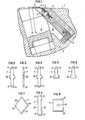
- FIG. 1 shows how in the peripheral recess 10 of the body 2 of the knife shaft 1 the full-cutting knife 3, designed as a one-way turning knife, is pressed against the wear strip 5 by means of knife holder 7 and centrifugal wedge 6.
- the full-cutting knife 3 itself holds one of the further knives 4 arranged in recesses in the knife holder 7, which can be, for example, a scraper, a chip-limiting knife or a knife with another function, in these recesses in the knife holder on the side facing the full-cutting knife 3 Location.
- the effective cutting edges of the other knives lie on a flight circle whose radius R1 is larger than that R 2 of the flight circle of the full-cutting knife.
- an intermediate layer element 11 can be arranged between the full-cutting knife 3 and another knife 4.
- the arrow shows the direction of rotation of the knife shaft 1. With 8 the holding piece for the knife holder 7, 13 with the wooden support elements.
- FIGS. 2 and 3 show an embodiment of one of the further knives 4 with a holding part 20 projecting on both sides in the manner of a cross-beam and cutting edges 22 delimited on both sides with oblique flanks 21 from the front and from the side.
- This further knife is designed as a biaxially symmetrical reversible knife.
- the recesses in the knife holder for receiving these knives have a corresponding cross-like shape.
- FIG. 4 shows a further knife 4, likewise designed as a reversible knife, with a cross-beam-like holding part 20, which, however, has cutters 22 limited by flanks 21 which are inclined at an uneven angle to the cutting edge.
- FIG. 5 shows a holding part 20 projecting approximately on both sides with a T-bar shape
- FIG. 6 shows a further knife 4 equipped with a holding part 20 projecting approximately semicircularly on both sides, each with a symmetrically flanked cutting edge 22.
- the further knife 4 according to FIG. 9, which is equipped with a full cutting edge over the entire width, has a holding part 20 formed by a circular opening in the center of its body.
- This opening can also have any other, at least centrically symmetrical shape and cooperate with a corresponding bolt in the recess in the knife holder.
- the knife holder 7 shown in FIG. 10 for an oblique-cut knife shaft has recesses 12 on its surface facing the full-knife, the shape of which corresponds to the shape of the further knives described.
- additional knives as shown in FIGS. 2 to 4, are used.
- the knife holder 7 applies protrusion rising from right to left over the top of the knife holder 7
- Pointing, nose-like wooden support elements 13, the upper limit of which corresponds to the contour of the knife shaft body, and the recesses 12 for receiving the further knives are worked into the knife holder 7 at the points where these support elements 13 are arranged. 10 that the cross-like recesses 12 for the further knives are arranged to rise from right to left against the top of the knife holder 7 by approximately 1 mm, so that the same knives lie on a flight circle.
- FIG. 11 and 12 show details of the knife holder 7 shown in FIG. 10 on the basis of the sectional views along the sectional planes XI-XI and XII-XII.
- the knife shaft shown only partially in Fig. 1 has a plurality, z. B. 12, peripheral recesses. If the board of the other knives is now twice the chip thickness compared to the full-cutting knife, then the other knives can be dispensed with in the two recesses downstream of this recess as seen in the direction of rotation. If the board of the other knives is three or four times, more recesses can be provided without additional knives. However, there is also the possibility that, for example, a knife holder is used in the first recess, which has only the recesses labeled a). In the subsequent peripheral recess of the knife shaft, a knife holder is then provided which has only the recesses b ).
Landscapes
- Engineering & Computer Science (AREA)
- Life Sciences & Earth Sciences (AREA)
- Manufacturing & Machinery (AREA)
- Mechanical Engineering (AREA)
- Wood Science & Technology (AREA)
- Forests & Forestry (AREA)
- Manufacture Of Wood Veneers (AREA)
- Debarking, Splitting, And Disintegration Of Timber (AREA)
Abstract
Description
Die vorliegende Erfindung betrifft eine Messerwelle zur Herstellung von flächigen Holzspänen mit vorbestimmter Länge und Stärke.The present invention relates to a knife shaft for producing flat wood chips with a predetermined length and thickness.
Derartige Messerwellen sind in verschiedenen Ausführungsformen bekannt und in Gebrauch.Knife shafts of this type are known in various embodiments and are in use.
Sie weisen üblicherweise einen im wesentlichen rotationssymmetrischen Messerwellenkörper auf, in dessen periphere, parallel oder schräg zur Achse gerichtete Ausnehmungen längliche Messer, deren Schneiden in der gewünschten Spanstärke entsprechendem Ausmaß über die Oberfläche des Messerwellenkörpers hinausragen und verschiedene Ausbildungsformen aufweisen können, mittels Messerhalter(n) und Fliehkeil(en) in Lage gehalten sind.They usually have an essentially rotationally symmetrical knife shaft body, in the peripheral recesses of which, parallel or obliquely to the axis, elongated knives, the cutting edges of which, in the desired chip thickness, protrude correspondingly beyond the surface of the knife shaft body and can have various designs, by means of knife holders (s) and Centrifugal wedge (s) are held in place.
Zur Herstellung von Spänen mit vorbestimmter Länge sind verschiedene Messer-Bauarten bekannt. So sind beispielsweise Doppelkamm-Messer in Gebrauch, bei denen die Schneide in abwechselnd höherem und weniger hohem Überstand die Oberfläche des Messerwellenkörpers überragende Einzel-Schneiden unterteilt ist. Die SpanlängenBegrenzung erfolgt durch das Brechen der Späne an den zwischen den Einzel-Schneiden angeordneten Schneidenflanken. Derartige Doppelkamm-Messer sind in der Herstellung aufwendig und auch das Nachschleifen erfordert Präzision und relativ aufwendige Einrichtungen.Various types of knives are known for producing chips with a predetermined length. For example, double-comb knives are used in which the cutting edge is subdivided into individual cutting edges which protrude the surface of the knife shaft body in alternately higher and less high overhang. The chip length is limited by breaking the chips on the cutting edge flanks arranged between the individual cutting edges. Such double-comb knives are complex to manufacture and regrinding also requires precision and relatively complex equipment.
Eine relativ einfache Art von Messern für die Herstellung von Spänen vorbestimmter Länge weist eine im wesentlichen durchgehende Schneide auf, in welchen an den Stellen, wo die Begrenzung der Spanlänge erwünscht ist, Schneiden-Vorsprünge eingearbeitet sind, z. B. durch eine Verformung der Schneide oder durch eine Stanzung an diesen Stellen. Solche VorsprUnge können gegebenenfalls auch an das Messer angelötet oder angeschweißt sein. Es sei an dieser Stelle erwähnt, daß im Falle hochlegierter Stähle das Einarbeiten von Spanbegrenzungs-Kanten oder -Vorsprüngen schwierig ist.A relatively simple type of knife for the production of chips of a predetermined length has a substantially continuous cutting edge, in which, at the points where the limitation of the cutting length is desired, cutting edge projections are incorporated, e.g. B. by a deformation of the cutting edge or by a Punched at these points. Such projections can optionally also be soldered or welded to the knife. It should be mentioned at this point that in the case of high-alloy steels it is difficult to incorporate chip-limiting edges or protrusions.
Weiters sind Vollschneiden-Messer bekannt, welchen zur Begrenzung der Spanlänge eigene weitere Messer zugeordnet sind.Furthermore, full-cutting knives are known, to which separate additional knives are assigned to limit the chip length.
Es ist eine Variante solcher Messer bekannt, die durch ein übliches Vollschneiden-Messer mit kontinuierlicher Schneide gebildet ist, wobei in der Brust dieses Messers Nuten bzw. Ausnehmungen vorgesehen sind, in welche die weiteren Messer eingesetzt sind. Mittels des Messerhalters können diese in den Ausnehmungen sitzenden, weiteren Messer zusammen mit dem Vollschneiden-Messer in Lage gehalten werden.A variant of such knives is known, which is formed by a conventional full-cutting knife with a continuous cutting edge, grooves or recesses being provided in the breast of this knife, into which the further knives are inserted. By means of the knife holder, these additional knives sitting in the recesses can be held in position together with the full-cutting knife.
Zu diesen eben erwähnten Messern sei die DE-OS 2 952 710 genannt, welche ein nachschleifbares Messer für eine Holzzerspanungsmaschine, das auf fast der gesamten Länge der Schneidkante schneidet und an der Spanablauffläche vom Messergrund ausgehende, dicht vorgeordnete Ritzer zur Querunterteilung des Spangutes aufweist, die in einer Ebene mit der Freifläche des Messers liegen, betrifft, bei welchem jeder Ritzer als selbständiges Ritzelement in einer Haltenut, die über mindestens einen Teil des Messergrundkörpers verläuft, formschlüssig eingesetzt und in dieser befestigt ist.For these knives just mentioned, DE-OS 2 952 710 may be mentioned, which has a regrindable knife for a wood-cutting machine that cuts almost the entire length of the cutting edge and on the chip run-off surface from the knife base, densely arranged scratches for the transverse division of the chip material lie in a plane with the free surface of the knife, in which each scorer is inserted as an independent scoring element in a retaining groove which extends over at least part of the basic knife body, and is fastened therein.
Die dort beschriebenen Ritzer können in die Ausnehmungen der Messerbrust beispielsweise eingelötet, eingeschweißt, eingeklebt oder eingeklemmt sein. Da die Herstellung der Ausnehmungen in den Vollschneiden-Messer aufwendig ist, kommt auch darum der Gebrauch dieser Messer als Einweg-Messer nicht in Frage.The cutters described there can be soldered, welded, for example, into the recesses of the knife breast, be glued or pinched. Since the production of the recesses in the full-cutting knife is complex, the use of these knives as disposable knives is also out of the question.
Einweg-Messer setzen sich in immer größerem Umfang durch. Sie bleiben bis zu ihrem vollen Verschleiß in Gebrauch und werden danach durch neue Einweg-Messer ersetzt. Bei solchen Messern, die verständlicherweise möglichst kostengünstig herstellbar sein müssen, kann das bisher übliche Nachschleifen und das Einjustieren des geschliffenen Messers in die der gewünschten Spanstärke entsprechende(n) Position(en) unterbleiben.Disposable knives are becoming increasingly popular. They remain in use until they are fully worn and are then replaced by new disposable knives. In the case of such knives, which understandably have to be able to be produced as inexpensively as possible, the hitherto usual regrinding and adjustment of the ground knife into the position (s) corresponding to the desired chip strength can be omitted.
Ein Problem stellt das Faktum dar, daß bei allen Bauarten die weiteren Messer, also z. B. Ritz-Messer oder Spanlängen-Begrenzungsmesser, wesentlich kürzere Standzeiten haben als die eigentlichen Spanschneide-Messer, da sie einer wesentlich höheren Beanspruchung ausgesetzt sind.A problem is the fact that the other knives, ie z. B. scribing knives or chip length limiting knives, have significantly shorter service lives than the actual chip-cutting knives, since they are exposed to a much higher load.
Die vorliegende Erfindung hat es sich zur Aufgabe gestellt, die beschriebenen Probleme zu lösen und eine Messerwelle zu schaffen, bei welcher dem Unterschied im Verschleiß zwischen den weiteren Messern und den eigentlichen Spanschneide-Messern Rechnung getragen werden kann, die aufwendige Herstellung von Ausnehmungen in der Brust des Spanschneide-Messers zur Aufnahme der weiteren Messer vermieden werden kann und sowohl die Spanschneide-Messer als auch die weiteren Messer als Einwegmesser ausgebildet sein können.The present invention has set itself the task of solving the problems described and to create a knife shaft, in which the difference in wear between the other knives and the actual chip-cutting knives can be taken into account, the complex production of recesses in the chest of the chip-cutting knife for receiving the additional knives can be avoided and both the chip-cutting knife and the other knives can be designed as disposable knives.
Gegenstand der Erfindung ist eine Messerwelle, insbesondere Schrägschnitt-Messerwelle, zur Herstellung von flächigen Holzspänen mit vorbestimmter Länge und Stärke, mit peripheren Ausnehmungen zur Aufnahme von Vollschneiden-Messer, Messerhalter, Fliehkeil, gegebenenfalls einer Verschleißleiste u.dgl., wobei die wirksame Schneide des Vollschneiden-Messers auf einem Flugkreis gehalten ist und dem Vollschneiden-Messer eine Mehrzahl weiterer Messer zur Begrenzung der Spanlänge zugeordnet ist, die dadurch gekennzeichnet ist, daß die weiteren Messer als Einweg-Messer ausgebildet und in Ausnehmungen des Messerhalters angeordnet sind und durch das ebenfalls als Einweg-Messer ausgebildete Vollschneiden-Messer in ihrer Lage gehalten sind.The invention relates to a knife shaft, in particular an oblique cut knife shaft, for manufacture of flat wood chips with a predetermined length and thickness, with peripheral recesses for receiving full-blade knives, knife holders, centrifugal wedges, possibly a wear strip and the like, the effective cutting edge of the full-blade knife being held on a flight circle and the full-blade knife one A plurality of further knives is assigned to limit the chip length, which is characterized in that the further knives are designed as disposable knives and are arranged in recesses in the knife holder and are held in their position by the full-cutting knives also designed as disposable knives.
Die erfindungsgemäß vorgesehene Anordnung der weiteren Messer in Ausnehmungen des Halters für das Vollschneiden-Messer ermöglicht es, einfache und kostengünstige Vollschneiden-Messer ohne eigene Ausnehmungen zu verwenden, die infolgedessen durchaus Einweg-Messer sein können.The arrangement according to the invention of the further knives in recesses of the holder for the full-cutting knife makes it possible to use simple and inexpensive full-cutting knives without their own recesses, which can consequently be disposable knives.
Diese üblicherweise höhere Standzeiten erreichenden Einweg-Vollschneiden-Messer können mit den ebenfalls als Einweg-Messer ausgebildeten weiterez Messern, beispielsweise aus zum Vollschneiden-Messer unterschiedlichem Material, die nach entsprechendem Verschleiß leicht austauschbar sind, kombiniert werden. Weiters ist kein eigener Messerhalter für die weiteren Messer erforderlich, wodurch eine besonders einfache Bauart gegeben ist. Durch die Ausnehmungen im Messerhalter für die weiteren Messer wird es ermöglicht, diese besonders einfach auszugestalten.These disposable full-cutting knives, which usually have a longer service life, can be combined with the other knives, which are also designed as disposable knives, for example made of a different material from the full-cutting knife, which can be easily replaced after corresponding wear. Furthermore, no separate knife holder is required for the other knives, which makes for a particularly simple design. The recesses in the knife holder for the other knives make it possible to make them particularly simple.
Bevorzugt ist eine Ausführungsform der erfindungsgemäßen Messerwelle, bei der die wirksame Schneide des Vollschneiden-Messers und die wirksamen Schneiden der weiteren Messer auf, vorzugsweise zwei, verschiedenen Flugkreisen liegend ausgebildet sind.An embodiment of the knife shaft according to the invention is preferred in which the effective cutting edge of the full-cutting knife and the effective cutting edges of the further knives are designed to lie on, preferably two, different flight circles.
Weisen die Schneiden der in die Ausnehmungen des Messerhalters eingesetzten weiteren Messer von einer Seite des Messerhalters zur anderen einen zu- oder abnehmenden Abstand zum Flugkreis der Schneide des Vollschneiden-Messers auf, so kann dadurch ein gleichmäßig tiefes Ritzen des zu zerspanenden Holzes bzw. ein gleichmäßiges Schneiden der Späne erreicht werden, wodurch ein unerwünschter und unkontrollierter Feinanteil vermieden werden kann.If the cutting edges of the additional knives inserted into the recesses of the knife holder have a widening or decreasing distance from one side of the knife holder to the cutting circle of the cutting edge of the full-cutting knife, this can result in a uniformly deep scoring of the wood to be cut or a uniform one Cutting the chips can be achieved, whereby an undesirable and uncontrolled fine fraction can be avoided.
Weisen die Ausnehmungen für die weiteren Messer im Messerhalter von einer Seite des Messerhalters zur anderen einen zu- oder abnehmenden Abstand zum Flugkreis des Vollschneiden-Messers auf, so können weitere Messer von identer Form für jede der Ausnehmungen im Messerhalter verwendet werden, wobei trotzdem ein über die gesamte Breite gleichmäßig tiefes Ritzen des zu zerkleinernden Holzes erreichbar ist.If the recesses for the other knives in the knife holder have an increasing or decreasing distance from one side of the knife holder to the flight circle of the full-cutting knife, additional knives of identical shape can be used for each of the recesses in the knife holder, although an over the entire width of evenly deep scribing of the wood to be shredded can be reached.
Ist beispielsweise, wie dies gemäß einer vorteilhaften Ausführungsform der Erfindung vorgesehen ist, der Radius des Flugkreises der weiteren Messer größer als der Flugkreisradius der Schneide des Vollschneiden-Messers, so können je nach Vorstand der weiteren Messer in den folgenden Ausnehmungen der Messerwelle lediglich Vollschneiden-Messer angeordnet sein, da ein Vorschneiden für die Spanlänge bereits erfolgt ist.If, for example, as is provided in accordance with an advantageous embodiment of the invention, the radius of the flight circle of the further knives is greater than the flight circle radius of the cutting edge of the full-cutting knife, then depending on the board of the further knives in the following recesses of the knife shaft, only full-cutting knives can be arranged since a pre-cutting for the chip length has already been carried out.
Wenn die Schneiden der weiteren Messer die Schneide des Vollschneiden-Messers um zumindest die doppelte Spanstärke überragt, so kann einem Vollschneiden-Messer mit weiteren Messer zumindest ein bis zwei Vollschneiden-Messer ohne weiteren Messer nachgeordnet werden. Dadurch ergibt sich ein geringerer Arbeitsaufwand beim Auswechseln der weiteren Messer, weiters besteht die Möglichkeit, daß auch Messerhalter ohne Ausnehmungen für die weiteren Messer verwendet werden können.If the cutting edges of the further knives protrude the cutting edge of the full-cutting knife by at least twice the chip thickness, then a full-cutting knife with additional knives can be followed by at least one or two full-cutting knives without an additional knife. This results in less work when replacing the other knives, and there is also the possibility that knife holders without recesses can be used for the other knives.
Gemäß einer weiteren Variante kann auch vorgesehen sein, daß in einer jeweils betrachteten peripheren Ausnehmung der Messerwelle nur ein Teil, beispielsweise jede zweite, der Ausnehmungen im Messerhalter, mit jeweils einem der weiteren Messer gefüllt ist und daß in der darauffolgenden, peripheren Ausnehmung jeweils in der Position, beispielsweise um eine Position, verschoben, ebenfalls ein Teil, beispielsweise jede zweite, der Ausnehmungen im Messerhalter jeweils mit einem weiteren Messer besetzt ist und so fort.According to a further variant, provision can also be made for only a part, for example every second one, of the recesses in the knife holder to be filled with one of the further knives in a respective peripheral recess of the knife shaft, and that in the subsequent peripheral recess in each case in the Position, for example shifted by one position, also a part, for example every second, the recesses in the knife holder are each occupied by a further knife and so on.
Dadurch kann erreicht werden, daß pro Zeiteinheit weniger weitere Messer, die die Spanlängenbegrenzung durchführen, mit dem zu zerkleinernden Holz kooperieren, wobei jedoch die weiteren Messer tiefer in das Holz eingreifen, sodaß breitere Späne entstehen, wodurch erneut eine Steuerung des Feinanteiles im Spangut erzielt werden kann.This means that fewer additional knives, which carry out the chip length limitation, cooperate with the wood to be shredded per unit of time, whereby however the further knives reach deeper into the wood, so that wider chips are produced, which again controls the fine fraction in the chip material can.
Weisen die weiteren Messer einen Halteteil auf, so ist der Sitz dieser im Messerhalter nicht nur durch Klemmwirkung sondern auch durch eine mechanische Verankerung möglich.If the other knives have a holding part, they can be seated in the knife holder not only by clamping action but also by mechanical anchoring.
Einebesonders einfach zu fertigende Ausführungsform der weiteren Messer besteht darin, daß der Halteteil die Form mindestens eines Vorsprunges und/oder mindestens einer Ausnehmung in mindestens einer der seitlichen Flanken des Körpers der weiteren Messer aufweist.A particularly simple embodiment of the further knives is that the holding part has the shape of at least one projection and / or at least one recess in at least one of the side flanks of the body of the further knives.
Schließen die, die Schneide der weiteren Messer beidseitig begrenzenden Flanken mit der Schneide verschieden große Winkel ein, so kann die zur Spanlängenbegrenzung in das Holz eingearbeitete Nut parallele Wände aufweisen, wodurch erneut eine günstige Beeinflussung des Feinanteils gegeben ist.If the flanks delimiting the cutting edge of the other knives on both sides form different angles with the cutting edge, then the groove machined into the wood to limit the chip length can have parallel walls, which again has a favorable influence on the fine fraction.
Um einen einfachen Einbau und auch gegebenenfalls die materialsparende Variante als Wendemesser vorzusehen, können die Halteteile zweiachsig oder zentrisch symmetrisch ausgebildet sein. Sind die Schneiden der weiteren Messer im wesentlichen parallel zur Schneide des Vollschneiden-Messers ausgerichtet, so können die weiteren Messer besonders einfach gefertigt werden, da es lediglich erforderlich ist, sie aus einem entsprechenden Bandstahl durch Ablängen zu erzeugen, wobei weiters durch die Länge der Schneide der weiteren Messer ein Verhindern des staubförmigen Feinanteils bei den Spänen möglich ist.In order to provide a simple installation and possibly also the material-saving variant as a reversible knife, the holding parts can be designed to be biaxially or centrically symmetrical. If the cutting edges of the other knives are aligned essentially parallel to the cutting edge of the full-cutting knife, then the additional knives can be manufactured in a particularly simple manner, since it is only necessary to produce them from a corresponding steel strip by cutting to length, furthermore by the length of the cutting edge the further knife can prevent the dusty fine fraction in the chips.
Sind die weiteren Messer an den Stellen angeordnet, wo die Holzabstützelemente im Messerhalter vorgesehen sind, so kann ein besonders freier Ablauf der Späne erreicht werden, wodurch eine besonders hohe Funktionssicherheit gewährleistet ist.If the other knives are arranged at the points where the wooden support elements are provided in the knife holder, the chips can be run off particularly freely, which ensures particularly high functional reliability.
Anhand der Zeichnung sei die Erfindung näher erläutert :
- Es zeigen die
- Fig. 1 einen Schnitt durch eine erfindungsgemäße Messerwelle, in deren peripherer Ausnehmung ein Einweg-Vollschneiden-Messer und in deren Messerhalter die weiteren Messer angeordnet sind,
- Fig. 2 bis 9 verschiedene Ausbildungsformen der in den Ausnehmungen des Messerhalters einzusetzenden weiteren Messer,
- Fig. 10 eine Ansicht eines erfindungsgemäß mit Ausnehmungen für die Aufnahme der weiteren Messer versehenen Messerhalters, einer Schrägschnitt-Messerwelle und die
- Fig. 11 und 12 jeweils Schnitte durch den Messerhalter der Fig. 10 entlang der Schnittebene XI-XI und XII-XII.
- They show
- 1 shows a section through a knife shaft according to the invention, in the peripheral recess of which a disposable full-cutting knife and in whose knife holder the further knives are arranged,
- 2 to 9 different forms of training of further knives to be inserted in the recesses of the knife holder,
- Fig. 10 is a view of a knife holder provided according to the invention with recesses for receiving the further knives, an oblique-cut knife shaft and the
- 11 and 12 are sections through the knife holder of FIG. 10 along the section plane XI-XI and XII-XII.
Die Schnittansicht der Fig. 1 zeigt, wie in der peripheren Ausnehmung 10 des Körpers 2 der Messerwelle 1 das als Einwegwendemesser ausgebildete Vollschneiden-Messer 3 mittels Messerhalter 7 und Fliehkeil 6 gegen die Verschleißleiste 5 gepreßt ist. Das Vollschneiden-Messer 3 selbst hält eines der in Ausnehmungen des Messerhalters 7 angeordneten weiteren Messer 4, das z.B. ein Ritzer, ein Spanbegrenzungsmesser oder ein Messer mit anderer Funktion sein kann, in diesen Ausnehmungen im Messerhalter an der dem Vollschneiden-Messer 3 zugekehrten Seite in Lage. Die wirksamen Schneiden der weiteren Messer liegen auf einem Flugkreis, dessen Radius R1 größer ist als jener R2 des Flugkreises des Vollschneiden-Messers. Gegebenenfalls kann zwischen Vollschneiden-Messer 3 und weiterem Messer 4 ein Zwischenlage-Element 11 angeordnet sein. Der Pfeil zeigt die Drehrichtung der Messerwelle 1 an. Mit 8 sind das Haltestück für den Messerhalter 7, mit 13 die Holzabstützungs-Elemente bezeichnet.The sectional view of FIG. 1 shows how in the
Die Fig. 2 und 3 zeigen eine Ausführungsform eines der weiteren Messer 4 mit einem beidseitig kreuzbalkenartig vorspringenden Halteteil 20 und beidseitig mit schrägen Flanken 21 begrenzten Schneiden 22 von vorne und von der Seite. Dieses weitere Messer ist als biaxial symmetrisches Wendemesser ausgebildet. Die Ausnehmungen im Messerhalter zur Aufnahme dieser Messer weisen eine entsprechende kreuzartige Form auf.2 and 3 show an embodiment of one of the
Die Fig. 4 zeigt ein ebenfalls als Wendemesser ausgebildetes, weiteres Messer 4 mit kreuzbalkenartigem Halteteil 20, das allerdings durch in ungleichen Winkel zur Schneide geneigte Flanken 21 begrenzte Schneiden 22 aufweist.4 shows a
Die Fig. 5 zeigt ein mit beidseitig etwa T-balkenförmig vorspringendem Halteteil 20 und die5 shows a
Fig. 6 ein mit einem beidseitig etwa halbkreisförmig vorspringenden Halteteil 20 ausgestattetes weiteres Messer 4 mit jeweils einer symmetrisch flankierten Schneide 22.6 shows a
Bei dem in Fig. 7 gezeigten weiteren Wende-Messer 4 sind relativ zur Schneide des Vollschneiden-Messers stark geneigte Schneiden 22 vorgesehen. Die Halterung dieses Messers wird durch dessen, etwa rhomboide Gestalt gewährleistet.In the further
Beim biaxial symmetrisch gestalteten weiteren Messer 4 gemäß Fig. 8 bilden beidseitige Ausnehmungen den Halteteil 20.In the biaxially symmetrically designed
Das mit einer über die gesamte Breite mit einer vollen Schneide ausgestattete breite, weitere Messer 4 gemäß Fig. 9 weist im Zentrum seines Körpers einen durch eine kreisrunde Öffnung gebildeten Halteteil 20 auf. Diese Öffnung kann auch jede andere, zumindest zentrisch symmetrische Gestalt haben und mit einem entsprechenden Bolzen in der Ausnehmung im Messerhalter kooperieren.The
Der in der Fig. 10 gezeigte Messerhalter 7 für eine Schrägschnitt-Messerwelle trägt an seiner dem Vollschneiden-Messer zugekehrten Fläche Ausnehmungen 12, deren Gestalt der Form der beschriebenen weiteren Messer entspricht. In die in Fig. 10 gezeigten Ausnehmungen 12 können z. B. weitere Messer, wie sie die Fig. 2 bis 4 zeigen, eingesetzt werden. Wie aus der Fig. ersichtlich, trägt der Messerhalter 7 von rechts nach links steigenden Überstand über die Oberseite des Messerhalters 7 aufweisende, nasenartige Holzabstützungs-Elemente 13, deren obere Begrenzung der Kontur des Messerwellenkörpers entspricht, und die Ausnehmungen 12 zur Aufnahme der weiteren Messer sind an den Stellen, wo diese Abstützungs-Elemente 13 angeordnet sind, in den Messerhalter 7 eingearbeitet. Außerdem ist aus der Fig. 10 ersichtlich, daß die kreuzartigen Ausnehmungen 12 für die weiteren Messer von rechts nach links gegen die Oberseite des Messerhalters 7 um etwa 1 mm ansteigend angeordnet sind, wodurch bei gleichen weiteren Messern die Schneiden auf einem Flugkreis liegen.The
Die Fig. 11 und 12 zeigen Details des in Fig. 10 gezeigten Messerhalters 7 anhand der Schnittansichten entlang der dort verzeichneten Schnittebenen XI-XI und XII-XII.11 and 12 show details of the
Die in Fig. 1 nur ausschnittsweise dargestellte Messerwelle weist eine Mehrzahl,z. B. 12,periphere Ausnehmungen auf. Ist nun der Vorstand der weiteren Messer gegenüber dem Vollschneiden-Messer das Doppelte der Spandicke, so kann in den dieser Ausnehmung in Drehrichtung gesehen nachgeordneten zwei Ausnehmungen, auf die weiteren Messer verzichtet werden. Beträgt der Vorstand der weiteren Messer das Drei- oder Vierfache, so können entsprechend mehr Ausnehmungen ohne weitere Messer vorgesehen werden. Es besteht allerdings auch die Möglichkeit, daß beispielsweise in der ersten Ausnehmung ein Messerhalter eingesetzt wird, welcher nur die mit a) bezeichneten Ausnehmungen aufweist. In der darauffolgenden peripheren Ausnehmung der Messerwelle wird sodann ein Messerhalter vorgesehen, welcher nur die Ausnehmungen b) aufweist.The knife shaft shown only partially in Fig. 1 has a plurality, z. B. 12, peripheral recesses. If the board of the other knives is now twice the chip thickness compared to the full-cutting knife, then the other knives can be dispensed with in the two recesses downstream of this recess as seen in the direction of rotation. If the board of the other knives is three or four times, more recesses can be provided without additional knives. However, there is also the possibility that, for example, a knife holder is used in the first recess, which has only the recesses labeled a). In the subsequent peripheral recess of the knife shaft, a knife holder is then provided which has only the recesses b ).
Je nach Vorstand der weiteren Messer können in den nachfolgenden peripheren Ausnehmungen entweder lediglich Vollschneiden-Messer oder auch weitere Messer vorgesehen sein.Depending on the board of the other knives, either only full-cutting knives or also further knives can be provided in the subsequent peripheral recesses.
Claims (15)
Applications Claiming Priority (2)
| Application Number | Priority Date | Filing Date | Title |
|---|---|---|---|
| AT200/82 | 1982-01-21 | ||
| AT20082A AT377225B (en) | 1982-01-21 | 1982-01-21 | KNIFE SHAFT FOR THE PRODUCTION OF FLAT WOOD SHAVINGS |
Publications (2)
| Publication Number | Publication Date |
|---|---|
| EP0085040A2 true EP0085040A2 (en) | 1983-08-03 |
| EP0085040A3 EP0085040A3 (en) | 1986-06-11 |
Family
ID=3484138
Family Applications (1)
| Application Number | Title | Priority Date | Filing Date |
|---|---|---|---|
| EP83890008A Withdrawn EP0085040A3 (en) | 1982-01-21 | 1983-01-21 | Tool spindle for the manufacture of flat wood chips |
Country Status (2)
| Country | Link |
|---|---|
| EP (1) | EP0085040A3 (en) |
| AT (1) | AT377225B (en) |
Cited By (4)
| Publication number | Priority date | Publication date | Assignee | Title |
|---|---|---|---|---|
| EP0125371A1 (en) * | 1983-01-21 | 1984-11-21 | HOMBAK Maschinenfabrik GmbH u. Co KG | Scoring knife for a wood flaking cutter head |
| EP0255546A1 (en) * | 1986-07-28 | 1988-02-10 | Dimetal | Wood-support knife guides for wood chipping machines |
| AT398403B (en) * | 1993-03-23 | 1994-12-27 | Boehler Ybbstalwerke | KNIFE ROLLER AND COMB KNIFE FOR KNIFE SHAFT CUTTER |
| WO2009111234A1 (en) * | 2008-02-29 | 2009-09-11 | Simonds International Corporation | Ring strander knife assembly and method of use |
Families Citing this family (2)
| Publication number | Priority date | Publication date | Assignee | Title |
|---|---|---|---|---|
| DE3437688C1 (en) * | 1984-10-15 | 1986-01-23 | Inter-Wood-Maschinen GmbH & Co KG, 8923 Lechbruck | Knife holder for the knife head of a wood cutting machine |
| AT514422B1 (en) * | 2013-11-05 | 2015-01-15 | Böhler Profil Gmbh | Method for producing cutting blades |
Citations (7)
| Publication number | Priority date | Publication date | Assignee | Title |
|---|---|---|---|---|
| GB959240A (en) * | 1962-05-21 | 1964-05-27 | Evert Victor Bloomquist | Pulverizing machine |
| GB1195085A (en) * | 1966-09-22 | 1970-06-17 | Alfred Kohler | Improvements in or relating to a Cutting Tool. |
| DE2241938A1 (en) * | 1972-08-25 | 1974-03-14 | Hombak Maschinenfab Kg | CUTTER SHAFT FOR WOOD CHIPPING MACHINES |
| DE2345961A1 (en) * | 1973-09-12 | 1975-03-20 | Buerener Maschf Gmbh | Wood chipper blade shaft - has two blades offset on common holder, for comb and/or stripper blades |
| FR2332108A1 (en) * | 1975-11-21 | 1977-06-17 | Pessa Oleodinamica | Wood comminution and chip production system - has roller with inbuilt knives and section breaker elements |
| FR2358249A1 (en) * | 1976-07-16 | 1978-02-10 | Ver Edelstahlwerke Ag | Disposable blade assembly for wood shaving device - has same shape as conventional resharpenable blades to allow b conversion |
| DE2915268A1 (en) * | 1979-04-14 | 1980-10-23 | Hombak Maschf Gmbh | Flat wood chip cutting rotating shaft blade - has combing and continuous strip blades with edges enclosing acute angle |
-
1982
- 1982-01-21 AT AT20082A patent/AT377225B/en not_active IP Right Cessation
-
1983
- 1983-01-21 EP EP83890008A patent/EP0085040A3/en not_active Withdrawn
Patent Citations (7)
| Publication number | Priority date | Publication date | Assignee | Title |
|---|---|---|---|---|
| GB959240A (en) * | 1962-05-21 | 1964-05-27 | Evert Victor Bloomquist | Pulverizing machine |
| GB1195085A (en) * | 1966-09-22 | 1970-06-17 | Alfred Kohler | Improvements in or relating to a Cutting Tool. |
| DE2241938A1 (en) * | 1972-08-25 | 1974-03-14 | Hombak Maschinenfab Kg | CUTTER SHAFT FOR WOOD CHIPPING MACHINES |
| DE2345961A1 (en) * | 1973-09-12 | 1975-03-20 | Buerener Maschf Gmbh | Wood chipper blade shaft - has two blades offset on common holder, for comb and/or stripper blades |
| FR2332108A1 (en) * | 1975-11-21 | 1977-06-17 | Pessa Oleodinamica | Wood comminution and chip production system - has roller with inbuilt knives and section breaker elements |
| FR2358249A1 (en) * | 1976-07-16 | 1978-02-10 | Ver Edelstahlwerke Ag | Disposable blade assembly for wood shaving device - has same shape as conventional resharpenable blades to allow b conversion |
| DE2915268A1 (en) * | 1979-04-14 | 1980-10-23 | Hombak Maschf Gmbh | Flat wood chip cutting rotating shaft blade - has combing and continuous strip blades with edges enclosing acute angle |
Cited By (6)
| Publication number | Priority date | Publication date | Assignee | Title |
|---|---|---|---|---|
| EP0125371A1 (en) * | 1983-01-21 | 1984-11-21 | HOMBAK Maschinenfabrik GmbH u. Co KG | Scoring knife for a wood flaking cutter head |
| EP0255546A1 (en) * | 1986-07-28 | 1988-02-10 | Dimetal | Wood-support knife guides for wood chipping machines |
| AT398403B (en) * | 1993-03-23 | 1994-12-27 | Boehler Ybbstalwerke | KNIFE ROLLER AND COMB KNIFE FOR KNIFE SHAFT CUTTER |
| US5456300A (en) * | 1993-03-23 | 1995-10-10 | Bohler Ybbstalwerke G.M.B.H. | Cutter block and knife for a cutter spindle chipper |
| WO2009111234A1 (en) * | 2008-02-29 | 2009-09-11 | Simonds International Corporation | Ring strander knife assembly and method of use |
| US7938155B2 (en) | 2008-02-29 | 2011-05-10 | Simonds International Corporation | Ring strander knife assembly and method of use |
Also Published As
| Publication number | Publication date |
|---|---|
| EP0085040A3 (en) | 1986-06-11 |
| AT377225B (en) | 1985-02-25 |
| ATA20082A (en) | 1984-07-15 |
Similar Documents
| Publication | Publication Date | Title |
|---|---|---|
| DE69111688T2 (en) | Cutting insert for a milling cutter. | |
| DE60210835T2 (en) | cutting insert | |
| EP1087853B1 (en) | Cutting bit, cutting tool and method for machining, especially rotationally symmetrical work piece surfaces | |
| DE3307170A1 (en) | SAW BLADE | |
| DE3611063A1 (en) | SAW BLADE | |
| DE69410271T2 (en) | KNIFE SYSTEM FOR WOOD CUTTING MACHINES, KNIVES, GUIDE ELEMENT AND FILLING ELEMENT, AND METHOD FOR CHANGING KNIVES | |
| DE3211766A1 (en) | SLOT CUTTER | |
| DE2326748A1 (en) | CUTTING TOOL WITH REPLACEABLE CUTTING INSERT | |
| DE2848554C2 (en) | Punching tool | |
| DE3311467C2 (en) | ||
| DE1602795C3 (en) | Cutting body and associated holder | |
| DE3204693A1 (en) | Cutting-off tool | |
| EP0085040A2 (en) | Tool spindle for the manufacture of flat wood chips | |
| DE3819415A1 (en) | Cutting-off tip | |
| EP3741483A1 (en) | Cutting insert, holder and cutting device | |
| DE29607927U1 (en) | Cutting element | |
| DE2455092A1 (en) | CUTTING TOOL | |
| DE2444448A1 (en) | PROCEDURE FOR SAWING A WORKPIECE AND SAW BLADE FOR CARRYING OUT THE PROCESS | |
| DE1146330B (en) | Face cutter head for gear cutting machines | |
| DE3909019C2 (en) | ||
| DE2650293C2 (en) | ||
| DE29710365U1 (en) | Cutting device for extruded molded articles | |
| DE1752498A1 (en) | Milling cutter | |
| DE4243024C2 (en) | Cutting tool | |
| DE2037241B2 (en) | CUTTER |
Legal Events
| Date | Code | Title | Description |
|---|---|---|---|
| PUAI | Public reference made under article 153(3) epc to a published international application that has entered the european phase |
Free format text: ORIGINAL CODE: 0009012 |
|
| AK | Designated contracting states |
Designated state(s): DE FR IT SE |
|
| 17P | Request for examination filed |
Effective date: 19840109 |
|
| PUAL | Search report despatched |
Free format text: ORIGINAL CODE: 0009013 |
|
| AK | Designated contracting states |
Kind code of ref document: A3 Designated state(s): DE FR IT SE |
|
| 17Q | First examination report despatched |
Effective date: 19870720 |
|
| STAA | Information on the status of an ep patent application or granted ep patent |
Free format text: STATUS: THE APPLICATION HAS BEEN WITHDRAWN |
|
| 18W | Application withdrawn |
Withdrawal date: 19880204 |
|
| RIN1 | Information on inventor provided before grant (corrected) |
Inventor name: BERGER, FRIEDRICH Inventor name: SCHUERER, PETER Inventor name: MARCHARD, GUSTAV |