EP0084875A2 - Lineare Anodenstruktur - Google Patents
Lineare Anodenstruktur Download PDFInfo
- Publication number
- EP0084875A2 EP0084875A2 EP83100544A EP83100544A EP0084875A2 EP 0084875 A2 EP0084875 A2 EP 0084875A2 EP 83100544 A EP83100544 A EP 83100544A EP 83100544 A EP83100544 A EP 83100544A EP 0084875 A2 EP0084875 A2 EP 0084875A2
- Authority
- EP
- European Patent Office
- Prior art keywords
- anode
- cable
- sleeve
- porous
- power supply
- Prior art date
- Legal status (The legal status is an assumption and is not a legal conclusion. Google has not performed a legal analysis and makes no representation as to the accuracy of the status listed.)
- Granted
Links
- 229910052751 metal Inorganic materials 0.000 claims abstract description 18
- 239000002184 metal Substances 0.000 claims abstract description 18
- 239000010936 titanium Substances 0.000 claims description 16
- 229910052719 titanium Inorganic materials 0.000 claims description 15
- RTAQQCXQSZGOHL-UHFFFAOYSA-N Titanium Chemical compound [Ti] RTAQQCXQSZGOHL-UHFFFAOYSA-N 0.000 claims description 13
- 239000000463 material Substances 0.000 claims description 5
- 238000007789 sealing Methods 0.000 claims description 2
- 238000004210 cathodic protection Methods 0.000 abstract description 7
- 239000007789 gas Substances 0.000 description 8
- 238000005260 corrosion Methods 0.000 description 7
- 230000007797 corrosion Effects 0.000 description 7
- 239000002689 soil Substances 0.000 description 6
- 210000005069 ears Anatomy 0.000 description 5
- 229910052707 ruthenium Inorganic materials 0.000 description 4
- 239000007787 solid Substances 0.000 description 4
- RYGMFSIKBFXOCR-UHFFFAOYSA-N Copper Chemical compound [Cu] RYGMFSIKBFXOCR-UHFFFAOYSA-N 0.000 description 3
- 229910052802 copper Inorganic materials 0.000 description 3
- 239000010949 copper Substances 0.000 description 3
- 239000004033 plastic Substances 0.000 description 3
- 229920003023 plastic Polymers 0.000 description 3
- KJTLSVCANCCWHF-UHFFFAOYSA-N Ruthenium Chemical compound [Ru] KJTLSVCANCCWHF-UHFFFAOYSA-N 0.000 description 2
- 229910000831 Steel Inorganic materials 0.000 description 2
- 150000001450 anions Chemical class 0.000 description 2
- 239000010405 anode material Substances 0.000 description 2
- QVGXLLKOCUKJST-UHFFFAOYSA-N atomic oxygen Chemical compound [O] QVGXLLKOCUKJST-UHFFFAOYSA-N 0.000 description 2
- 239000011248 coating agent Substances 0.000 description 2
- 238000000576 coating method Methods 0.000 description 2
- 230000005684 electric field Effects 0.000 description 2
- 229910044991 metal oxide Inorganic materials 0.000 description 2
- 150000004706 metal oxides Chemical class 0.000 description 2
- 238000000034 method Methods 0.000 description 2
- 230000003647 oxidation Effects 0.000 description 2
- 238000007254 oxidation reaction Methods 0.000 description 2
- 239000001301 oxygen Substances 0.000 description 2
- 229910052760 oxygen Inorganic materials 0.000 description 2
- BASFCYQUMIYNBI-UHFFFAOYSA-N platinum Chemical group [Pt] BASFCYQUMIYNBI-UHFFFAOYSA-N 0.000 description 2
- -1 polyethylene Polymers 0.000 description 2
- 239000010959 steel Substances 0.000 description 2
- 229920003051 synthetic elastomer Polymers 0.000 description 2
- XLYOFNOQVPJJNP-UHFFFAOYSA-N water Substances O XLYOFNOQVPJJNP-UHFFFAOYSA-N 0.000 description 2
- OKTJSMMVPCPJKN-UHFFFAOYSA-N Carbon Chemical compound [C] OKTJSMMVPCPJKN-UHFFFAOYSA-N 0.000 description 1
- 229910000975 Carbon steel Inorganic materials 0.000 description 1
- VEXZGXHMUGYJMC-UHFFFAOYSA-M Chloride anion Chemical compound [Cl-] VEXZGXHMUGYJMC-UHFFFAOYSA-M 0.000 description 1
- KZBUYRJDOAKODT-UHFFFAOYSA-N Chlorine Chemical compound ClCl KZBUYRJDOAKODT-UHFFFAOYSA-N 0.000 description 1
- MYMOFIZGZYHOMD-UHFFFAOYSA-N Dioxygen Chemical compound O=O MYMOFIZGZYHOMD-UHFFFAOYSA-N 0.000 description 1
- 244000043261 Hevea brasiliensis Species 0.000 description 1
- 239000004698 Polyethylene Substances 0.000 description 1
- 229910000676 Si alloy Inorganic materials 0.000 description 1
- 229910045601 alloy Inorganic materials 0.000 description 1
- 239000000956 alloy Substances 0.000 description 1
- 229910052782 aluminium Inorganic materials 0.000 description 1
- XAGFODPZIPBFFR-UHFFFAOYSA-N aluminium Chemical compound [Al] XAGFODPZIPBFFR-UHFFFAOYSA-N 0.000 description 1
- 238000004873 anchoring Methods 0.000 description 1
- 239000000440 bentonite Substances 0.000 description 1
- 229910000278 bentonite Inorganic materials 0.000 description 1
- SVPXDRXYRYOSEX-UHFFFAOYSA-N bentoquatam Chemical compound O.O=[Si]=O.O=[Al]O[Al]=O SVPXDRXYRYOSEX-UHFFFAOYSA-N 0.000 description 1
- 239000010962 carbon steel Substances 0.000 description 1
- 230000015556 catabolic process Effects 0.000 description 1
- 239000003795 chemical substances by application Substances 0.000 description 1
- 230000000052 comparative effect Effects 0.000 description 1
- 229920001577 copolymer Polymers 0.000 description 1
- 229910001882 dioxygen Inorganic materials 0.000 description 1
- 238000005553 drilling Methods 0.000 description 1
- 229920001971 elastomer Polymers 0.000 description 1
- 239000013536 elastomeric material Substances 0.000 description 1
- 238000005868 electrolysis reaction Methods 0.000 description 1
- 239000013505 freshwater Substances 0.000 description 1
- 239000010439 graphite Substances 0.000 description 1
- 229910002804 graphite Inorganic materials 0.000 description 1
- 238000003780 insertion Methods 0.000 description 1
- 230000037431 insertion Effects 0.000 description 1
- 238000009434 installation Methods 0.000 description 1
- XWHPIFXRKKHEKR-UHFFFAOYSA-N iron silicon Chemical compound [Si].[Fe] XWHPIFXRKKHEKR-UHFFFAOYSA-N 0.000 description 1
- 238000002955 isolation Methods 0.000 description 1
- 230000007774 longterm Effects 0.000 description 1
- 238000012423 maintenance Methods 0.000 description 1
- 150000002739 metals Chemical class 0.000 description 1
- 229920003052 natural elastomer Polymers 0.000 description 1
- 229920001194 natural rubber Polymers 0.000 description 1
- 239000012466 permeate Substances 0.000 description 1
- 230000010287 polarization Effects 0.000 description 1
- 229920000573 polyethylene Polymers 0.000 description 1
- 229920000915 polyvinyl chloride Polymers 0.000 description 1
- 239000004800 polyvinyl chloride Substances 0.000 description 1
- QQONPFPTGQHPMA-UHFFFAOYSA-N propylene Natural products CC=C QQONPFPTGQHPMA-UHFFFAOYSA-N 0.000 description 1
- 230000001681 protective effect Effects 0.000 description 1
- 239000005060 rubber Substances 0.000 description 1
- 239000013535 sea water Substances 0.000 description 1
- 238000000926 separation method Methods 0.000 description 1
- 229910052566 spinel group Inorganic materials 0.000 description 1
- 238000006467 substitution reaction Methods 0.000 description 1
- 239000005061 synthetic rubber Substances 0.000 description 1
- 229910052715 tantalum Inorganic materials 0.000 description 1
- GUVRBAGPIYLISA-UHFFFAOYSA-N tantalum atom Chemical compound [Ta] GUVRBAGPIYLISA-UHFFFAOYSA-N 0.000 description 1
- 125000000391 vinyl group Chemical group [H]C([*])=C([H])[H] 0.000 description 1
- 229920002554 vinyl polymer Polymers 0.000 description 1
Images

Classifications
-
- C—CHEMISTRY; METALLURGY
- C23—COATING METALLIC MATERIAL; COATING MATERIAL WITH METALLIC MATERIAL; CHEMICAL SURFACE TREATMENT; DIFFUSION TREATMENT OF METALLIC MATERIAL; COATING BY VACUUM EVAPORATION, BY SPUTTERING, BY ION IMPLANTATION OR BY CHEMICAL VAPOUR DEPOSITION, IN GENERAL; INHIBITING CORROSION OF METALLIC MATERIAL OR INCRUSTATION IN GENERAL
- C23F—NON-MECHANICAL REMOVAL OF METALLIC MATERIAL FROM SURFACE; INHIBITING CORROSION OF METALLIC MATERIAL OR INCRUSTATION IN GENERAL; MULTI-STEP PROCESSES FOR SURFACE TREATMENT OF METALLIC MATERIAL INVOLVING AT LEAST ONE PROCESS PROVIDED FOR IN CLASS C23 AND AT LEAST ONE PROCESS COVERED BY SUBCLASS C21D OR C22F OR CLASS C25
- C23F13/00—Inhibiting corrosion of metals by anodic or cathodic protection
- C23F13/02—Inhibiting corrosion of metals by anodic or cathodic protection cathodic; Selection of conditions, parameters or procedures for cathodic protection, e.g. of electrical conditions
-
- Y—GENERAL TAGGING OF NEW TECHNOLOGICAL DEVELOPMENTS; GENERAL TAGGING OF CROSS-SECTIONAL TECHNOLOGIES SPANNING OVER SEVERAL SECTIONS OF THE IPC; TECHNICAL SUBJECTS COVERED BY FORMER USPC CROSS-REFERENCE ART COLLECTIONS [XRACs] AND DIGESTS
- Y10—TECHNICAL SUBJECTS COVERED BY FORMER USPC
- Y10T—TECHNICAL SUBJECTS COVERED BY FORMER US CLASSIFICATION
- Y10T29/00—Metal working
- Y10T29/49—Method of mechanical manufacture
- Y10T29/49002—Electrical device making
- Y10T29/49117—Conductor or circuit manufacturing
- Y10T29/49169—Assembling electrical component directly to terminal or elongated conductor
-
- Y—GENERAL TAGGING OF NEW TECHNOLOGICAL DEVELOPMENTS; GENERAL TAGGING OF CROSS-SECTIONAL TECHNOLOGIES SPANNING OVER SEVERAL SECTIONS OF THE IPC; TECHNICAL SUBJECTS COVERED BY FORMER USPC CROSS-REFERENCE ART COLLECTIONS [XRACs] AND DIGESTS
- Y10—TECHNICAL SUBJECTS COVERED BY FORMER USPC
- Y10T—TECHNICAL SUBJECTS COVERED BY FORMER US CLASSIFICATION
- Y10T29/00—Metal working
- Y10T29/49—Method of mechanical manufacture
- Y10T29/49002—Electrical device making
- Y10T29/49117—Conductor or circuit manufacturing
- Y10T29/49174—Assembling terminal to elongated conductor
- Y10T29/49181—Assembling terminal to elongated conductor by deforming
- Y10T29/49185—Assembling terminal to elongated conductor by deforming of terminal
- Y10T29/49192—Assembling terminal to elongated conductor by deforming of terminal with insulation removal
-
- Y—GENERAL TAGGING OF NEW TECHNOLOGICAL DEVELOPMENTS; GENERAL TAGGING OF CROSS-SECTIONAL TECHNOLOGIES SPANNING OVER SEVERAL SECTIONS OF THE IPC; TECHNICAL SUBJECTS COVERED BY FORMER USPC CROSS-REFERENCE ART COLLECTIONS [XRACs] AND DIGESTS
- Y10—TECHNICAL SUBJECTS COVERED BY FORMER USPC
- Y10T—TECHNICAL SUBJECTS COVERED BY FORMER US CLASSIFICATION
- Y10T29/00—Metal working
- Y10T29/49—Method of mechanical manufacture
- Y10T29/49002—Electrical device making
- Y10T29/49117—Conductor or circuit manufacturing
- Y10T29/49194—Assembling elongated conductors, e.g., splicing, etc.
- Y10T29/49195—Assembling elongated conductors, e.g., splicing, etc. with end-to-end orienting
- Y10T29/49199—Assembling elongated conductors, e.g., splicing, etc. with end-to-end orienting including deforming of joining bridge
Definitions
- the present invention pertains to an anodic structure of linear type, electrically connected to a continuous current supply source, which may be advantageously utilized in the field of cathodic protection by the impressed current system.
- Cathodic protection as a system for corrosion control of metal structures operating in natural environments, such as sea water, fresh water or ground, is broadly known and utilized. It works on the principle of electrochemically reducing the oxygen diffused at the boundary contact area with the surface to be protected. Corrosion of the metal is therefore prevented as the oxidating agents.contained in the environment are thus neutralized.
- Cathodic protection can be applied by using sacrificial anodes or alternatively by the impressed current method.
- the structure to be protected is cathodically polarized by suitable connection to the negative pole of an electric current source and the anode, preferably made of a dimensionally stable material, resistant to corrosion, is connected to the positive pole of the same current source.
- the resulting current circulation causes oxygen reduction at the cathode and oxidation of the anions at the anode. Due to the high voltages afforded, in the order of 30 to 40 V, the anodes may be placed at a great distance from the structure surface. The number of polarization anodes required is therefore considerably reduced.
- An attendant requirement to be met is to ensure the best uniformity of current distribution over the structure to be protected by appropriately conforming the electric field to the geometrical characteristics of the structure, varying accordingly the number of anodes, their geometrical form and spatial position relative to the structure to be protected.
- Anodic structures which have to be used in natural environments, often characterized by severe temperature conditions, mechanical stress, corrosion and so on, must ensure a high mechanical resistance and good electrical conductivity in order to afford a long time of operation without any maintenance or substitutions.
- This gas is generally molecular oxygen, which is formed by the oxidation of anions at the anode, but it may be also molecular chlorine, which is easily formed by electrolysis of water containing relatively low chloride concentrations.
- the cathodic protection system This inevitably affects the effectiveness of the cathodic protection system, especially in.deep wells systems wherein the anodes are inserted in vertical wells extending into the ground for considerable length and disposed at intervals of considerable length beside the structure, as for example a grounded pipeline.
- the anodes consist of elongated vertical structures reaching remarkable depths, in the order of various tenths of meters, which hinders gas escape from the vertical surface of the anode segments.
- the gas evolved tends to rise through the ground along the surface of the overhanging anode segment or anyhow to permeate the soil, further reducing the electrical conductivity.
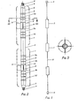
- the anodic structure of the present invention is constituted by an insulated power supply cable, provided with a suitable terminal, at least at one end, for connection to the positive pole of the electric current source and a series of anodic elements made of valve metal comprising porous and permeable elements, distributed over the length of the power supply cable, coaxial with the cable itself and electrically connected through a leak-proof connection with the conductive core without interrupting the continuity of the core.
- the anode structure of the invention as schematically illustrated in Figure 2, comprises an insulated power supply cable 2, having a conductive core of copper or aluminum stranded wires, covered by an insulating sheet of an elastomeric material, such as synthetic and natural rubbers, polyvinylchloride, polyethylene, fluorinated vinyl polymers etc., capable of withstanding corrosion in the medium of utilization of the anode.
- an elastomeric material such as synthetic and natural rubbers, polyvinylchloride, polyethylene, fluorinated vinyl polymers etc.
- the core may be made by rope stranding with the inner group of stranded wires, made of high tensile steel, or the entire conductive core of the cable may be also made of stranded steel wires.
- the cable 2 is provided with a suitable terminal 6 for its electrical connection to the positive pole of the power source.
- the cable 2 may be terminated with a titanium or plastic cap 7, providing a leak-proof sealing of the corrodible conductive core from contact with the environment.
- the cap may advantageously be provided with a hook or ring for anchoring of the anode end or for sustaining a suitable ballast.
- the insulating cap 7 may be advantageously substituted by a water proof type elctrical plug, which will allow the joining of two or more anodic structures in series to double or triple the length of the anode structure according to needs.
- a number of anode segments 1, which number and relative spatial position are dictated by the particular requirements of the specific use of the anode, are inserted coaxially along the power supply cable.
- the number of anode segments and their relative spatial distribution along the cable 2 may be easily adapted to conform with the necessity of providing a uniform current density over the surface to be protected.
- Substantially the distribution of the anode segments along the cable depends on the desired electrical field to be provided between the anode structure and the surface of the structure to be protected.
- each anode element comprises a main porous and permeable body 1, preferably constituted by expanded sheet or metal mesh welded to one or more ears 8, which are in turn welded to a sleeve 3.
- the anode elements are preferably made of valve metal, such as titanium or tantalum or alloys thereof
- the main porous and permeable body 1 may be cylindrical or otherwise may have any different cross- section, such as square, polygonal, star-shaped and so on, or it may be constituted by strips of metal mesh welded to one or more ears 8.
- the mesh or mesh segments constituting the main porous and permeable body 1 are coated with a layer of electrically conductive and anodically resistant material such as a metal belonging to the platinum group or oxide thereof, or other conducting metal oxides such as spinels, perowskites, delafossites, bronzes, etc.
- a particularly effective coating comprises a thermally deposited layer of mixed oxides of ruthenium and titanium in a metal proportion comprised between 20% Ru and 80% Ti or 60% Ru and 40% Ti.
- Each anode element may be pre-fabricated and then coaxially inserted over the power supply cable 2, or the main body 1 may be welded to ears 8, after sleeve 3 is fixed to the power supply cable.
- the electrical connection between the conductive core of the insulated cable 2 and each anode segment 1, is effected by firstly stripping the plastic insulating sheat 5 over the conductive core 4 of the cable for a certain length in correspondence of the central portion of the sleeve 3.
- the sleeve 3 is then squeezed over the stripped portions 3a and 3b of the power cable 2 and over the adjacent insulated portions 3c and 3d of the insulating sheat to provide for the leak proofing of the electrical connection.
- the squeezing of the metal sleeve 3 is effected by subjecting the sleeve to circumference reduction by a radially acting cold heading tool.
- Protective sheats constituted by segments of heat shrinking plastic tubes, consisting for example of fluorinated ehylene and propylene copolymers, may be slipped over the junction between the sleeve 3 and the cable 2 and heated with a hot air blower to.shrink the sheat over the junction to increase the protection of the junction from the external environment.
- the anode that is the main body 1 of the anode segments, is constituted of an expanded sheet of a valve metal such as titanium, coated by a deposit of conductive and non- passivatable material resistant to anodic conditions, said coating applied over all surfaces.
- the anodes of the present invention offer several advantages with respect to conventional bar or rod anodes.
- the drilling mud or filling mud easily penetrates the anodic porous and permeable structure, thus ensuring a large contact surface; and moreover the contact surface is three-dimensional as it is constituted by the sum of all the contact areas which are oriented in different spatial planes. Therefore the contact surface between the anode and the surrounding ground results considerably increase and also in case the soil dries up or gas evolution takes place at the anode surface, the contact area remains substantially effective. In fact, the evolved gas finds an easy way to escape across the anode mesh.
- the problems connected with the use of solid bar or rod anodes, wherein the surfaces cannot be penetrated by the medium are efficaciously overcome by the anodes of the present invention.
- Comparative cathodic protection tests carried out in industrial installations have surprisingly proved that by substituting solid anodes with porous anodes which may be penetrated by the soil, with the same external dimensions, the contact resistance is reduced of about 15% at the start-up and after three months of operation the reduction of the contact resistance compared with the reference solid cylincrical anodes, is up to about 25-30%.
- the anode segments were made using a cylinder of expanded titanium sheet having a thickness of 1.5 mm, with external diameter of 50 mm and were 1500 mm long.
- the cylinder of expanded sheet was coated by a deposit of mixed oxides of ruthenium and titanium in a ratio of 1 : 1 referred to the metals.
- the expanded sheet cylinders were welded to titanium ears, said ears being welded to a titanium pipe having an internal diameter of 10 mm and inserted on a power supply cable and cold-headed for a certain length over the conducting core of the cable, previously stripped of its insulating sheat, and at the opposite ends directly over the insulating elastomeric sheat of the cable, in order to provide leak proofing of the electrical connection.
- the intervals between one anode segment and the other were constant and about 2 meters long.
- One end of the cable was terminated with a titanium cap cold-headed over the insulated cable to seal the core from the environment.
- the cap was provided with a titanium hook.
- the other end of the cable was terminated with a copper eyelet suitable for connection to the power supply.
- the anode structure was inserted in a well having a diameter of about 12.5 cm and a depth of 40 m, drilled in a ground having an average resistivity of 1000 ⁇ . cm. After insertion, the well was filled with bentonite mud.
- the anode was used to protect about 15 km of a 20" gas pipeline of carbon steel coated with high-density polyethylenic synthetic rubber running at a depth of about 2 m in the soil.
- the measured resistance of the anode structure towards the ground was 0.7 ohms at the start-up and the current delivered by the anode was 8 Amperes with a supply voltage of about 7.5 Volts.
- a reference anodic structure similar to the structure of the present invention but consisting of anodic elements made of solid tubolar titanium cylinders having the same external dimensions of the mesh anodes, coated on the external surface by the same electroconductive material was prepared.
- the measured resistance towards ground was 0.8 ohms and after three months of operation the value detected was ip to 1.4 ohms.
Landscapes
- Chemical & Material Sciences (AREA)
- Engineering & Computer Science (AREA)
- Materials Engineering (AREA)
- Mechanical Engineering (AREA)
- Metallurgy (AREA)
- Organic Chemistry (AREA)
- Prevention Of Electric Corrosion (AREA)
- Carbon And Carbon Compounds (AREA)
- Connections Effected By Soldering, Adhesion, Or Permanent Deformation (AREA)
- Processing Of Terminals (AREA)
- Manufacturing Of Electrical Connectors (AREA)
Priority Applications (1)
| Application Number | Priority Date | Filing Date | Title |
|---|---|---|---|
| AT83100544T ATE23368T1 (de) | 1982-01-21 | 1983-01-21 | Lineare anodenstruktur. |
Applications Claiming Priority (2)
| Application Number | Priority Date | Filing Date | Title |
|---|---|---|---|
| IT19208/82A IT1150124B (it) | 1982-01-21 | 1982-01-21 | Struttura anodica per protezione catodica |
| IT1920882 | 1982-01-21 |
Publications (3)
| Publication Number | Publication Date |
|---|---|
| EP0084875A2 true EP0084875A2 (de) | 1983-08-03 |
| EP0084875A3 EP0084875A3 (en) | 1983-08-10 |
| EP0084875B1 EP0084875B1 (de) | 1986-11-05 |
Family
ID=11155804
Family Applications (1)
| Application Number | Title | Priority Date | Filing Date |
|---|---|---|---|
| EP83100544A Expired EP0084875B1 (de) | 1982-01-21 | 1983-01-21 | Lineare Anodenstruktur |
Country Status (17)
| Country | Link |
|---|---|
| US (2) | US4452683A (de) |
| EP (1) | EP0084875B1 (de) |
| JP (2) | JPS58181876A (de) |
| AR (1) | AR232007A1 (de) |
| AT (1) | ATE23368T1 (de) |
| AU (1) | AU553651B2 (de) |
| BR (1) | BR8300230A (de) |
| CA (1) | CA1215937A (de) |
| DE (1) | DE3367418D1 (de) |
| DK (1) | DK156836C (de) |
| ES (1) | ES8402883A1 (de) |
| IT (1) | IT1150124B (de) |
| MX (1) | MX152676A (de) |
| NO (1) | NO159944C (de) |
| NZ (1) | NZ203058A (de) |
| SU (1) | SU1175361A3 (de) |
| UA (1) | UA5968A1 (de) |
Cited By (3)
| Publication number | Priority date | Publication date | Assignee | Title |
|---|---|---|---|---|
| EP0129886A3 (en) * | 1983-06-23 | 1985-10-23 | Oronzio De Nora S.A. | Method for electrically connecting non corrodible anodes to the corrodible core of a power supply cable, power supply cable and tubular anode connected to said cable |
| EP0170929A3 (en) * | 1984-07-12 | 1986-07-16 | Oronzio De Nora S.A. | Electrode assembly for monitoring of cathodically protected structures |
| DE4224539C1 (de) * | 1992-07-27 | 1993-12-16 | Heraeus Elektrochemie | Anodenstruktur für kathodischen Korrosionsschutz sowie Verfahren zur Herstellung der Anodenstruktur |
Families Citing this family (17)
| Publication number | Priority date | Publication date | Assignee | Title |
|---|---|---|---|---|
| IT1170053B (it) * | 1983-12-23 | 1987-06-03 | Oronzio De Nora Sa | Anodo dispersore preimpaccato con backfill in struttura flessibile per protezione catodica con correnti impresse |
| IT1200414B (it) * | 1985-03-13 | 1989-01-18 | Oronzio De Nora Sa | Dispositivo e metodo relativo per la raccolta di parametri chimcofisici,elettrochimici e meccanici per la progettazione e/o l'esercizio di impianti di protezione catodica |
| US5423961A (en) * | 1985-05-07 | 1995-06-13 | Eltech Systems Corporation | Cathodic protection system for a steel-reinforced concrete structure |
| US5098543A (en) * | 1985-05-07 | 1992-03-24 | Bennett John E | Cathodic protection system for a steel-reinforced concrete structure |
| US5421968A (en) * | 1985-05-07 | 1995-06-06 | Eltech Systems Corporation | Cathodic protection system for a steel-reinforced concrete structure |
| US4708888A (en) * | 1985-05-07 | 1987-11-24 | Eltech Systems Corporation | Coating metal mesh |
| US5451307A (en) * | 1985-05-07 | 1995-09-19 | Eltech Systems Corporation | Expanded metal mesh and anode structure |
| WO1986006759A1 (en) * | 1985-05-07 | 1986-11-20 | Eltech Systems Corporation | Cathodic protection system for a steel-reinforced concrete structure and method of installation |
| IT1206747B (it) * | 1986-03-10 | 1989-05-03 | Oronzio De Nora Sa | Impianto di protezione catodica acorrente impressa di piattaforme petrolifere in mare. |
| FR2613541B1 (fr) * | 1987-04-06 | 1990-04-06 | Labinal | Procede de realisation de cosses en plomb ou objets analogues sur des cables en aluminium |
| US5176807A (en) * | 1989-02-28 | 1993-01-05 | The United States Of America As Represented By The Secretary Of The Army | Expandable coil cathodic protection anode |
| WO1996030561A1 (en) * | 1995-03-24 | 1996-10-03 | Alltrista Corporation | Jacketed sacrificial anode cathodic protection system |
| RU2130511C1 (ru) * | 1997-10-30 | 1999-05-20 | Крыщенко Константин Иванович | Анодный заземлитель |
| JP4530296B2 (ja) | 2008-04-09 | 2010-08-25 | Necアクセステクニカ株式会社 | 角度可変構造 |
| US7998631B2 (en) * | 2009-03-10 | 2011-08-16 | GM Global Technology Operations LLC | Method to reduce/eliminate shunt current corrosion of wet end plate in PEM fuel cells |
| KR20120021626A (ko) * | 2010-08-11 | 2012-03-09 | 삼성에스디아이 주식회사 | 연료전지 모듈 및 그 제조 방법 |
| CN112195473B (zh) * | 2020-09-12 | 2022-07-12 | 青岛赢海防腐防污技术有限公司 | 管道内壁用通电保护装置、施工方法及加工方法 |
Family Cites Families (15)
| Publication number | Priority date | Publication date | Assignee | Title |
|---|---|---|---|---|
| US2876190A (en) * | 1955-04-18 | 1959-03-03 | Union Carbide Corp | Duct anode |
| US2851413A (en) * | 1957-07-02 | 1958-09-09 | Jr Harry W Hosford | Anode assembly for cathodic protection system |
| DE1110983B (de) * | 1958-11-26 | 1961-07-13 | Siemens Ag | Elektrode, insbesondere fuer elektrischen Korrosionsschutz von Metallteilen |
| US3022242A (en) * | 1959-01-23 | 1962-02-20 | Engelhard Ind Inc | Anode for cathodic protection systems |
| FR1256548A (fr) * | 1960-02-05 | 1961-03-24 | Contre La Corrosion Soc Et | Dispositif anodique flexible pour la protection cathodique des structures métalliques |
| US3098027A (en) * | 1960-12-09 | 1963-07-16 | Flower Archibald Thomas | Anode connector |
| NL293184A (de) * | 1962-05-26 | |||
| US3527685A (en) * | 1968-08-26 | 1970-09-08 | Engelhard Min & Chem | Anode for cathodic protection of tubular members |
| US3616418A (en) * | 1969-12-04 | 1971-10-26 | Engelhard Min & Chem | Anode assembly for cathodic protection systems |
| US3981790A (en) * | 1973-06-11 | 1976-09-21 | Diamond Shamrock Corporation | Dimensionally stable anode and method and apparatus for forming the same |
| DE2645414C2 (de) * | 1976-10-08 | 1986-08-28 | Hoechst Ag, 6230 Frankfurt | Titananoden für die elektrolytische Gewinnung von Mangandioxid, sowie ein Verfahren zur Herstellung dieser Anoden |
| GB1568885A (en) * | 1977-05-09 | 1980-06-11 | Imi Marston Ltd | Impressed current corrosion-protection anode |
| JPS5838512B2 (ja) * | 1978-02-21 | 1983-08-23 | 中川防蝕工業株式会社 | 深埋式外部電源電気防食用電極装置 |
| US4170532A (en) * | 1978-04-11 | 1979-10-09 | C. E. Equipment, Inc. | Deep well platinized anode carrier for cathodic protection system |
| US4267029A (en) * | 1980-01-07 | 1981-05-12 | Pennwalt Corporation | Anode for high resistivity cathodic protection systems |
-
1982
- 1982-01-21 IT IT19208/82A patent/IT1150124B/it active
- 1982-12-22 AU AU91782/82A patent/AU553651B2/en not_active Expired
- 1982-12-22 US US06/452,268 patent/US4452683A/en not_active Expired - Lifetime
-
1983
- 1983-01-05 MX MX195815A patent/MX152676A/es unknown
- 1983-01-13 NO NO830098A patent/NO159944C/no not_active IP Right Cessation
- 1983-01-17 SU SU833537162A patent/SU1175361A3/ru active
- 1983-01-17 UA UA3537162A patent/UA5968A1/uk unknown
- 1983-01-18 BR BR8300230A patent/BR8300230A/pt not_active IP Right Cessation
- 1983-01-19 AR AR291899A patent/AR232007A1/es active
- 1983-01-20 DK DK022083A patent/DK156836C/da not_active IP Right Cessation
- 1983-01-20 NZ NZ203058A patent/NZ203058A/en unknown
- 1983-01-20 ES ES519147A patent/ES8402883A1/es not_active Expired
- 1983-01-21 JP JP58008624A patent/JPS58181876A/ja active Granted
- 1983-01-21 AT AT83100544T patent/ATE23368T1/de not_active IP Right Cessation
- 1983-01-21 DE DE8383100544T patent/DE3367418D1/de not_active Expired
- 1983-01-21 CA CA000419948A patent/CA1215937A/en not_active Expired
- 1983-01-21 EP EP83100544A patent/EP0084875B1/de not_active Expired
-
1984
- 1984-01-25 US US06/573,732 patent/US4519886A/en not_active Expired - Lifetime
- 1984-11-12 JP JP59238223A patent/JPS60150573A/ja active Pending
Cited By (4)
| Publication number | Priority date | Publication date | Assignee | Title |
|---|---|---|---|---|
| EP0129886A3 (en) * | 1983-06-23 | 1985-10-23 | Oronzio De Nora S.A. | Method for electrically connecting non corrodible anodes to the corrodible core of a power supply cable, power supply cable and tubular anode connected to said cable |
| EP0170929A3 (en) * | 1984-07-12 | 1986-07-16 | Oronzio De Nora S.A. | Electrode assembly for monitoring of cathodically protected structures |
| DE4224539C1 (de) * | 1992-07-27 | 1993-12-16 | Heraeus Elektrochemie | Anodenstruktur für kathodischen Korrosionsschutz sowie Verfahren zur Herstellung der Anodenstruktur |
| US5384020A (en) * | 1992-07-27 | 1995-01-24 | Heraeus Elektrochemie Gmbh | Anode structure for cathodic protection against corrosion, and method for making the anode structure |
Also Published As
| Publication number | Publication date |
|---|---|
| ES519147A0 (es) | 1984-03-01 |
| EP0084875A3 (en) | 1983-08-10 |
| NZ203058A (en) | 1986-01-24 |
| DK156836B (da) | 1989-10-09 |
| JPS58181876A (ja) | 1983-10-24 |
| IT8219208A0 (it) | 1982-01-21 |
| MX152676A (es) | 1985-10-07 |
| JPS6315994B2 (de) | 1988-04-07 |
| EP0084875B1 (de) | 1986-11-05 |
| ATE23368T1 (de) | 1986-11-15 |
| DK22083A (da) | 1983-07-22 |
| SU1175361A3 (ru) | 1985-08-23 |
| NO830098L (no) | 1983-07-22 |
| JPS60150573A (ja) | 1985-08-08 |
| CA1215937A (en) | 1986-12-30 |
| IT1150124B (it) | 1986-12-10 |
| DE3367418D1 (en) | 1986-12-11 |
| ES8402883A1 (es) | 1984-03-01 |
| DK156836C (da) | 1990-03-05 |
| NO159944C (no) | 1989-02-22 |
| US4452683A (en) | 1984-06-05 |
| AR232007A1 (es) | 1985-04-30 |
| DK22083D0 (da) | 1983-01-20 |
| AU553651B2 (en) | 1986-07-24 |
| US4519886A (en) | 1985-05-28 |
| BR8300230A (pt) | 1983-10-18 |
| NO159944B (no) | 1988-11-14 |
| UA5968A1 (uk) | 1994-12-29 |
| AU9178282A (en) | 1983-07-28 |
Similar Documents
| Publication | Publication Date | Title |
|---|---|---|
| US4519886A (en) | Method of making electrical connection to an anode | |
| US3868313A (en) | Cathodic protection | |
| US3616418A (en) | Anode assembly for cathodic protection systems | |
| CA1236046A (en) | Corrosion protection system comprising electrode with conductive core and conductive polymer layer | |
| US3022242A (en) | Anode for cathodic protection systems | |
| US4990231A (en) | Corrosion protection system | |
| CA2108469C (en) | Method for electric protection of metal object, grounding electrode for effecting this method and composition for the grounding electrode | |
| CA2720002C (en) | Polymeric, non-corrosive cathodic protection anode | |
| US3527685A (en) | Anode for cathodic protection of tubular members | |
| US4880517A (en) | Catalytic polymer electrode for cathodic protection and cathodic protection system comprising same | |
| WO1997014196A1 (en) | Grounding electrode | |
| US5739424A (en) | Galvanic corrosion inhibiting coupling interposed between two dissimilar pipes | |
| WO1997013890A1 (en) | Corrosion protection and electrical grounding | |
| ATE42350T1 (de) | Verfahren zum elektrischen verbinden korrosionsfester anoden mit dem nicht korrosionsfesten kern eines stromversorgungskabels und eine roehrenfoermige anode, verbunden mit diesem kabel. | |
| WO2017151001A1 (ru) | Анодный заземлитель | |
| RU2768063C1 (ru) | Способ катодной защиты подземного объекта | |
| EP0401483B1 (de) | Verfahren zum elektrischen Verbinden nichtkorrodierbarer Anoden mit dem korrodierbaren Kern eines kraftliefernden, mit Standardisoliermaterial isolierten Leistungsversorgungskabels | |
| WO2015183133A1 (ru) | Протяженный электрод анодного заземления | |
| CA1278775C (en) | Catalytic polymer electrode for cathodic protection and cathodic protection system comprising same | |
| SU1033577A1 (ru) | Электрод дл электроосмотического обезвоживани почв | |
| RU1778833C (ru) | Анодный заземлитель | |
| ITRM970176U1 (it) | Perfezionamenti nei sistemi di protezione catodica dei dispositivi anodici | |
| JPH0431028B2 (de) | ||
| JPS6036680A (ja) | 埋設パイプラインの電気防食方法 | |
| MXPA96004140A (en) | Cathodic protection system against vandalism for steel ducts of high risk, which transport oil hydrocarbons and its petrochemical by-products |
Legal Events
| Date | Code | Title | Description |
|---|---|---|---|
| PUAI | Public reference made under article 153(3) epc to a published international application that has entered the european phase |
Free format text: ORIGINAL CODE: 0009012 |
|
| PUAL | Search report despatched |
Free format text: ORIGINAL CODE: 0009013 |
|
| AK | Designated contracting states |
Designated state(s): AT BE CH DE FR GB LI NL SE |
|
| AK | Designated contracting states |
Designated state(s): AT BE CH DE FR GB LI NL SE |
|
| 17P | Request for examination filed |
Effective date: 19830926 |
|
| RAP1 | Party data changed (applicant data changed or rights of an application transferred) |
Owner name: ORONZIO DE NORA S.A. |
|
| GRAA | (expected) grant |
Free format text: ORIGINAL CODE: 0009210 |
|
| AK | Designated contracting states |
Kind code of ref document: B1 Designated state(s): AT BE CH DE FR GB LI NL SE |
|
| REF | Corresponds to: |
Ref document number: 23368 Country of ref document: AT Date of ref document: 19861115 Kind code of ref document: T |
|
| REF | Corresponds to: |
Ref document number: 3367418 Country of ref document: DE Date of ref document: 19861211 |
|
| ET | Fr: translation filed | ||
| PLBE | No opposition filed within time limit |
Free format text: ORIGINAL CODE: 0009261 |
|
| STAA | Information on the status of an ep patent application or granted ep patent |
Free format text: STATUS: NO OPPOSITION FILED WITHIN TIME LIMIT |
|
| 26N | No opposition filed | ||
| REG | Reference to a national code |
Ref country code: CH Ref legal event code: PFA Free format text: ORONZIO DE NORA S.A. |
|
| EAL | Se: european patent in force in sweden |
Ref document number: 83100544.2 |
|
| PGFP | Annual fee paid to national office [announced via postgrant information from national office to epo] |
Ref country code: FR Payment date: 19990115 Year of fee payment: 17 |
|
| PGFP | Annual fee paid to national office [announced via postgrant information from national office to epo] |
Ref country code: NL Payment date: 19990119 Year of fee payment: 17 |
|
| PGFP | Annual fee paid to national office [announced via postgrant information from national office to epo] |
Ref country code: SE Payment date: 19990125 Year of fee payment: 17 |
|
| PGFP | Annual fee paid to national office [announced via postgrant information from national office to epo] |
Ref country code: AT Payment date: 19990126 Year of fee payment: 17 |
|
| PGFP | Annual fee paid to national office [announced via postgrant information from national office to epo] |
Ref country code: CH Payment date: 19990630 Year of fee payment: 17 |
|
| REG | Reference to a national code |
Ref country code: CH Ref legal event code: PFA Free format text: ORONZIO DE NORA S.A.,VIA CAMPAGNA S/N CENTRO NORD-SUD,6934 BIOGGIO (CH) TRANSFER- ORONZIO DE NORA S.A.,VIA MOTTA 17,CH-6900 LUGANO (CH) |
|
| PG25 | Lapsed in a contracting state [announced via postgrant information from national office to epo] |
Ref country code: AT Free format text: LAPSE BECAUSE OF NON-PAYMENT OF DUE FEES Effective date: 20000121 |
|
| PG25 | Lapsed in a contracting state [announced via postgrant information from national office to epo] |
Ref country code: SE Free format text: LAPSE BECAUSE OF NON-PAYMENT OF DUE FEES Effective date: 20000122 |
|
| PG25 | Lapsed in a contracting state [announced via postgrant information from national office to epo] |
Ref country code: LI Free format text: LAPSE BECAUSE OF NON-PAYMENT OF DUE FEES Effective date: 20000131 Ref country code: CH Free format text: LAPSE BECAUSE OF NON-PAYMENT OF DUE FEES Effective date: 20000131 |
|
| PG25 | Lapsed in a contracting state [announced via postgrant information from national office to epo] |
Ref country code: NL Free format text: LAPSE BECAUSE OF NON-PAYMENT OF DUE FEES Effective date: 20000801 |
|
| EUG | Se: european patent has lapsed |
Ref document number: 83100544.2 |
|
| REG | Reference to a national code |
Ref country code: CH Ref legal event code: PL |
|
| PG25 | Lapsed in a contracting state [announced via postgrant information from national office to epo] |
Ref country code: FR Free format text: LAPSE BECAUSE OF NON-PAYMENT OF DUE FEES Effective date: 20000929 |
|
| NLV4 | Nl: lapsed or anulled due to non-payment of the annual fee |
Effective date: 20000801 |
|
| REG | Reference to a national code |
Ref country code: FR Ref legal event code: ST |
|
| PGFP | Annual fee paid to national office [announced via postgrant information from national office to epo] |
Ref country code: GB Payment date: 20011214 Year of fee payment: 20 |
|
| PGFP | Annual fee paid to national office [announced via postgrant information from national office to epo] |
Ref country code: DE Payment date: 20011217 Year of fee payment: 20 |
|
| REG | Reference to a national code |
Ref country code: GB Ref legal event code: IF02 |
|
| PGFP | Annual fee paid to national office [announced via postgrant information from national office to epo] |
Ref country code: BE Payment date: 20020220 Year of fee payment: 20 |
|
| PG25 | Lapsed in a contracting state [announced via postgrant information from national office to epo] |
Ref country code: GB Free format text: LAPSE BECAUSE OF EXPIRATION OF PROTECTION Effective date: 20030120 |
|
| BE20 | Be: patent expired |
Owner name: *ORONZIO DE NORA S.A. Effective date: 20030121 |
|
| REG | Reference to a national code |
Ref country code: GB Ref legal event code: PE20 Effective date: 20030120 |