EP0084589A2 - Vorrichtung zur Dämpfung von Vibrationen in Abgasleitungen von Motorfahrzeugen - Google Patents
Vorrichtung zur Dämpfung von Vibrationen in Abgasleitungen von Motorfahrzeugen Download PDFInfo
- Publication number
- EP0084589A2 EP0084589A2 EP82104882A EP82104882A EP0084589A2 EP 0084589 A2 EP0084589 A2 EP 0084589A2 EP 82104882 A EP82104882 A EP 82104882A EP 82104882 A EP82104882 A EP 82104882A EP 0084589 A2 EP0084589 A2 EP 0084589A2
- Authority
- EP
- European Patent Office
- Prior art keywords
- joint
- fact
- exhaust line
- exhaust
- springs
- Prior art date
- Legal status (The legal status is an assumption and is not a legal conclusion. Google has not performed a legal analysis and makes no representation as to the accuracy of the status listed.)
- Withdrawn
Links
Images
Classifications
-
- F—MECHANICAL ENGINEERING; LIGHTING; HEATING; WEAPONS; BLASTING
- F01—MACHINES OR ENGINES IN GENERAL; ENGINE PLANTS IN GENERAL; STEAM ENGINES
- F01N—GAS-FLOW SILENCERS OR EXHAUST APPARATUS FOR MACHINES OR ENGINES IN GENERAL; GAS-FLOW SILENCERS OR EXHAUST APPARATUS FOR INTERNAL-COMBUSTION ENGINES
- F01N13/00—Exhaust or silencing apparatus characterised by constructional features
- F01N13/18—Construction facilitating manufacture, assembly, or disassembly
- F01N13/1805—Fixing exhaust manifolds, exhaust pipes or pipe sections to each other, to engine or to vehicle body
- F01N13/1811—Fixing exhaust manifolds, exhaust pipes or pipe sections to each other, to engine or to vehicle body with means permitting relative movement, e.g. compensation of thermal expansion or vibration
-
- F—MECHANICAL ENGINEERING; LIGHTING; HEATING; WEAPONS; BLASTING
- F16—ENGINEERING ELEMENTS AND UNITS; GENERAL MEASURES FOR PRODUCING AND MAINTAINING EFFECTIVE FUNCTIONING OF MACHINES OR INSTALLATIONS; THERMAL INSULATION IN GENERAL
- F16L—PIPES; JOINTS OR FITTINGS FOR PIPES; SUPPORTS FOR PIPES, CABLES OR PROTECTIVE TUBING; MEANS FOR THERMAL INSULATION IN GENERAL
- F16L27/00—Adjustable joints; Joints allowing movement
- F16L27/02—Universal joints, i.e. with mechanical connection allowing angular movement or adjustment of the axes of the parts in any direction
- F16L27/04—Universal joints, i.e. with mechanical connection allowing angular movement or adjustment of the axes of the parts in any direction with partly-spherical engaging surfaces
Definitions
- the present invention relates to a system for absorbing vibrations developed by internal combustion engines, preventing transmission of said vibrations along the exhaust line, so as to avoid that they endamage the exhaust line and are transferred through the line supports to the vehicle chassis.
- the problem is solved by the system of the present invention, in which two parts of the exhaust line, in any point of the exhaust manifold and duct ahead of the central silencer, are mutually connected through one or two ball joints, whose action is integrated by springs for recovery of the optimal position of the exhaust line.
- This system allows a complete absorbtion of either flexural or torsional vibrations and has also the advantage of being always operative, even in case a spring is broken the joint is always holding on, also in view of the higher quality of the material employed.
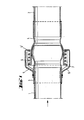
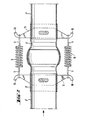
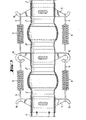
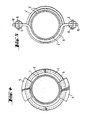
- a first embodiment of the system according to the present invention is shown, in which the two pipe hengths 1 and 2 of the exhaust line are joined by the universal ball joint consisting of the inner or inserted socket 3, joined to the pipe 1 upstream the joint, and the outer receiving socket 4, joined to the pipe 2 downstream of it, said joints being preferably carried out by welding or upsetting.
- circular sectors 5 are fixed, preferably by welding, forming at their opposite and a shoulder 5' for the helical compression spring 6, whose other end leans on the stop edge 7 made on the end of the outer socket 4.
Landscapes
- Engineering & Computer Science (AREA)
- General Engineering & Computer Science (AREA)
- Mechanical Engineering (AREA)
- Chemical & Material Sciences (AREA)
- Combustion & Propulsion (AREA)
- Cooling, Air Intake And Gas Exhaust, And Fuel Tank Arrangements In Propulsion Units (AREA)
- Vibration Prevention Devices (AREA)
- Joints Allowing Movement (AREA)
- Exhaust Silencers (AREA)
Applications Claiming Priority (2)
| Application Number | Priority Date | Filing Date | Title |
|---|---|---|---|
| IT8207202A IT1212600B (it) | 1982-01-26 | 1982-01-26 | Sistema di assorbimento delle vibrazioni per linee di scarico diveicoli a motore. |
| IT720282 | 1982-01-26 |
Publications (2)
| Publication Number | Publication Date |
|---|---|
| EP0084589A2 true EP0084589A2 (de) | 1983-08-03 |
| EP0084589A3 EP0084589A3 (de) | 1985-04-10 |
Family
ID=11124582
Family Applications (1)
| Application Number | Title | Priority Date | Filing Date |
|---|---|---|---|
| EP82104882A Withdrawn EP0084589A3 (de) | 1982-01-26 | 1982-06-03 | Vorrichtung zur Dämpfung von Vibrationen in Abgasleitungen von Motorfahrzeugen |
Country Status (2)
| Country | Link |
|---|---|
| EP (1) | EP0084589A3 (de) |
| IT (1) | IT1212600B (de) |
Cited By (6)
| Publication number | Priority date | Publication date | Assignee | Title |
|---|---|---|---|---|
| WO1987003038A1 (en) * | 1985-11-14 | 1987-05-21 | Fred Parker Birch | Flexible joint for connecting two pipes |
| GB2238838A (en) * | 1989-11-15 | 1991-06-12 | Ford Motor Co | Pipe coupling |
| EP0717225A1 (de) * | 1994-12-14 | 1996-06-19 | Mercedes-Benz Ag | Vorrichtung zur Verbindung von zwei rohrförmigen Leitungsteilen |
| EP0875707A3 (de) * | 1997-05-03 | 1999-07-07 | Volkswagen Aktiengesellschaft | Verbindungselement für zwei starre Rohre, insbesondere in Kraftfahrzeug-Abgasanlagen |
| CN105422243A (zh) * | 2015-12-29 | 2016-03-23 | 葛全岭 | 一种机动车消音排气管的减震装置 |
| CN112282913A (zh) * | 2020-11-17 | 2021-01-29 | 浙江春风动力股份有限公司 | 摩托车及排气管减振结构 |
Family Cites Families (3)
| Publication number | Priority date | Publication date | Assignee | Title |
|---|---|---|---|---|
| DE2353914A1 (de) * | 1973-10-27 | 1975-05-07 | Volkswagenwerk Ag | Gelenkige verbindung zweier rohre, insbesondere fuer abgasanlagen in kraftfahrzeugen |
| FR2346631A2 (fr) * | 1976-04-02 | 1977-10-28 | Chrysler France | Perfectionnements a un echappement de voiture |
| HU173328B (hu) * | 1976-12-22 | 1979-04-28 | Gany Mavag Mozdony Vagon Es Ge | Sfericheskoe sharnirnoe soedinenie trub mezhdu detaljami mashin, peremehhajuhhikhsja po otnosheniju drug-drugu vo vremja ehksploatacii |
-
1982
- 1982-01-26 IT IT8207202A patent/IT1212600B/it active
- 1982-06-03 EP EP82104882A patent/EP0084589A3/de not_active Withdrawn
Cited By (8)
| Publication number | Priority date | Publication date | Assignee | Title |
|---|---|---|---|---|
| WO1987003038A1 (en) * | 1985-11-14 | 1987-05-21 | Fred Parker Birch | Flexible joint for connecting two pipes |
| AU597015B2 (en) * | 1985-11-14 | 1990-05-24 | Fred Parker Birch | Flexible joint for connecting two axially spaced pipes in an engine exhaust system |
| GB2238838A (en) * | 1989-11-15 | 1991-06-12 | Ford Motor Co | Pipe coupling |
| EP0717225A1 (de) * | 1994-12-14 | 1996-06-19 | Mercedes-Benz Ag | Vorrichtung zur Verbindung von zwei rohrförmigen Leitungsteilen |
| US5873609A (en) * | 1994-12-14 | 1999-02-23 | Mercedes-Benz Ag | Device for connecting two tubular conducting parts |
| EP0875707A3 (de) * | 1997-05-03 | 1999-07-07 | Volkswagen Aktiengesellschaft | Verbindungselement für zwei starre Rohre, insbesondere in Kraftfahrzeug-Abgasanlagen |
| CN105422243A (zh) * | 2015-12-29 | 2016-03-23 | 葛全岭 | 一种机动车消音排气管的减震装置 |
| CN112282913A (zh) * | 2020-11-17 | 2021-01-29 | 浙江春风动力股份有限公司 | 摩托车及排气管减振结构 |
Also Published As
| Publication number | Publication date |
|---|---|
| IT1212600B (it) | 1989-11-30 |
| IT8207202A0 (it) | 1982-01-26 |
| EP0084589A3 (de) | 1985-04-10 |
Similar Documents
| Publication | Publication Date | Title |
|---|---|---|
| US4116411A (en) | Device for suspending an exhaust pipe in vehicles | |
| US2160808A (en) | Exhaust pipe and muffler support | |
| US5323989A (en) | Method of supporting exhaust pipe for motor vehicle and support structure for effecting the method | |
| CA2155915C (en) | Exhaust muffler bracket apparatus | |
| US20030057013A1 (en) | Vibration absorbing apparatus for exhaust system of engine | |
| CN103597179A (zh) | 板簧支架 | |
| EP0084589A2 (de) | Vorrichtung zur Dämpfung von Vibrationen in Abgasleitungen von Motorfahrzeugen | |
| EP0657683B1 (de) | Biegsame Vibrationsdämpfungsverbindung, insbesondere für Kraftfahrzeugabgasleitungen | |
| JPH06330913A (ja) | バンドクランプ部品の構造 | |
| US2020054A (en) | Automobile chassis construction | |
| JPH065117B2 (ja) | 配管連結リンク装置 | |
| CN110395240A (zh) | 一种具有分段式固定结构的气制动软管 | |
| US4074525A (en) | Exhaust device for a combustion engine | |
| JP2002070548A (ja) | エンジンの排気装置 | |
| US7419173B2 (en) | Supporting structure of stabilizer to vehicle body | |
| JP3591913B2 (ja) | パイプ材のフレキシブル連結構造 | |
| CN223120016U (zh) | 压气机的管路支架、压气机及车辆 | |
| JPH09268913A (ja) | エンジン排気系のフレキシブルチューブ | |
| JP3841393B2 (ja) | 排気管のフレキシブルジョイント構造 | |
| JPS5853608B2 (ja) | 車両用マフラの取付方法 | |
| JP3321924B2 (ja) | エンジンの排気装置 | |
| JPH0221544Y2 (de) | ||
| JPS6135687Y2 (de) | ||
| KR100501113B1 (ko) | 자동차 배기관용 코일 스프링 디커플러 구조 | |
| JPS6347613Y2 (de) |
Legal Events
| Date | Code | Title | Description |
|---|---|---|---|
| PUAI | Public reference made under article 153(3) epc to a published international application that has entered the european phase |
Free format text: ORIGINAL CODE: 0009012 |
|
| AK | Designated contracting states |
Designated state(s): AT BE CH DE FR GB IT LI LU NL SE |
|
| PUAL | Search report despatched |
Free format text: ORIGINAL CODE: 0009013 |
|
| AK | Designated contracting states |
Designated state(s): AT BE CH DE FR GB IT LI LU NL SE |
|
| STAA | Information on the status of an ep patent application or granted ep patent |
Free format text: STATUS: THE APPLICATION IS DEEMED TO BE WITHDRAWN |
|
| 18D | Application deemed to be withdrawn |
Effective date: 19851211 |
|
| RIN1 | Information on inventor provided before grant (corrected) |
Inventor name: SALA, ALFREDO Inventor name: MARZORATI, ATTILIO |