EP0084485B1 - Noeud d'assemblage de structures métalliques tubulaires, notamment pour plates-formes de forage - Google Patents
Noeud d'assemblage de structures métalliques tubulaires, notamment pour plates-formes de forage Download PDFInfo
- Publication number
- EP0084485B1 EP0084485B1 EP83400066A EP83400066A EP0084485B1 EP 0084485 B1 EP0084485 B1 EP 0084485B1 EP 83400066 A EP83400066 A EP 83400066A EP 83400066 A EP83400066 A EP 83400066A EP 0084485 B1 EP0084485 B1 EP 0084485B1
- Authority
- EP
- European Patent Office
- Prior art keywords
- stiffening
- nodal point
- tubular element
- stiffening element
- tubular
- Prior art date
- Legal status (The legal status is an assumption and is not a legal conclusion. Google has not performed a legal analysis and makes no representation as to the accuracy of the status listed.)
- Expired
Links
Images
Classifications
-
- E—FIXED CONSTRUCTIONS
- E02—HYDRAULIC ENGINEERING; FOUNDATIONS; SOIL SHIFTING
- E02B—HYDRAULIC ENGINEERING
- E02B17/00—Artificial islands mounted on piles or like supports, e.g. platforms on raisable legs or offshore constructions; Construction methods therefor
- E02B17/0004—Nodal points
-
- E—FIXED CONSTRUCTIONS
- E04—BUILDING
- E04B—GENERAL BUILDING CONSTRUCTIONS; WALLS, e.g. PARTITIONS; ROOFS; FLOORS; CEILINGS; INSULATION OR OTHER PROTECTION OF BUILDINGS
- E04B1/00—Constructions in general; Structures which are not restricted either to walls, e.g. partitions, or floors or ceilings or roofs
- E04B1/38—Connections for building structures in general
- E04B1/58—Connections for building structures in general of bar-shaped building elements
- E04B1/5825—Connections for building structures in general of bar-shaped building elements with a closed cross-section
- E04B1/5837—Connections for building structures in general of bar-shaped building elements with a closed cross-section of substantially circular form
Definitions
- the present invention relates to a node for assembling tubular metal structures, in particular for offshore drilling platforms.
- Offshore drilling platforms are often made using assemblies of tubular structures. Due to the particularly difficult working conditions of such platforms, which result in particular from the existence of swell, the fatigue life of their components, and especially of the assembly nodes, is of very particular importance. However, the fatigue life is a function of the rigidity of the tubes used in the production of the platforms. This is the reason why we have had to have stiffening elements inside the tubes of the structure, at the locations of the intersections of the tubes or assembly nodes, when the diameter of these tubes allows. These stiffeners, generally made in the form of hoops, constitute a very expensive solution, since their installation requires in particular the production of welds inside the tubes (see for example DE-A-2626867 and US-A- 3134235).
- the present invention proposes to provide an economical solution, easy to implement and offering all the guarantees of security, to the problems posed by the production of tubular assemblies of all dimensions.
- a node for assembling tubular metallic structures in particular for drilling platforms, characterized in that it comprises, in the tubular element on which the tubes constituting the node are welded, at least one Welded or cast steel stiffening element, comprising a main cylindrical part coaxial with said tubular element and provided with annular ribs, said stiffening element being hooped in the tubular element with a sufficient hooping rate to prevent its separation from the tubular element.
- said stiffening element is constituted by the stacking of a plurality of elementary stiffening elements hooped in said tubular element, each of these elementary stiffeners comprising a cylindrical part and annular ribs.
- weld beads are provided on the end ribs of the stiffening element or elements, in order to seal the enclosures delimited between the ribs relative to the tubular element, these enclosures being able to be then put under overpressure or under vacuum to detect the possible presence of through cracks at the assembly node.
- the or each stiffening element can be provided with a network of longitudinal stiffeners.
- Fig. 1 schematically illustrates the tubular structure of a drilling platform to which the invention can be applied.
- this structure consists of an assembly of tubes 10, 12, of more or less large diameters, and the invention relates to the assembly nodes, such as 14, of this tubular structure.
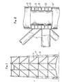
- FIG. 2 illustrates a first embodiment of the invention.
- the stiffening element according to the invention disposed in the tubular element 10, comprises a tubular part 16 coaxial with the tubular element, and annular ribs 18.
- This stiffening element which can be made in molded or welded steel is hooped in the tubular element 10 with a sufficient hooping rate to avoid its separation by detachment.
- weld beads 20, 20 ′ are provided on the periphery of the end ribs of the stiffening element. It is thus possible to isolate from the internal bore of the tube 10, and to make watertight vis-à-vis the outside, the capacities 22, delimited between the ribs 18 consecutive. By putting these capacities 22 in depression or in overpressure by injecting a gas therein, for example air, one can detect the through cracks likely to occur in the tubular element 10, at the level of its connection with the tubes 12.
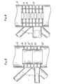
- the stiffening element is constituted by the stacking of unit elements (two in this example) 24-24 ', each of these elements having the characteristics of the stiffening element of FIG. 2.
- unit elements two in this example
- 26 ', 26 " weld beads similar to the beads 20, 20' of FIG. 2, and intended to perform the same functions.
- the variant shown in FIG. 4 differs from the embodiment illustrated in FIG. 2 in that the stiffening element is provided with diaphragms or stiffening hoops 28, which further increase the rigidity.
- the stiffening element can also be provided with a network of longitudinal or oblique stiffeners.
Landscapes
- Engineering & Computer Science (AREA)
- Architecture (AREA)
- Civil Engineering (AREA)
- Structural Engineering (AREA)
- General Engineering & Computer Science (AREA)
- Physics & Mathematics (AREA)
- Electromagnetism (AREA)
- Mechanical Engineering (AREA)
- Earth Drilling (AREA)
- Joining Of Building Structures In Genera (AREA)
- Rod-Shaped Construction Members (AREA)
- Butt Welding And Welding Of Specific Article (AREA)
Applications Claiming Priority (2)
| Application Number | Priority Date | Filing Date | Title |
|---|---|---|---|
| FR8200521 | 1982-01-14 | ||
| FR8200521A FR2519734A1 (fr) | 1982-01-14 | 1982-01-14 | Noeud d'assemblage de structures metalliques tubulaires, notamment pour plates-formes de forage |
Publications (2)
| Publication Number | Publication Date |
|---|---|
| EP0084485A1 EP0084485A1 (fr) | 1983-07-27 |
| EP0084485B1 true EP0084485B1 (fr) | 1985-08-14 |
Family
ID=9269983
Family Applications (1)
| Application Number | Title | Priority Date | Filing Date |
|---|---|---|---|
| EP83400066A Expired EP0084485B1 (fr) | 1982-01-14 | 1983-01-12 | Noeud d'assemblage de structures métalliques tubulaires, notamment pour plates-formes de forage |
Country Status (8)
| Country | Link |
|---|---|
| US (1) | US4907913A (cg-RX-API-DMAC7.html) |
| EP (1) | EP0084485B1 (cg-RX-API-DMAC7.html) |
| JP (1) | JPS58127849A (cg-RX-API-DMAC7.html) |
| DE (2) | DE3360532D1 (cg-RX-API-DMAC7.html) |
| ES (1) | ES518732A0 (cg-RX-API-DMAC7.html) |
| FR (1) | FR2519734A1 (cg-RX-API-DMAC7.html) |
| MX (1) | MX158438A (cg-RX-API-DMAC7.html) |
| NO (1) | NO164493C (cg-RX-API-DMAC7.html) |
Families Citing this family (1)
| Publication number | Priority date | Publication date | Assignee | Title |
|---|---|---|---|---|
| WO2010141700A1 (en) * | 2009-06-03 | 2010-12-09 | Keystone Engineering, Inc. | Pile splice and method of forming a pile splice |
Family Cites Families (5)
| Publication number | Priority date | Publication date | Assignee | Title |
|---|---|---|---|---|
| US3134235A (en) * | 1959-11-12 | 1964-05-26 | Jersey Prod Res Co | Installation of piling |
| US3485050A (en) * | 1967-10-12 | 1969-12-23 | Shell Oil Co | Marine structures |
| US3550384A (en) * | 1969-02-07 | 1970-12-29 | Exxon Production Research Co | Lateral restraint of pile within jacket leg |
| DE2626867C2 (de) * | 1976-06-16 | 1983-03-24 | Thyssen Industrie Ag, 4300 Essen | Aus Teilen zusammengeschweißtes Rohr |
| FR2495773A1 (fr) * | 1980-12-04 | 1982-06-11 | Petroles Cie Francaise | Plate-forme marine munie de moyens de detection d'eventuelles fissures |
-
1982
- 1982-01-14 FR FR8200521A patent/FR2519734A1/fr active Granted
- 1982-12-30 ES ES518732A patent/ES518732A0/es active Granted
-
1983
- 1983-01-12 DE DE8383400066T patent/DE3360532D1/de not_active Expired
- 1983-01-12 MX MX195894A patent/MX158438A/es unknown
- 1983-01-12 DE DE198383400066T patent/DE84485T1/de active Pending
- 1983-01-12 EP EP83400066A patent/EP0084485B1/fr not_active Expired
- 1983-01-13 NO NO830091A patent/NO164493C/no unknown
- 1983-01-14 US US07/458,052 patent/US4907913A/en not_active Expired - Fee Related
- 1983-01-14 JP JP58005158A patent/JPS58127849A/ja active Granted
Also Published As
| Publication number | Publication date |
|---|---|
| DE3360532D1 (en) | 1985-09-19 |
| FR2519734B1 (cg-RX-API-DMAC7.html) | 1984-05-04 |
| JPH049894B2 (cg-RX-API-DMAC7.html) | 1992-02-21 |
| ES8401219A1 (es) | 1983-12-16 |
| ES518732A0 (es) | 1983-12-16 |
| NO164493C (no) | 1990-10-10 |
| NO830091L (no) | 1983-07-15 |
| EP0084485A1 (fr) | 1983-07-27 |
| MX158438A (es) | 1989-01-31 |
| JPS58127849A (ja) | 1983-07-30 |
| DE84485T1 (de) | 1984-03-29 |
| US4907913A (en) | 1990-03-13 |
| NO164493B (no) | 1990-07-02 |
| FR2519734A1 (fr) | 1983-07-18 |
Similar Documents
| Publication | Publication Date | Title |
|---|---|---|
| FR2807138A1 (fr) | Element filete tubulaire pour joint filete tubulaire resistant a la fatigue et joint filete tubulaire resultant | |
| EP1257763A1 (fr) | Dispositif de protection cathodique des conduites flexibles | |
| FR2549194A1 (fr) | Raccord pour circuits a haute pression | |
| FR2512906A1 (fr) | Amortisseur hydraulique telescopique a deux tubes | |
| EP0126698B1 (fr) | Méthode d'assemblage d'un élément annulaire sur un tube métallique en aluminium ou un de ses alliages | |
| FR2828262A1 (fr) | Element de conduite haute pression en tube frette | |
| FR2568979A1 (fr) | Assemblage telescopique perfectionne pour reparer des canalisations sous-marines posees a de grandes profondeurs | |
| EP0176407B1 (fr) | Collecteur pour échangeur de chaleur, et échangeur de chaleur comprenant ce collecteur | |
| EP0084485B1 (fr) | Noeud d'assemblage de structures métalliques tubulaires, notamment pour plates-formes de forage | |
| FR2545147A1 (fr) | Ensemble d'accouplements de tube prolongateur marin | |
| EP0043299A1 (fr) | Réservoir à suspension antivibratoire | |
| FR2746889A1 (fr) | Joint d'etancheite, notamment pour verin pneumatique ou hydraulique | |
| EP3022477A1 (fr) | Embout de connexion d'une conduite flexible, et conduite flexible associée | |
| FR2873800A1 (fr) | Echangeur de chaleur a assemblage mecanique et joint d'etancheite pour cet echangeur de chaleur | |
| EP0565466A1 (fr) | Elément flexible de tuyauterie, notamment pour lignes d'échappement de véhicules automobiles et son procédé de fabrication | |
| FR2559869A1 (fr) | Vanne d'arret | |
| FR2672372A1 (fr) | Dispositif de jonction etanche entre deux tuyaux cylindriques. | |
| FR2602205A1 (fr) | Ensemble de reprise des efforts d'au moins un hauban | |
| EP1443239B1 (fr) | Articulation antivibratoire hydraulique à butées axiales, véhicule équipé d'un telle articulation, et procédé de fabrication d'un telle articulation | |
| FR2708983A1 (fr) | Bague d'étanchéité destinée à être disposée entre deux brides. | |
| EP0322294B2 (fr) | Procédé de montage d'un accumulateur hydropneumatique | |
| FR2509211A1 (fr) | Procede de soudage de joints circulaires de tubes et dispositif pour la mise en oeuvre de ce procede | |
| EP1038714B1 (fr) | Raccordement entre deux éléments cylinderiques | |
| EP0100578B1 (fr) | Raccord de dérivation | |
| WO2000065273A1 (fr) | Embout de raccordement de reservoir d'air comprime ou autres gaz a haute pression et circulation interne du fluide |
Legal Events
| Date | Code | Title | Description |
|---|---|---|---|
| PUAI | Public reference made under article 153(3) epc to a published international application that has entered the european phase |
Free format text: ORIGINAL CODE: 0009012 |
|
| AK | Designated contracting states |
Designated state(s): BE DE GB IT NL SE |
|
| ITCL | It: translation for ep claims filed |
Representative=s name: STUDIO KOHLER FONTANA |
|
| TCNL | Nl: translation of patent claims filed | ||
| 17P | Request for examination filed |
Effective date: 19840116 |
|
| DET | De: translation of patent claims | ||
| ITF | It: translation for a ep patent filed | ||
| GRAA | (expected) grant |
Free format text: ORIGINAL CODE: 0009210 |
|
| AK | Designated contracting states |
Designated state(s): BE DE GB IT NL SE |
|
| REF | Corresponds to: |
Ref document number: 3360532 Country of ref document: DE Date of ref document: 19850919 |
|
| PLBE | No opposition filed within time limit |
Free format text: ORIGINAL CODE: 0009261 |
|
| STAA | Information on the status of an ep patent application or granted ep patent |
Free format text: STATUS: NO OPPOSITION FILED WITHIN TIME LIMIT |
|
| 26N | No opposition filed | ||
| PGFP | Annual fee paid to national office [announced via postgrant information from national office to epo] |
Ref country code: NL Payment date: 19870131 Year of fee payment: 5 |
|
| PG25 | Lapsed in a contracting state [announced via postgrant information from national office to epo] |
Ref country code: SE Effective date: 19880113 |
|
| BERE | Be: lapsed |
Owner name: SOC. FRANCAISE D'ETUDES D'INSTALLATIONS SIDERURGIQ Effective date: 19880131 |
|
| PG25 | Lapsed in a contracting state [announced via postgrant information from national office to epo] |
Ref country code: NL Effective date: 19880801 |
|
| NLV4 | Nl: lapsed or anulled due to non-payment of the annual fee | ||
| PG25 | Lapsed in a contracting state [announced via postgrant information from national office to epo] |
Ref country code: BE Effective date: 19890131 |
|
| ITTA | It: last paid annual fee | ||
| PGFP | Annual fee paid to national office [announced via postgrant information from national office to epo] |
Ref country code: DE Payment date: 19910402 Year of fee payment: 9 |
|
| PGFP | Annual fee paid to national office [announced via postgrant information from national office to epo] |
Ref country code: GB Payment date: 19920113 Year of fee payment: 10 |
|
| PG25 | Lapsed in a contracting state [announced via postgrant information from national office to epo] |
Ref country code: DE Effective date: 19921001 |
|
| PG25 | Lapsed in a contracting state [announced via postgrant information from national office to epo] |
Ref country code: GB Effective date: 19930112 |
|
| GBPC | Gb: european patent ceased through non-payment of renewal fee |
Effective date: 19930112 |
|
| EUG | Se: european patent has lapsed |
Ref document number: 83400066.3 Effective date: 19880913 |