EP0084485B1 - Nodal point for the constructions of metallic tubes, especially for drilling platforms - Google Patents
Nodal point for the constructions of metallic tubes, especially for drilling platforms Download PDFInfo
- Publication number
- EP0084485B1 EP0084485B1 EP83400066A EP83400066A EP0084485B1 EP 0084485 B1 EP0084485 B1 EP 0084485B1 EP 83400066 A EP83400066 A EP 83400066A EP 83400066 A EP83400066 A EP 83400066A EP 0084485 B1 EP0084485 B1 EP 0084485B1
- Authority
- EP
- European Patent Office
- Prior art keywords
- stiffening
- nodal point
- tubular element
- stiffening element
- tubular
- Prior art date
- Legal status (The legal status is an assumption and is not a legal conclusion. Google has not performed a legal analysis and makes no representation as to the accuracy of the status listed.)
- Expired
Links
Images
Classifications
-
- E—FIXED CONSTRUCTIONS
- E02—HYDRAULIC ENGINEERING; FOUNDATIONS; SOIL SHIFTING
- E02B—HYDRAULIC ENGINEERING
- E02B17/00—Artificial islands mounted on piles or like supports, e.g. platforms on raisable legs or offshore constructions; Construction methods therefor
- E02B17/0004—Nodal points
-
- E—FIXED CONSTRUCTIONS
- E04—BUILDING
- E04B—GENERAL BUILDING CONSTRUCTIONS; WALLS, e.g. PARTITIONS; ROOFS; FLOORS; CEILINGS; INSULATION OR OTHER PROTECTION OF BUILDINGS
- E04B1/00—Constructions in general; Structures which are not restricted either to walls, e.g. partitions, or floors or ceilings or roofs
- E04B1/38—Connections for building structures in general
- E04B1/58—Connections for building structures in general of bar-shaped building elements
- E04B1/5825—Connections for building structures in general of bar-shaped building elements with a closed cross-section
- E04B1/5837—Connections for building structures in general of bar-shaped building elements with a closed cross-section of substantially circular form
Definitions
- the present invention relates to a node for assembling tubular metal structures, in particular for offshore drilling platforms.
- Offshore drilling platforms are often made using assemblies of tubular structures. Due to the particularly difficult working conditions of such platforms, which result in particular from the existence of swell, the fatigue life of their components, and especially of the assembly nodes, is of very particular importance. However, the fatigue life is a function of the rigidity of the tubes used in the production of the platforms. This is the reason why we have had to have stiffening elements inside the tubes of the structure, at the locations of the intersections of the tubes or assembly nodes, when the diameter of these tubes allows. These stiffeners, generally made in the form of hoops, constitute a very expensive solution, since their installation requires in particular the production of welds inside the tubes (see for example DE-A-2626867 and US-A- 3134235).
- the present invention proposes to provide an economical solution, easy to implement and offering all the guarantees of security, to the problems posed by the production of tubular assemblies of all dimensions.
- a node for assembling tubular metallic structures in particular for drilling platforms, characterized in that it comprises, in the tubular element on which the tubes constituting the node are welded, at least one Welded or cast steel stiffening element, comprising a main cylindrical part coaxial with said tubular element and provided with annular ribs, said stiffening element being hooped in the tubular element with a sufficient hooping rate to prevent its separation from the tubular element.
- said stiffening element is constituted by the stacking of a plurality of elementary stiffening elements hooped in said tubular element, each of these elementary stiffeners comprising a cylindrical part and annular ribs.
- weld beads are provided on the end ribs of the stiffening element or elements, in order to seal the enclosures delimited between the ribs relative to the tubular element, these enclosures being able to be then put under overpressure or under vacuum to detect the possible presence of through cracks at the assembly node.
- the or each stiffening element can be provided with a network of longitudinal stiffeners.
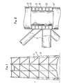
- Fig. 1 schematically illustrates the tubular structure of a drilling platform to which the invention can be applied.
- this structure consists of an assembly of tubes 10, 12, of more or less large diameters, and the invention relates to the assembly nodes, such as 14, of this tubular structure.
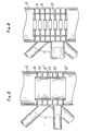
- FIG. 2 illustrates a first embodiment of the invention.
- the stiffening element according to the invention disposed in the tubular element 10, comprises a tubular part 16 coaxial with the tubular element, and annular ribs 18.
- This stiffening element which can be made in molded or welded steel is hooped in the tubular element 10 with a sufficient hooping rate to avoid its separation by detachment.
- weld beads 20, 20 ′ are provided on the periphery of the end ribs of the stiffening element. It is thus possible to isolate from the internal bore of the tube 10, and to make watertight vis-à-vis the outside, the capacities 22, delimited between the ribs 18 consecutive. By putting these capacities 22 in depression or in overpressure by injecting a gas therein, for example air, one can detect the through cracks likely to occur in the tubular element 10, at the level of its connection with the tubes 12.
- the stiffening element is constituted by the stacking of unit elements (two in this example) 24-24 ', each of these elements having the characteristics of the stiffening element of FIG. 2.
- unit elements two in this example
- 26 ', 26 " weld beads similar to the beads 20, 20' of FIG. 2, and intended to perform the same functions.
- the variant shown in FIG. 4 differs from the embodiment illustrated in FIG. 2 in that the stiffening element is provided with diaphragms or stiffening hoops 28, which further increase the rigidity.
- the stiffening element can also be provided with a network of longitudinal or oblique stiffeners.
Landscapes
- Engineering & Computer Science (AREA)
- Architecture (AREA)
- Civil Engineering (AREA)
- Structural Engineering (AREA)
- General Engineering & Computer Science (AREA)
- Physics & Mathematics (AREA)
- Electromagnetism (AREA)
- Mechanical Engineering (AREA)
- Earth Drilling (AREA)
- Joining Of Building Structures In Genera (AREA)
- Butt Welding And Welding Of Specific Article (AREA)
- Rod-Shaped Construction Members (AREA)
Abstract
Description
La présente invention est relative à un noeud d'assemblage de structures métalliques tubulaires, notamment pour plates-formes de forage en mer.The present invention relates to a node for assembling tubular metal structures, in particular for offshore drilling platforms.
Les plates-formes de forage en mer sont souvent réalisées à l'aide d'assemblages de structures tubulaires. En raison des conditions de travail particulièrement difficiles de telles plates-formes, qui résultent notamment de l'existence de la houle, la tenue à la fatigue de leurs composants, et spécialement des noeuds d'assemblage, revêt une importance toute particulière. Or, la tenue à la fatigue est fonction de la rigidité des tubes rentrant dans la réalisation des plates-formes. C'est la raison pour laquelle on a été amené à disposer des éléments de raidissement à l'intérieur des tubes de la structure, aux emplacements des intersections des tubes ou nœuds d'assemblage, lorsque le diamètre de ces tubes le permet. Ces raidisseurs, réalisés généralement sous la forme de cerces, constituent une solution très coûteuse, car leur mise en place exige notamment la réalisation de soudures à l'intérieur des tubes (voir par exemple le DE-A-2626867 et le US-A-3134235).Offshore drilling platforms are often made using assemblies of tubular structures. Due to the particularly difficult working conditions of such platforms, which result in particular from the existence of swell, the fatigue life of their components, and especially of the assembly nodes, is of very particular importance. However, the fatigue life is a function of the rigidity of the tubes used in the production of the platforms. This is the reason why we have had to have stiffening elements inside the tubes of the structure, at the locations of the intersections of the tubes or assembly nodes, when the diameter of these tubes allows. These stiffeners, generally made in the form of hoops, constitute a very expensive solution, since their installation requires in particular the production of welds inside the tubes (see for example DE-A-2626867 and US-A- 3134235).
La présente invention se propose d'apporter une solution économique, facile à mettre en oeuvre et offrant toutes les garanties de sécurité, aux problèmes posés par la réalisation d'assemblages tubulaires de toutes dimensions.The present invention proposes to provide an economical solution, easy to implement and offering all the guarantees of security, to the problems posed by the production of tubular assemblies of all dimensions.
A cet effet, elle vise un noeud d'assemblage de structures métalliques tubulaires, notamment pour plates-formes de forage, caractérisé en ce qu'il comporte, dans l'élément tubulaire sur lequel sont soudés les tubes constituant le noeud, au moins un élément raidisseur en acier soudé ou moulé, comportant une partie principale cylindrique coaxiale audit élément tubulaire et munie de nervures annulaires, ledit élément raidisseur étant fretté dans l'élément tubulaire avec un taux de frettage suffisant pour empêcher sa désolidarisation de l'élément tubulaire.To this end, it relates to a node for assembling tubular metallic structures, in particular for drilling platforms, characterized in that it comprises, in the tubular element on which the tubes constituting the node are welded, at least one Welded or cast steel stiffening element, comprising a main cylindrical part coaxial with said tubular element and provided with annular ribs, said stiffening element being hooped in the tubular element with a sufficient hooping rate to prevent its separation from the tubular element.
Selon une autre caractéristique de cette invention, ledit élément raidisseur est constitué par l'empilage d'une pluralité d'éléments raidisseurs élémentaires frettés dans ledit élément tubulaire, chacun de ces raidisseurs élémentaires comportant une partie cylindrique et des nervures annulaires.According to another characteristic of this invention, said stiffening element is constituted by the stacking of a plurality of elementary stiffening elements hooped in said tubular element, each of these elementary stiffeners comprising a cylindrical part and annular ribs.
Selon encore une autre caractéristique de cette invention, on prévoit des cordons de soudure sur les nervures d'extrémités du ou des éléments raidisseurs, pour assurer l'étanchéité des enceintes délimitées entre les nervures par rapport à l'élément tubulaire, ces enceintes pouvant être ensuite mises en surpression ou en dépression pour détecter la présence éventuelle de fissures traversantes au niveau du noeud d'assemblage.According to yet another characteristic of this invention, weld beads are provided on the end ribs of the stiffening element or elements, in order to seal the enclosures delimited between the ribs relative to the tubular element, these enclosures being able to be then put under overpressure or under vacuum to detect the possible presence of through cracks at the assembly node.
Selon encore une autre caractéristique de cette invention, le ou chaque élément raidisseur peut être muni d'un réseau de raidisseurs longitudinaux.According to yet another characteristic of this invention, the or each stiffening element can be provided with a network of longitudinal stiffeners.
D'autres caractéristiques et avantages de cette invention ressortiront de la description faite ci-après en référence aux dessins annexés, qui en illustrent divers exemples de réalisation. Sur les dessins:
- la fig. 1 est une vue schématique représentant une structure tubulaire de plate forme de forage à laquelle l'invention peut-être appliquée,
- la fig. 2 est une vue en coupe axiale verticale partielle d'un noeud d'assemblage muni d'un élément raidisseur selon l'invention, et
- les fig. 3 et 4 sont des vues similaires à la fig. 2, illustrant deux variantes de l'invention.
- fig. 1 is a schematic view showing a tubular structure of a drilling platform to which the invention can be applied,
- fig. 2 is a view in partial vertical axial section of an assembly node provided with a stiffening element according to the invention, and
- fig. 3 and 4 are views similar to FIG. 2, illustrating two variants of the invention.
La fig. 1 illustre de façon schématique la structure tubulaire d'une plate-forme de forage à laquelle l'invention peut être appliquée. Comme connu, cette structure est constituée d'un assemblage de tubes 10,12, de diamètres plus ou moins importants, et l'invention concerne les noeuds d'assemblage, tels que 14, de cette structure tubulaire.Fig. 1 schematically illustrates the tubular structure of a drilling platform to which the invention can be applied. As known, this structure consists of an assembly of
On se réfère maintenant à la fig. 2, qui illustre un premier exemple de réalisation de l'invention. Sur cette figure, on voit que l'élément raidisseur selon l'invention, disposé dans l'élément tubulaire 10, comprend une partie tubulaire 16 coaxiale à l'élément tubulaire, et des nervures annulaires 18. Cet élément raidisseur, pouvant être réalisé en acier moulé ou soudé, est fretté dans l'élément tubulaire 10 avec un taux de frettage suffisant pour éviter sa désolidarisation par décollement.We now refer to FIG. 2, which illustrates a first embodiment of the invention. In this figure, it can be seen that the stiffening element according to the invention, disposed in the
Dans cet exemple de réalisation, on prévoit des cordons de soudure 20, 20' sur la périphérie des nervures d'extrémités de l'élément raidisseur. On peut ainsi isoler de l'alésage interne du tube 10, et rendre étanches vis-à-vis de l'extérieur, les capacités 22, délimitées entre les nervures 18 consécutives. En mettant ces capacités 22 en dépression ou en surpression en y injectant un gaz, par exemple de l'air, on peut détecter les fissures traversantes susceptibles de se produire dans l'élément tubulaire 10, au niveau de sa liaison avec les tubes 12.In this exemplary embodiment,
Dans le mode d'exécution représenté sur la fig. 3, l'élément raidisseur est constitué par l'empilage d'éléments unitaires (deux dans cet exemple) 24-24', chacun de ces éléments présentant les caractéristiques de l'élément raidisseur de la fig. 2. Sur le dessin, on a représenté, en 26, 26', 26", des cordons de soudure analogues aux cordons 20, 20' de la fig. 2, et destinés à jouer les mêmes fonctions.In the embodiment shown in FIG. 3, the stiffening element is constituted by the stacking of unit elements (two in this example) 24-24 ', each of these elements having the characteristics of the stiffening element of FIG. 2. In the drawing, there are shown, at 26, 26 ', 26 ", weld beads similar to the
La variante représentée sur la fig. 4 diffère de l'exemple de réalisation illustré par la fig. 2 en ce que l'élément raidisseur est muni de diaphragmes ou cerces de raidissement 28, qui augmentent encore la rigidité. L'élément raidisseur peut être également pourvu d'un réseau de raidisseurs longitudinaux ou obliques.The variant shown in FIG. 4 differs from the embodiment illustrated in FIG. 2 in that the stiffening element is provided with diaphragms or
Parmi les avantages apportés par l'invention, on peut citer notamment:
- - réalisation et montage faciles, par simple frettage dans un élément tubulaire de la structure, quelles que soient les dimensions de cet élément;
- - bas prix de revient, et pose bon marché;
- - réduction du coefficient de concentration des contraintes au niveau des noeuds d'assemblage, ce qui améliore la tenue à la fatigue;
- - possibilité, au moyen d'une adaptation peu coûteuse (cordons de soudure sur les nervures d'extrémité), de détecter les fissures traversantes au niveau des interconnexions.
- - Easy realization and assembly, by simple hooping in a tubular element of the structure, whatever the dimensions of this element;
- - low cost price, and cheap installation;
- - reduction of the stress concentration coefficient at the assembly nodes, which improves resistance to fatigue;
- - possibility, by means of little adaptation expensive (weld seams on the end ribs), to detect through cracks at the interconnections.
Claims (6)
Applications Claiming Priority (2)
| Application Number | Priority Date | Filing Date | Title |
|---|---|---|---|
| FR8200521A FR2519734A1 (en) | 1982-01-14 | 1982-01-14 | NODE FOR ASSEMBLING TUBULAR METAL STRUCTURES, PARTICULARLY FOR DRILLING PLATFORMS |
| FR8200521 | 1982-01-14 |
Publications (2)
| Publication Number | Publication Date |
|---|---|
| EP0084485A1 EP0084485A1 (en) | 1983-07-27 |
| EP0084485B1 true EP0084485B1 (en) | 1985-08-14 |
Family
ID=9269983
Family Applications (1)
| Application Number | Title | Priority Date | Filing Date |
|---|---|---|---|
| EP83400066A Expired EP0084485B1 (en) | 1982-01-14 | 1983-01-12 | Nodal point for the constructions of metallic tubes, especially for drilling platforms |
Country Status (8)
| Country | Link |
|---|---|
| US (1) | US4907913A (en) |
| EP (1) | EP0084485B1 (en) |
| JP (1) | JPS58127849A (en) |
| DE (2) | DE84485T1 (en) |
| ES (1) | ES518732A0 (en) |
| FR (1) | FR2519734A1 (en) |
| MX (1) | MX158438A (en) |
| NO (1) | NO164493C (en) |
Families Citing this family (1)
| Publication number | Priority date | Publication date | Assignee | Title |
|---|---|---|---|---|
| US8444349B2 (en) * | 2009-06-03 | 2013-05-21 | Keystone Engineering Inc. | Grouted pile splice and method of forming a grouted pile splice |
Family Cites Families (5)
| Publication number | Priority date | Publication date | Assignee | Title |
|---|---|---|---|---|
| US3134235A (en) * | 1959-11-12 | 1964-05-26 | Jersey Prod Res Co | Installation of piling |
| US3485050A (en) * | 1967-10-12 | 1969-12-23 | Shell Oil Co | Marine structures |
| US3550384A (en) * | 1969-02-07 | 1970-12-29 | Exxon Production Research Co | Lateral restraint of pile within jacket leg |
| DE2626867C2 (en) * | 1976-06-16 | 1983-03-24 | Thyssen Industrie Ag, 4300 Essen | Pipe welded together from parts |
| FR2495773A1 (en) * | 1980-12-04 | 1982-06-11 | Petroles Cie Francaise | MARINE PLATFORM PROVIDED WITH MEANS FOR DETECTION OF POSSIBLE CRACKS |
-
1982
- 1982-01-14 FR FR8200521A patent/FR2519734A1/en active Granted
- 1982-12-30 ES ES518732A patent/ES518732A0/en active Granted
-
1983
- 1983-01-12 DE DE198383400066T patent/DE84485T1/en active Pending
- 1983-01-12 MX MX195894A patent/MX158438A/en unknown
- 1983-01-12 EP EP83400066A patent/EP0084485B1/en not_active Expired
- 1983-01-12 DE DE8383400066T patent/DE3360532D1/en not_active Expired
- 1983-01-13 NO NO830091A patent/NO164493C/en unknown
- 1983-01-14 US US07/458,052 patent/US4907913A/en not_active Expired - Fee Related
- 1983-01-14 JP JP58005158A patent/JPS58127849A/en active Granted
Also Published As
| Publication number | Publication date |
|---|---|
| ES8401219A1 (en) | 1983-12-16 |
| US4907913A (en) | 1990-03-13 |
| NO830091L (en) | 1983-07-15 |
| JPH049894B2 (en) | 1992-02-21 |
| NO164493C (en) | 1990-10-10 |
| FR2519734B1 (en) | 1984-05-04 |
| ES518732A0 (en) | 1983-12-16 |
| EP0084485A1 (en) | 1983-07-27 |
| DE3360532D1 (en) | 1985-09-19 |
| DE84485T1 (en) | 1984-03-29 |
| MX158438A (en) | 1989-01-31 |
| FR2519734A1 (en) | 1983-07-18 |
| NO164493B (en) | 1990-07-02 |
| JPS58127849A (en) | 1983-07-30 |
Similar Documents
| Publication | Publication Date | Title |
|---|---|---|
| CA1203178A (en) | Device with hose, especially for expandable blowout preventer | |
| FR2807138A1 (en) | TUBULAR THREADED ELEMENT FOR FATIGUE-RESISTANT TUBULAR THREAD SEAL AND THREADED TUBULAR SEAL | |
| FR2549194A1 (en) | CONNECTION FOR HIGH PRESSURE CIRCUITS | |
| FR2512906A1 (en) | TELESCOPIC HYDRAULIC SHOCK ABSORBER WITH TWO TUBES | |
| EP0126698B1 (en) | Method of affixing an annular member on an aluminium tube or the like | |
| FR2828262A1 (en) | HIGH PRESSURE CONDUCTOR IN A FREIGHT TUBE | |
| FR2568979A1 (en) | ADVANCED TELESCOPIC ASSEMBLY TO REPAIR UNDERWATER PIPES WITH LARGE DEPTHS | |
| EP0176407B1 (en) | Header box for a heat exchanger and heat exchanger comprising this header box | |
| EP1512794B1 (en) | Device for damping of vibrations in cables and method therefor | |
| EP0084485B1 (en) | Nodal point for the constructions of metallic tubes, especially for drilling platforms | |
| EP0043299A1 (en) | Reservoir with vibration damping suspension | |
| FR2873800A1 (en) | HEAT EXCHANGER WITH MECHANICAL ASSEMBLY AND SEAL FOR THIS HEAT EXCHANGER | |
| EP0565466A1 (en) | Flexible piping element, especially for exhaust lines of automobiles and its manufacturing process | |
| BE559369A (en) | ||
| WO2015007854A1 (en) | Connection end piece of a flexible pipe, and associated flexible pipe | |
| FR2602205A1 (en) | ENSEMBLE OF RECOVERY OF EFFORTS OF AT LEAST ONE HAUBAN | |
| FR2708983A1 (en) | Sealing ring designed to be placed between two flanges | |
| EP0322294B2 (en) | Method for mounting a hydropneumatic accumulator | |
| FR2509211A1 (en) | METHOD FOR WELDING TUBE CIRCULAR JOINTS AND DEVICE FOR CARRYING OUT SAID METHOD | |
| FR2559869A1 (en) | THE STOP VALVE | |
| EP1038714B1 (en) | Connection between two cylindrical elements | |
| EP0100578B1 (en) | Branch coupling | |
| FR2475685A1 (en) | Ball joint vehicle exhaust pipe - uses part spherical spigot in collar socket with outer collar sprung with axial and radial float | |
| FR2742833A1 (en) | HYDRAULIC MOUNTING DEVICE | |
| FR2474641A1 (en) | Spherical connector for tubular sections - has integral, radial pipe receiving outlets in housing with bevel for weld |
Legal Events
| Date | Code | Title | Description |
|---|---|---|---|
| PUAI | Public reference made under article 153(3) epc to a published international application that has entered the european phase |
Free format text: ORIGINAL CODE: 0009012 |
|
| AK | Designated contracting states |
Designated state(s): BE DE GB IT NL SE |
|
| ITCL | It: translation for ep claims filed |
Representative=s name: STUDIO KOHLER FONTANA |
|
| TCNL | Nl: translation of patent claims filed | ||
| 17P | Request for examination filed |
Effective date: 19840116 |
|
| DET | De: translation of patent claims | ||
| ITF | It: translation for a ep patent filed |
Owner name: BARZANO' E ZANARDO MILANO S.P.A. |
|
| GRAA | (expected) grant |
Free format text: ORIGINAL CODE: 0009210 |
|
| AK | Designated contracting states |
Designated state(s): BE DE GB IT NL SE |
|
| REF | Corresponds to: |
Ref document number: 3360532 Country of ref document: DE Date of ref document: 19850919 |
|
| PLBE | No opposition filed within time limit |
Free format text: ORIGINAL CODE: 0009261 |
|
| STAA | Information on the status of an ep patent application or granted ep patent |
Free format text: STATUS: NO OPPOSITION FILED WITHIN TIME LIMIT |
|
| 26N | No opposition filed | ||
| PGFP | Annual fee paid to national office [announced via postgrant information from national office to epo] |
Ref country code: NL Payment date: 19870131 Year of fee payment: 5 |
|
| PG25 | Lapsed in a contracting state [announced via postgrant information from national office to epo] |
Ref country code: SE Effective date: 19880113 |
|
| BERE | Be: lapsed |
Owner name: SOC. FRANCAISE D'ETUDES D'INSTALLATIONS SIDERURGIQ Effective date: 19880131 |
|
| PG25 | Lapsed in a contracting state [announced via postgrant information from national office to epo] |
Ref country code: NL Effective date: 19880801 |
|
| NLV4 | Nl: lapsed or anulled due to non-payment of the annual fee | ||
| PG25 | Lapsed in a contracting state [announced via postgrant information from national office to epo] |
Ref country code: BE Effective date: 19890131 |
|
| ITTA | It: last paid annual fee | ||
| PGFP | Annual fee paid to national office [announced via postgrant information from national office to epo] |
Ref country code: DE Payment date: 19910402 Year of fee payment: 9 |
|
| PGFP | Annual fee paid to national office [announced via postgrant information from national office to epo] |
Ref country code: GB Payment date: 19920113 Year of fee payment: 10 |
|
| PG25 | Lapsed in a contracting state [announced via postgrant information from national office to epo] |
Ref country code: DE Effective date: 19921001 |
|
| PG25 | Lapsed in a contracting state [announced via postgrant information from national office to epo] |
Ref country code: GB Effective date: 19930112 |
|
| GBPC | Gb: european patent ceased through non-payment of renewal fee |
Effective date: 19930112 |
|
| EUG | Se: european patent has lapsed |
Ref document number: 83400066.3 Effective date: 19880913 |