EP0083653B1 - Apparatus for preparing a mixture of combustible liquid fuel and air - Google Patents
Apparatus for preparing a mixture of combustible liquid fuel and air Download PDFInfo
- Publication number
- EP0083653B1 EP0083653B1 EP82902601A EP82902601A EP0083653B1 EP 0083653 B1 EP0083653 B1 EP 0083653B1 EP 82902601 A EP82902601 A EP 82902601A EP 82902601 A EP82902601 A EP 82902601A EP 0083653 B1 EP0083653 B1 EP 0083653B1
- Authority
- EP
- European Patent Office
- Prior art keywords
- fuel
- droplets
- airstream
- chamber
- flow path
- Prior art date
- Legal status (The legal status is an assumption and is not a legal conclusion. Google has not performed a legal analysis and makes no representation as to the accuracy of the status listed.)
- Expired
Links
Images
Classifications
-
- F—MECHANICAL ENGINEERING; LIGHTING; HEATING; WEAPONS; BLASTING
- F02—COMBUSTION ENGINES; HOT-GAS OR COMBUSTION-PRODUCT ENGINE PLANTS
- F02M—SUPPLYING COMBUSTION ENGINES IN GENERAL WITH COMBUSTIBLE MIXTURES OR CONSTITUENTS THEREOF
- F02M35/00—Combustion-air cleaners, air intakes, intake silencers, or induction systems specially adapted for, or arranged on, internal-combustion engines
- F02M35/02—Air cleaners
- F02M35/022—Air cleaners acting by gravity, by centrifugal, or by other inertial forces, e.g. with moistened walls
-
- F—MECHANICAL ENGINEERING; LIGHTING; HEATING; WEAPONS; BLASTING
- F02—COMBUSTION ENGINES; HOT-GAS OR COMBUSTION-PRODUCT ENGINE PLANTS
- F02M—SUPPLYING COMBUSTION ENGINES IN GENERAL WITH COMBUSTIBLE MIXTURES OR CONSTITUENTS THEREOF
- F02M11/00—Multi-stage carburettors, Register-type carburettors, i.e. with slidable or rotatable throttling valves in which a plurality of fuel nozzles, other than only an idling nozzle and a main one, are sequentially exposed to air stream by throttling valve
- F02M11/02—Multi-stage carburettors, Register-type carburettors, i.e. with slidable or rotatable throttling valves in which a plurality of fuel nozzles, other than only an idling nozzle and a main one, are sequentially exposed to air stream by throttling valve with throttling valve, e.g. of flap or butterfly type, in a later stage opening automatically
Definitions
- the present invention relates to an apparatus for preparing a mixture of a combustible liquid fuel and air for supply to and combustion in an internal combustion engine according to the preamble of claim 1.
- the vaporization of liquid fuel significantly increases the volumetric area occupied by the fuel and accordingly the volumetric area occupied by a mixture of a given amount of the particulate fuel with a given proportionate amount of air is correspondingly increased upon the vaporization of the fuel particles of the mixture.
- the operation of the engine on a mixture of vaporized fuel and air necessitates the use of a smaller amount of fuel and air than would be used if the fuel were particulate in nature, thereby to maintain the desired air-to-fuel ratio.
- the total vaporization of fuel in a conventional internal combustion engine generally results in undesirably low power output and may additionally increase the fuel use of the engine. Accordingly, it is conventional wisdom that, while the partial vaporization of liquid fuel in the fuel-air mixture utilized in the conventional internal combustion engine will enhance the operation of the engine, the fuel in the mixture should be primarily particulate in nature.
- the individual fuel particles of any such mixture be as small in volume as possible to best facilitate quick and complete burning thereof in the engine for the two-fold purpose of achieving the maximum force from the combustion and to minimize the amount of fuel waste from unburned fuel in the mixture, and preferably, some degree of vaporization of the smaller liquid fuel particles in the mixture will occur to enhance this desired result.
- a rotary motion is imparted to the fuel entrained airstream as it passes through the plurality of first and second flow paths.
- Most of the non-vaporizable droplets of the fuel are collected in the louvers but due to the fact that the separation of the droplets is dependent upon the rotary motion of the airstream through the plurality of first and second flow paths which is dependent upon the pressure differential existing between the inlet and the outlet of the device, a considerable fraction of fuel droplets is still entrained with the airstream at the outlet dependent upon the operation condition of the engine.
- the present invention provides an apparatus for preparing a mixture of combustible liquid fuel and air for supply to an internal combustion engine wherein liquid fuel is atomized into a plurality of droplets including droplets of a sufficiently small size for substantially complete combustion in the internal combustion engine and the droplets are entrained in a moving airstream, and the fuel entrained airstream is then received by and directed through an arrangement providing an enlarged chamber for reducing the velocity of the airstream to allow fuel droplets larger than the aforesaid small size to separate from the airstream and collect in the chamber while the small fuel droplets remain entrained in the airstream for direction to the engine for efficient and substantially complete combustion therein.
- a plurality of airstream flow paths arranged for flow of the airstream successively therethrough.
- a port is provided in each flow path for exhausting therefrom the airstream, the port in the last flow path communicating with the engine and the port in each other flow path communicating with the next succeeding flow path, and a generally horizontal baffle is provided in association with each such port for directing the airstream thereover into the port and to collect the larger droplets therebelow.
- the flow paths are generally circular and are arranged concentrically and in a manner to cause the airstream to flow therethrough generally horizontally.
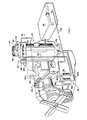
- the present invention basically includes an assembly for atomizing liquid fuel into particulate droplets and entraining such droplets in a moving stream of ambient air, indicated generally at 22 in Figures 1 and 2, and an arrangement disposed intermediate the atomizing and entraining assembly 22 and the engine 20 in communication with both thereof for receiving the fuel entrained airstream from the atomizing and entraining assembly 22, removing from the airstream fuel droplets of a size too large for substantially quick and complete combustion in the engine 20, and then directing the fuel entrained airstream to the engine 20, such arrangement being generally indicated at 24 in Figures 1 and 2.
- a fuel supplying arrangement 26 is operably associated with the fuel atomizing and entraining assembly 22 and the airstream receiving and directing arrangement 24 to provide fuel thereto as required, this arrangement 26 including a fuel tank 28, an appropriate tubular conduit 30 communicating between the tank 28 and the fuel atomizing and entraining assembly 22, and a conventional fuel pump 32, the particular construction of which is not critical and forms no part of the present invention, operatively associated with the conduit 30 for positively conveying fuel therethrough from the tank 28 to the atomizing and entraining assembly 22.
- the atomizing and entraining assembly 22 communicates with ambient air and is arranged in association with the engine 20 such that the combustion of the fuel and air mixture in the combustion chamber or chambers of the engine 20 and the exhaustion of the products of such combustion therefrom create a partial vacuum in the arrangement 24 and the assembly 22 effective to draw ambient air into the atomizing and entraining assembly to create the aforesaid moving airstream.
- the fuel atomizing and entraining assembly 22 is effective for atomizing liquid fuel into particulate droplets predominantly of such a sufficiently small size for quick, substantially complete combustion upon ignition thereof in the presence of an appropriate proportionate quantity of air in a combustion chamber of a conventional internal combustion engine and for mixing such atomized fuel with such an appropriate proportionate quantity of air.
- the receiving and directing arrangement 24 provides an enlarged chamber 24' through which the fuel entrained airstream passes and which is effective to separate therefrom the fuel droplets therein larger than the desired sufficiently small size. It is believed that, for substantially all conventional, mass-produced, gasoline-burning automobile engines, particulate droplets of approximately a diameter equal to or less than five thousandths of an inch (.005"), or one hundred twenty-seven (127) microns, would sufficiently quickly and completely combust in an engine of such type.
- the fuel atomizing and entraining assembly 22 is illustrated and includes a rectangular polyhedral block 34 adapted to be mounted on the receiving and directing arrangement 24 by a threaded collar 35 provided in the bottom surface of the block 34. Extending vertically through the block 34 from its upwardly facing surface are a plurality of cylindrical bores 36 in each of which is tightly slidably fitted an insert 38 having a central circular opening 40 taperingly converging from each end thereof to a central location of reduced cross-sectional area.
- each insert 38 communicates with the ambient atmosphere through a cap member 42 and a conventional air filter assembly 44, both mounted on the block 34, whereby the openings 40 form a plurality of venturi passageways capable of creating a respective plurality of acceleratively moving streams of ambient air when the aforesaid vacuum draw of the engine 20 is applied through the openings 40.
- the bores 36 are preferably spaced along the length of the block in pairs forming two rows and a fuel supply conduit 48 is formed longitudinally through the block 34 adjacent each row of bores 36 and communicates therewith through secondary conduits 48' each of which extends vertically from its respective conduit 48 and opens horizontally into a respective one of the bores 36.
- the inserts 38 are annularly profiled at the respective exterior locations thereon positioned adjacent the opening of the secondary conduits 48' into the bores 36 to define a circular fuel conduit 50 between each insert 38 and the wall of its bore 36 in open communication with the respective secondary conduit 48' and conduit 48 with which each bore 36 is associated.
- Each insert 38 is additionally provided with a plurality of apertures 52 spaced annularly thereabout and extending radially therethrough from the annular profile thereof forming its circular conduit 50 to a location opening into the central passageway 40 thereof immediately downstream of the location of the reduced cross-sectional area of the passageway 40.
- Annular gasket rings 54 are provided exteriorly about each insert 38 on opposite sides of its exterior profiled section to seal the circular conduit 50 formed thereby.
- a valve arrangement is operatively associated with the bores 36 for opening and closing their respective venturi passageways to communication with the plenum 70 in a predetermined sequence in relation to increases and decreases, respectively, in the partial vacuum drawn on the plenum 70 effected by the partial vacuum in the engine 20.
- a butterfly valve 80 is pivotally mounted on a horizontal axis in the lower end of each bore 36 at the location of communication thereof with the plenum 70, the butterfly valves 80 of each pair of bores 36 being rigidly mounted co-axially for associated pivotal movement, and a linkage mechanism 82 is provided on one exterior side of the block 34 in operative association with the respective axes of the butterfly valves 80 for operating the pivotal opening and closing movements thereof.
- a diaphragm-operated vacuum sensing arrangement is provided for sensing changes in the partial vacuum in the plenum 70 and is operatively connected with the linkage mechanism 82 to control the operation thereof, the sensing arrangement 86 -including a flexible diaphragm member adapted for contraction and expansion in relation to the application of vacuum suction thereto and communicating with the plenum 70 through a tubular conduit 88 for application of the partial vacuum therein to the diaphragm member.
- each of the venturi passageways is also constructed to have a substantially smaller cross-sectional area at its location of reduced cross-sectional area and relatively smaller apertures 52 than is provided by conventional apparatus.
- venturi passageways of the atomizing and entraining assembly 22 are effective to cause the ambient airstreams drawn therethrough to accelerate to velocities significantly greater than are created in conventional apparatus and to aspirate from the apertures 52 particulate fuel droplets considerably smaller than are provided by conventional apparatus and accordingly are operative to provide a fuel entrained airstream composed predominately of fuel droplets of the aforesaid sufficiently small size.
- a butterfly valve 106 is provided in the conduit 130 between the receiving and directing arrangement 24 and the intake manifold 20' of the engine 20 immediately upstream of the location at the intake manifold 20' at which an idle conduit 76 communicates with the intake manifold 20' and is operatively associated with the accelerator pedal 108 of the engine 20 for closing of the butterfly valve 106 when the accelerator pedal 108 is not depressed and for opening of the butterfly valve 106 in response and relation to the depression of the accelerator pedal 108.
- another butterfly valve 110 is provided in the cap 42 on the block 34 and is operably associated with a diaphragm-operated vacuum sensor 112 of a generally similar type to that of sensor 86 communicating through a tubular conduit 114 with the intake manifold 20' of the engine 20.
- the receiving and directing arrangement 24 includes an enlarged chamber 24' of significantly greater volumetric area than the venturi passageways and the plenum 70 of the atomizing and entraining assembly 22 for reducing the velocity of the fuel entrained airstream from the atomizing and entraining assembly 22 to allow fuel droplets larger than the aforesaid small size to gravitationally separate from the airstream and to collect in the chamber while the small fuel droplets remain entrained in the airstream for direction to the engine 20 for efficient and substantially complete combustion therein.
- the enlarged chamber 24' is defined by a housing 160 arranged to define a plurality of airstream flow paths communicating for flow successively therethrough and then to the engine 20 of the airstream from the atomizing and entraining assembly 22.
- the housing 160 is formed as a cylinder with a substantially greater diameter than axial height and is provided with a plurality of circular, concentric interior walls 162 radially spaced from the center of the housing 160 and axially extending the height of the housing 160 to form the aforesaid plurality of flow paths.
- a transverse end wall 164 extends in each flow path the radial width and axial height thereof to form a partition marking the beginning and ending locations of each flow path.
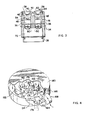
- the housing 160 is preferably arranged diametrically horizontal to cause the airstream from the atomizing and entraining assembly 22 to flow substantially horizontally, an intake port 166 opening to an intake fube 168 being provided in the outer cylindrical surface of the housing 160 adjacent one side of the end wall 164 of the radially outermost flow path for directing the airstream from the atomizing and entraining assembly 22 into such outermost flow path for flow therethrough in a counterclockwise direction as viewed in Figure 4 and, to facilitate continued counterclockwise flow of the airstream successively radially inwardly through the remaining flow paths of the housing 160, the end walls 164 of the remaining flow paths are slightly staggered progressively clockwise from the end wall 164 of the outermost flow path radially inwardly to the end wall 164 of the innermost flow path and a baffle and port arrangement is located in each flow path intermediate the end wall 164 thereof and the wall 164 of the next succeeding, radially inward flow path.
- the inwardmost interior wall 162 defines an exhaust port 170 communicating through a pipe (not shown) or other appropriate means with the intake manifold 20' of the engine 20, the baffle and port arrangement in the inwardmost wall 162 directing the airstream into such exhaust port 170.
- Each baffle and port arrangement includes a horizontal baffle member 172 disposed substantially equidistantly of the axial height of its respective flow path and extending the width of the flow path clockwise from the end wall 164 of the flow path to adjacent the location in the next succeeding, radially-inward flow path of its end wall 164.
- a port 174 is provided in each interior wall 162 forming the radially-inward wall of each flow path above the respective baffle member 172 thereof to provide communication with the next succeeding, radially inward flow path.
- the chamber receives the fuel entrained airstream of the atomizing and entraining assembly 22 through the intake port 166 and directs it counterclockwise along the radially outwardmost flow path, over the baffle member 172 thereof and through the port 174 thereof into the next succeeding, radially-inward flow path along which the airstream flows counterclockwise, the airstream flow progressing in this manner radially inwardly through the housing 160 successively along the plurality of flow paths thereof.
- the housing 160 is dimensionally constructed such that the cross-sectional area of each flow path is greater than the cross-sectional area of the intake tube 168 between the atomizing and entraining assembly 22 and the housing 160 and the total volume of the flow paths is greater than that of the airstream flow path through the atomizing and entraining assembly 22 whereby the fuel entrained airstream is reduced in velocity and volumetrically expanded through its flow through the housing 160 to cause the large droplets therein to gravitate downwardly in the airstream during its flow through the housing 160.
- a collection funnel 176 is provided in the lower cover member of the housing 160 beneath each baffle member 172 for collection of the larger droplets conveyed beneath the baffle member 172 in the above-described manner.
- an arrangement for recycling through the atomizing and entraining assembly 22 of the large fuel droplets separated and collected in the housing of the enlarged chamber.
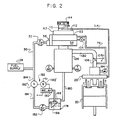
- the recycling arrangement includes a collection sub-chamber 178 ( Figure 2) which is constructed in the generally conventional manner of an ordinary float bowl and communicates through a tubular conduit 180 with the funnel or other collection member (not shown in Figure 2) of the housing of the receiving and directing arrangement 24 for gravitational flow from the collection funnel to the sub-chamber 178 of the separated large fuel droplets.
- the collected fuel is transiently stored in the sub-chamber 178 for recycling, the sub-chamber 178 being operatively associated in a manner to be described with a supplemental fuel pump 182 of conventional construction for conveyance of the collected fuel in the sub-chamber 178 through a tubular conduit 184 to either return the fuel to the supply tank 28 or to convey it into conduit 30 to again be pumped to the atomizing and entraining assembly 22.
- the sub-chamber 178 has a float member 186 pivotally mounted therein on one vertical side wall thereof for pivotal movement in floating disposition at the upper level of the collected fuel contained in the sub-chamber 178.
- a conventional mercury position switch 188 is mounted on the upper surface of the float .member 186 for sensing pivotal movement of the float member 186 caused by changes in the level of fuel in the sub-chamber 178, the switch 188 being operatively electrically associated in a conventional manner with a conventional electric relay 190 and a conventional solenoid-operated valve arrangement 192 for actuating and deactuating the relay 190 and the solenoid-operated valve arrangement 192 in response to sensed pivotal movements of the float member 186 such that the upward pivotal movement of the float member 186 effected by an increase in the level of fuel contained in the sub-chamber 178 will actuate the relay 190 to in turn energize a solenoid 192' and open a valve 192" in the conduit 184 thereby to permit the pump 182 to convey some of the contained fuel from the sub-chamber 178 and downward pivotal movement of the float member 186 upon removal of a sufficient quantity of the contained fuel from the sub-chamber 178 deactuates
- the fuel supply arrangement 26 and the atomizing and entraining assembly 22 are cooperatively arranged to feed to and entrain in the airstream an oversupply of fuel droplets sufficient to provide a predetermined proportionate quantity of small fuel droplets in the airstream.
- Additional pressure relief valves such as relief valve 194 at the intake manifold 20' of the engine 20, may also be provided to permit the release of excessive internal pressure in the atomizing and entraining assembly 22 and in the receiving and directing arrangement 24 and may be of any appropriate conventional construction.
Landscapes
- Engineering & Computer Science (AREA)
- Chemical & Material Sciences (AREA)
- Combustion & Propulsion (AREA)
- Mechanical Engineering (AREA)
- General Engineering & Computer Science (AREA)
- Combustion Methods Of Internal-Combustion Engines (AREA)
- Fuel-Injection Apparatus (AREA)
- Output Control And Ontrol Of Special Type Engine (AREA)
- Physical Or Chemical Processes And Apparatus (AREA)
Applications Claiming Priority (2)
| Application Number | Priority Date | Filing Date | Title |
|---|---|---|---|
| US06/287,078 US4510914A (en) | 1981-07-27 | 1981-07-27 | Apparatus and method for preparing a mixture of combustible liquid fuel and air |
| US287078 | 1981-07-27 |
Publications (3)
| Publication Number | Publication Date |
|---|---|
| EP0083653A1 EP0083653A1 (en) | 1983-07-20 |
| EP0083653A4 EP0083653A4 (en) | 1984-09-19 |
| EP0083653B1 true EP0083653B1 (en) | 1988-02-03 |
Family
ID=23101356
Family Applications (1)
| Application Number | Title | Priority Date | Filing Date |
|---|---|---|---|
| EP82902601A Expired EP0083653B1 (en) | 1981-07-27 | 1982-07-22 | Apparatus for preparing a mixture of combustible liquid fuel and air |
Country Status (7)
| Country | Link |
|---|---|
| US (1) | US4510914A (enExample) |
| EP (1) | EP0083653B1 (enExample) |
| JP (2) | JPS58500006U (enExample) |
| AU (1) | AU8821582A (enExample) |
| CA (1) | CA1197152A (enExample) |
| DE (2) | DE3278085D1 (enExample) |
| WO (1) | WO1983000361A1 (enExample) |
Families Citing this family (10)
| Publication number | Priority date | Publication date | Assignee | Title |
|---|---|---|---|---|
| US5992354A (en) * | 1993-07-02 | 1999-11-30 | Massachusetts Institute Of Technology | Combustion of nanopartitioned fuel |
| AUPM967894A0 (en) * | 1994-11-25 | 1994-12-22 | Hearn, Graeme George | Fuel vapourisation apparatus |
| DE19734493C1 (de) * | 1997-08-08 | 1998-11-19 | Daimler Benz Ag | Kraftstoffversorgungsanlage für eine Brennkraftmaschine |
| US8110259B2 (en) | 2004-04-02 | 2012-02-07 | Curwood, Inc. | Packaging articles, films and methods that promote or preserve the desirable color of meat |
| US7867531B2 (en) | 2005-04-04 | 2011-01-11 | Curwood, Inc. | Myoglobin blooming agent containing shrink films, packages and methods for packaging |
| US8029893B2 (en) | 2004-04-02 | 2011-10-04 | Curwood, Inc. | Myoglobin blooming agent, films, packages and methods for packaging |
| US8470417B2 (en) | 2004-04-02 | 2013-06-25 | Curwood, Inc. | Packaging inserts with myoglobin blooming agents, packages and methods for packaging |
| US8741402B2 (en) * | 2004-04-02 | 2014-06-03 | Curwood, Inc. | Webs with synergists that promote or preserve the desirable color of meat |
| US8545950B2 (en) * | 2004-04-02 | 2013-10-01 | Curwood, Inc. | Method for distributing a myoglobin-containing food product |
| US9865419B2 (en) * | 2015-06-12 | 2018-01-09 | Te Connectivity Corporation | Pressure-controlled electrical relay device |
Family Cites Families (36)
| Publication number | Priority date | Publication date | Assignee | Title |
|---|---|---|---|---|
| DE438098C (de) * | 1926-12-07 | Edward Dodson | Einrichtung zur Zufuehrung fluessigen Brennstoffs fuer Motoren mit innerer Verbrennung unter Abscheidung der groben Fluessigkeitsteilchen aus dem Gemischstrom und Wieder-zerstaeubung dieser Teilchen | |
| US871320A (en) * | 1903-08-03 | 1907-11-19 | Leon Bollee | Carbureter. |
| US1277705A (en) * | 1916-04-28 | 1918-09-03 | Thomas John Disturnal | Carbureter. |
| GB112962A (en) * | 1916-11-28 | 1918-01-28 | Alfred William Southey | Improvements in Carburetters for Internal Combustion Engines. |
| US1368178A (en) * | 1917-09-25 | 1921-02-08 | Lorraine Des Anciens Ets Lisse | Carbureter for motor-cars |
| US1479381A (en) * | 1918-05-01 | 1924-01-01 | Good Inventions Co | Liquid-fuel vaporizer |
| DE410739C (de) * | 1921-01-12 | 1925-03-13 | Brev Ughemar Soc Acc L Corsi E | Viertakt-Verbrennungskraftmaschine mit einem Zufuehrungsventil fuer brenn-stoffreiches Gemisch und einem weiteren Zufuehrungsventil fuer Zusatzluft |
| US1552995A (en) * | 1921-12-15 | 1925-09-08 | Standard Dev Co | Antiknock carburetor |
| FR578108A (fr) * | 1923-03-16 | 1924-09-18 | Carburateur à dosage d'air variable | |
| GB230165A (en) * | 1923-12-04 | 1925-03-04 | Edward Dodson | Improved method of and means for collecting and utilising unvapourised fuel in internal-combustion engines |
| US1734723A (en) * | 1924-06-13 | 1929-11-05 | Jr Richard Frederick Gildehaus | Vaporizer and fuelizer for internal-combustion engines |
| US1736239A (en) * | 1926-06-24 | 1929-11-19 | Sidney A Wilson | Multiple carburetor |
| NL30068C (enExample) * | 1932-05-25 | |||
| DE637345C (de) * | 1933-10-04 | 1936-10-26 | Sarl Sphinx | Registervergaser |
| US2083752A (en) * | 1934-02-23 | 1937-06-15 | Homer A Trussell | Fuel reclaiming system for combustion engines |
| US2098391A (en) * | 1936-01-02 | 1937-11-09 | Ward M Irvin | Gasoline saver |
| GB729422A (en) * | 1949-07-28 | 1955-05-04 | Gen Motors Corp | Improved dual carburettor apparatus for internal combustion engines |
| FR1088138A (fr) * | 1952-11-27 | 1955-03-03 | Dispositif séparateur | |
| US2823760A (en) * | 1955-05-10 | 1958-02-18 | Garrett Corp | Water separator |
| US3013778A (en) * | 1959-05-27 | 1961-12-19 | Acf Ind Inc | Multi-barrel carburetor |
| US3057335A (en) * | 1960-04-11 | 1962-10-09 | Osborne Associates | Preinduction means and method for treating a fuel air mixture |
| US3030819A (en) * | 1960-09-22 | 1962-04-24 | Edelbrock Equip | Linkage for multiple carburetor installation |
| DE1576580A1 (de) * | 1967-10-20 | 1970-07-30 | Gerhard Jankowsky | Vorrichtung fuer die Brennstoffzufuhr zu Brennkraftmaschinen |
| US3618577A (en) * | 1968-04-11 | 1971-11-09 | Continental Motors Corp | Separator for fuel-air induction system |
| US3554174A (en) * | 1969-07-07 | 1971-01-12 | Dynatech Corp | Dual circuit induction system |
| BE794384A (fr) * | 1972-01-27 | 1973-05-16 | Malherbe Alfred A | Procede et installation pour l'alimentation d'un moteur a combustion interne |
| US3851634A (en) * | 1973-06-20 | 1974-12-03 | V Everett | Fuel induction system for internal combustion engine |
| DE2341315A1 (de) * | 1973-08-16 | 1975-02-27 | Werner Rappolt | Kondensat-aufbereiter zur verbesserung der verbrennung in vergaser-motoren |
| CA951200A (en) * | 1974-01-22 | 1974-07-16 | Istvan Furucz | Systeme de carburation pour moteur a combustion interne |
| US3996907A (en) * | 1974-08-20 | 1976-12-14 | Ethyl Corporation | Fuel induction system |
| US4072139A (en) * | 1974-05-24 | 1978-02-07 | Kuniaki Miyazawa | Carburetor |
| US4086892A (en) * | 1974-09-23 | 1978-05-02 | Ethyl Corporation | Fuel induction system |
| US4020811A (en) * | 1974-11-18 | 1977-05-03 | Ventur-E, Inc. Of Richmond | Recirculating fuel feed and vaporization apparatus and method |
| US4132207A (en) * | 1976-05-28 | 1979-01-02 | Pettengill Ned H | Vehicle fuel injection system |
| US4212274A (en) * | 1977-01-21 | 1980-07-15 | Quick Thomas E | Pollution emission control and fuel saving device for internal combustion engines |
| GB1577545A (en) * | 1977-07-27 | 1980-10-22 | Beecham Group Ltd | Treatment of swine dysenter |
-
1981
- 1981-07-27 US US06/287,078 patent/US4510914A/en not_active Expired - Lifetime
-
1982
- 1982-07-22 WO PCT/US1982/000992 patent/WO1983000361A1/en not_active Ceased
- 1982-07-22 JP JP1983600005U patent/JPS58500006U/ja active Pending
- 1982-07-22 DE DE8282902601T patent/DE3278085D1/de not_active Expired
- 1982-07-22 AU AU88215/82A patent/AU8821582A/en not_active Abandoned
- 1982-07-22 DE DE19828237038U patent/DE8237038U1/de not_active Expired
- 1982-07-22 EP EP82902601A patent/EP0083653B1/en not_active Expired
- 1982-07-26 CA CA000408054A patent/CA1197152A/en not_active Expired
-
1983
- 1983-10-13 JP JP58191650A patent/JPS5990759A/ja active Pending
Also Published As
| Publication number | Publication date |
|---|---|
| WO1983000361A1 (en) | 1983-02-03 |
| EP0083653A4 (en) | 1984-09-19 |
| DE8237038U1 (de) | 1983-09-22 |
| JPS58500006U (enExample) | 1983-08-04 |
| CA1197152A (en) | 1985-11-26 |
| DE3278085D1 (en) | 1988-03-10 |
| US4510914A (en) | 1985-04-16 |
| AU8821582A (en) | 1983-03-17 |
| EP0083653A1 (en) | 1983-07-20 |
| JPS5990759A (ja) | 1984-05-25 |
Similar Documents
| Publication | Publication Date | Title |
|---|---|---|
| CN101230792B (zh) | 具有流量调节文丘里喷嘴的发动机曲轴箱强制通风系统 | |
| AU691323B2 (en) | Combination in-line air-filter/air-oil separator/air-silencer with preseparator | |
| EP0083653B1 (en) | Apparatus for preparing a mixture of combustible liquid fuel and air | |
| US4370970A (en) | Apparatus for supplying a fuel/air mixture to an internal combustion engine | |
| US3395899A (en) | Carburetor | |
| US3875916A (en) | Pollution control system for internal combustion engines | |
| US3332231A (en) | Aspirator for use in a flowing gas stream | |
| EP0052650A1 (en) | Vaporous gasoline aspiration system and fuming tank | |
| US3990420A (en) | Air induction valve | |
| CN107587913A (zh) | 用于发动机的曲轴箱通风阀 | |
| US3494339A (en) | Self-cleaning smog control filter and fire trap for internal combustion engines | |
| US3990421A (en) | Anti-pollution structure with a fuel economizing fuel feed and exhaust system for an internal combustion engine | |
| US3701513A (en) | Fuel feeding apparatus | |
| US3416503A (en) | Engine fume discharge reduction systems | |
| US4343282A (en) | Liquid tower carburetor | |
| US4256044A (en) | Air-fuel mixing device | |
| US3814391A (en) | Vehicle fuel injector | |
| US4204504A (en) | Fuel heating, air metering valve unit for engine air inlet system | |
| US3618577A (en) | Separator for fuel-air induction system | |
| US4500476A (en) | Variable venturi type carburetor | |
| US4063540A (en) | Method and apparatus for fuel recovery in internal combustion engines | |
| US3559963A (en) | Atomization and fuel cutoff carburetor | |
| US5076243A (en) | Fuel supply system for an internal combustion engine | |
| US3475011A (en) | Individual intake port carburetion system | |
| US4335060A (en) | Multi-fuel vapor charge carburetion system and device therefor |
Legal Events
| Date | Code | Title | Description |
|---|---|---|---|
| PUAI | Public reference made under article 153(3) epc to a published international application that has entered the european phase |
Free format text: ORIGINAL CODE: 0009012 |
|
| AK | Designated contracting states |
Designated state(s): DE FR GB SE |
|
| 17P | Request for examination filed |
Effective date: 19830728 |
|
| GRAA | (expected) grant |
Free format text: ORIGINAL CODE: 0009210 |
|
| AK | Designated contracting states |
Kind code of ref document: B1 Designated state(s): DE FR GB SE |
|
| PG25 | Lapsed in a contracting state [announced via postgrant information from national office to epo] |
Ref country code: FR Free format text: THE PATENT HAS BEEN ANNULLED BY A DECISION OF A NATIONAL AUTHORITY Effective date: 19880203 |
|
| PG25 | Lapsed in a contracting state [announced via postgrant information from national office to epo] |
Ref country code: SE Effective date: 19880229 |
|
| REF | Corresponds to: |
Ref document number: 3278085 Country of ref document: DE Date of ref document: 19880310 |
|
| EN | Fr: translation not filed | ||
| PG25 | Lapsed in a contracting state [announced via postgrant information from national office to epo] |
Ref country code: GB Effective date: 19880722 |
|
| PLBE | No opposition filed within time limit |
Free format text: ORIGINAL CODE: 0009261 |
|
| 26N | No opposition filed | ||
| GBPC | Gb: european patent ceased through non-payment of renewal fee | ||
| PGFP | Annual fee paid to national office [announced via postgrant information from national office to epo] |
Ref country code: DE Payment date: 19890906 Year of fee payment: 8 |
|
| PG25 | Lapsed in a contracting state [announced via postgrant information from national office to epo] |
Ref country code: DE Effective date: 19910403 |