EP0083401A2 - Druckkopf mit Nadelmatrix - Google Patents
Druckkopf mit Nadelmatrix Download PDFInfo
- Publication number
- EP0083401A2 EP0083401A2 EP82109983A EP82109983A EP0083401A2 EP 0083401 A2 EP0083401 A2 EP 0083401A2 EP 82109983 A EP82109983 A EP 82109983A EP 82109983 A EP82109983 A EP 82109983A EP 0083401 A2 EP0083401 A2 EP 0083401A2
- Authority
- EP
- European Patent Office
- Prior art keywords
- armatures
- posts
- print head
- frame
- nose piece
- Prior art date
- Legal status (The legal status is an assumption and is not a legal conclusion. Google has not performed a legal analysis and makes no representation as to the accuracy of the status listed.)
- Withdrawn
Links
Images
Classifications
-
- B—PERFORMING OPERATIONS; TRANSPORTING
- B41—PRINTING; LINING MACHINES; TYPEWRITERS; STAMPS
- B41J—TYPEWRITERS; SELECTIVE PRINTING MECHANISMS, i.e. MECHANISMS PRINTING OTHERWISE THAN FROM A FORME; CORRECTION OF TYPOGRAPHICAL ERRORS
- B41J2/00—Typewriters or selective printing mechanisms characterised by the printing or marking process for which they are designed
- B41J2/22—Typewriters or selective printing mechanisms characterised by the printing or marking process for which they are designed characterised by selective application of impact or pressure on a printing material or impression-transfer material
- B41J2/23—Typewriters or selective printing mechanisms characterised by the printing or marking process for which they are designed characterised by selective application of impact or pressure on a printing material or impression-transfer material using print wires
- B41J2/27—Actuators for print wires
- B41J2/275—Actuators for print wires of clapper type
Definitions
- the present invention relates to print heads and particularly to impact dot matrix print heads of the ballistic type.
- the invention is especially suitable for providing a print head which may be useful generally in various different designs of dot matrix printers.
- the print head is also applicable to printers which are uniquely designed to incorporate it as a part thereof.
- a dot matrix print head of the ballistic type which embodies the invention uses a plurality of print wires and has a body containing a nose piece and a coil frame assembly with a plurality of solenoidal coils and armatures.
- the print wires are disposed in the nose piece and present opposite ends for dot printing and for impact by the armatures to be ballistically driven to dot printing position.
- Guidance and mounting of the armatures for movement from a return position into impact delivering relationship with the print wires is obtained by spring means which bias the armatures toward the frame and pivotally mount one end of the armatures on the frame.
- the support structure for the spring means on the frame has a plurality of guide posts disposed in the direction of movement of the armatures.
- the posts pass through holes in the spring means and in the armatures.
- the holes have sufficient clearance to enable low friction movement of the armatures back and forth to the return position while maintaining the armatures in alignment with the posts and thereby with the frame, the solenoidal coils and the ends of the print wires on which the armatures impact.
- the construction of the nose piece and the assembly of the support and guidance means for the armatures enables them to be integrated into a compact structure which can be assembled at low cost.
- a print head 10 without the carriage block of the printer on which it is mounted.
- This carriage block is carried by the guideshaft and print head drive mechanism of the printer, also not shown, which may be conventional.
- the print head may be adapted for use in various printer mechanisms.
- the printer also includes electronic circuits, not shown, for applying current to the head to enable it to print on paper, usually computer forms, by impacting a ribbon against the paper.
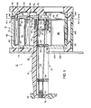
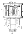
- the head 10 has a body 12 constituted of a nose piece 14 and a coil frame assembly 16.
- the nose piece 14 like many of the parts of the head 10 are molded of plastic material, preferably a polycarbonate and tetra- flourethylene (Teflon) resin is used. All of the plastic parts of the head 10 may be molded of plastic using the same resin. The polycarbonate and teflon resin may be of the type that is commercially available.
- the nose piece has a front section 18 and a rear section 20. Slotted horizontally extending flanges 22 and 24 (FIG. 3) on the front section 18 are used to connect the head to the carriage block (not shown) on the printer for traversing the head to print lines of characters on the paper as explained above.
- the bottom of the nose piece 14 may be open in order to enable the assembly of guides 24 and 26 therein and to facilitate cooling of print wires 28, seven of which are located in the nose piece 14 of the head 10.
- Head 10 is designed to print characters by a five by seven matrix (seven dots in a column and five in a row). Other matrices may, of course, be used.
- a linear row of the print wires 28 extends through a slot 30 at the front end 32 of the nose piece 14.
- the wires are side by side with their peripheries in sliding relationship in the slot 30.
- the slot is approximately the same length as the sum of the diameters of the seven print wires with a slight clearance so that the print wires may move freely through the slot out of the front end 32 of the nose piece to printing position where they impact the ribbon on the paper to form columns of dots defining the printed characters. It has been found, in accordance with the invention, that the use of jewel bearings in the front end guide may be eliminated by arranging and guiding the wires through the slot 30.
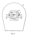
- a rectangular frame 34 with tapered ends on the top and bottom thereof serves as a ribbon guide to position the ribbon with respect to the front ends of the print wires 28.
- This guide may be attached to the front end of the flanges 22 and 24 (see FIGS. 2 and 3).
- the print wires themselves may be stainless steel (tempered 302 being suitable) . This may be material similar to that used for music or piano wire.
- the diameter may be fourteen thousanths of an inch as in conventional dot matrix print heads.
- the wires are adjacent to each other at the front end 32 of the nose piece where they contact the ribbon and paper, the printed dots are also closely adjacent to each other. This provides more continuous printing of the characters and improved printing quality.
- the nose piece also has a vertical flange 36, (see FIGS. 2 and 3). Bolts 38 extend through the flange 36 into the coil frame assembly to fixedly attach the nose piece 14 and the frame assembly 16.
- the rear section 20 of-the nose piece has an open-ended cylindrical portion 40 with diametrically opposite slots 42. Adjacent to the cylindrical portion toward the front of the nose piece is a rear guide 44 having an array of seven holes in a slight elliptical configuration about the longitudinal axis of the nose piece.
- the print wires 28 extend through these holes, which have sufficient clearance, to allow the movement of the print wires between their printing and return positions.
- the next guide 26 has a more eliptical array of holes 48.
- the wires 28 are bent toward the linear straight line array as they pass through the holes 48 in the guide 26.
- the guide 24 which is closest to the front end 32 of the nose piece 14 has holes 50 which are already in a straight line array but are spaced somewhat farther apart than the diameters of the wires 28.
- the location of the guides 24 and 26 is selected to bend the wires gradually from the circular position at the rear end of the nose piece 14 to the straight line side by side position at the front end 32 thereof.
- the intermediate guides 24 and 26 may be separately molded and press fit into the nose piece 14.
- Hookend fingers 56 which latch on the edges of the slots 42, hold the spring clip 50 in place.
- End caps 58 having collars 60 are disposed on the rear ends of the print wires 28. It is preferred that the end caps be of brass or steel. The material chosen depends upon the mass-spring characteristics of the system to maximize the transmission of forces by impact and to minimize vibration.
- the print wires are biased to return position by return springs 62 in the region 51 of the nose piece 14. The springs bear upon the end guide plate 44 and the collars 60 of the end caps 58.
- the collars 60 and clip 50 set the return position of the print wires 28.
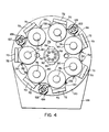
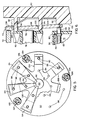
- These print wires are impacted by armatures 64 which are triangular pieces of magnetic material, suitably cold rolled steel with a nickel flashing or plating for corrosion resistance.
- the armatures are radially arranged in an array complementary to the circular array of print wires extending from the rear end of the nose piece 14. Areas adjacent to the apex of each armature on the inside surface thereof are disposed on the rear ends of the print wires 28 and their end caps 58.
- the base ends of the armatures 64 rest on the frame 66, and particularly on the end surfaces 70 of fingers 72 which extend rearwardly from the base 74 of the frame 66.
- the frame 66 itself is of magnetic material, preferably cold rolled steel, flashed or plated with nickel for corrosion resistance.
- a plurality of posts 76 equal in number to the number of print wires 28 are attached, preferably by staking them in holes in the base 74.
- the posts 76 are in a circular array complementary to the circular array of the rear ends of the print wires 28.
- These posts are also of magnetic material and may be nickel flashed or plated with the frame 66 as an assembly.
- the posts 76 form the cores or poles of the solenoidal coils 80 which actuate the armatures 64.
- the end surfaces 78 of the posts are spaced from the inside surfaces of the armatures by an air gap when the armatures are in return position. In the forward position, the inside surfaces of the armatures bear against the ends 78 of the posts 76.
- the centers of the posts 76, the centers of the end surfaces 70 of the fingers 72 and the bisectors of the triangular armatures 64 are all along radial lines through the longitudinal axis of the nose piece, which is the center of the circle along which the rear ends of the print wires 28 are arrayed.
- the print wire rear ends are also disposed along these radial lines.
- the radial lines are angularly spaced from each other by 360 0 divided by the number of print wires used in the head. In the illustrated head, which uses seven print wires, these radial lines are exactly 51° 25' and 30" apart.
- the solenoidal coils 80 are wound on bobbins 82 having end flanges 84.
- the bobbins may be of nonmagnetic material such as plastic (suitably nylon).
- the frame 66 may be considered to be the yoke of the magnetic structure with the fingers 72 and the posts 76 providing the poles for the armatures 64.
- the entire assembly 16 is considered to be the coil frame assembly, and includes the yoke 66 and the other parts which provide the means for supporting and mounting the armatures 64 about the rear section 20 of the nose piece 18.
- the support and guidance for the armature enables it to be separate and detached from the other components of the coil frame assembly, while at the same time being moveably disposed in alignment with poles 70 and 78 of the magnetic structure and the rear ends of the print wires 28.
- This supporting and guiding means is provided by a rear end cap 90, which is a disk of the same plastic material as used for the nose piece 18.
- a center post 92 extends from the inside surface of the disk.
- Two circular arrays of guide posts 94 and 96 also extend from the inside surface of the end cap 90.
- These guide posts 94 and 96 are arranged along radial lines through the axis of the end cap 90 which are angularly spaced complementary to the radial lines along which the bisectors of the armatures 64 and the rear ends of the print wires 28 are disposed.
- the armatures 64 have holes 98 and 100 (see especially FIG. 5) through which the posts 96 and 94 extend. The ends of these posts bear against the flanges 84 of the coil bobbins 92 so as to set the spacing between the inside surface of the end cap and the frame 66, taking into account, of course, the thickness of the armatures 64.
- the surface 102 of the center post 92 functions as a stop for the armatures 64.
- the holes 98 and 100 are large enough to permit the armatures 64 to be guided as they are moved with minimal frictional contact forces.
- Spring means in the form of a spider spring 104 serves to retain the armatures in place on the frame 66.
- the center of the spring 104 fits around the post 102 of the end cap and the center and part of the arms 106 of the spider spring 104 bear against the inside surface of the rear end cap 90.
- the spider spring 104 also has holes 108 and 110 which are arranged in circular arrays. The posts 94 and 96 extend through these holes 108 and 110 and maintain the arms 106 of the spider spring 104 in alignment with the armatures 64.
- the outer end surfaces of the arms 106 of the spider spring 104 bear against the armatures opposite to the areas of the armatures which are disposed on the end surfaces 70 of the fingers 72 of the frame 66.
- the armatures are pivotally mounted on the end surfaces 70.
- the ends of the arms 106 bear over a contact area to the inside of the pivot, that is towards the print wires 28. Accordingly, a bias force indicated in FIG. 6 as Fl is developed which tends to oppose the return spring bias force, indicated as F2.
- the force of the retaining spider spring 106 counterbalances the force of the return springs and sets the armatures in a return position close to the poles provided by the ends 78 of the solenoid coil posts 76.
- the electromagnetic actuation forces are thereby reduced. Consequently, the drive current for the coils 80 can be reduced, requiring less current and reducing heating (increasing the thermal efficiency) of the print head.
- the coil frame assembly 16 is completed through the use of a front end cap 120 which is also a disk of plastic material similar to that used for the other plastic parts of the head.
- Three posts 122 on the front end cap 120 are spaced apart so that they will fit in the spaces of the base 74 between the fingers 72 of the frame 66 (see FIG. 4).
- Similar posts 124 which are in alignment with the posts 122, extend from the inside surface of the rear end cap 90 (see FIG. 5).
- Tubes 126 which are desirably of the same plastic material as used for the end caps 90 and 120, receive the posts 122 and 124 in press fit relationship.
- the assembly of the coil frame assembly may be carried out with minimal labor by arranging the spider spring 104 and the armatures on the posts 94 and 96 and press fitting the end caps 90 and 120 together on the tubes 126 to clamp the coil frame 160 with the solenoidal coils between the end caps 90 and 92.
- a printed circuit board 128 contains connections for the leads 130 of the coils 80 to the actuating circuits.
- a connector (not shown) may be located, for example on the lower edge of the circuit board 128.
- the front end cap 120 is provided with holes 132.
- the leads 130 are brought forth through these holes and connected to the printed circuit board.
- the printed circuit board also acts as a heat sink or thermal dissipater. If desired, another metal plate or fin may be placed between the board 128 and the end cap 120 to facilitate heat dissipation.
- the thermal efficiency of the print head 10 is therefore high and the print head may operate at very high speeds, for example, in excess of 250 characters per second without generating heat to an extent significant to effect the performance thereof.
- the bolts 38 extend through the flange 36 and aligned holes in the printed circuit board 128 and front end cap 120 into tapped holes in the base 74 of the frame 66.
- the bolts 38 secure the nose piece 18 to the coil frame assembly 16.
- the invention may be summarized as follows:
Landscapes
- Impact Printers (AREA)
Applications Claiming Priority (2)
| Application Number | Priority Date | Filing Date | Title |
|---|---|---|---|
| US06/337,240 US4423969A (en) | 1982-01-06 | 1982-01-06 | Print head |
| US337240 | 1999-06-22 |
Publications (2)
| Publication Number | Publication Date |
|---|---|
| EP0083401A2 true EP0083401A2 (de) | 1983-07-13 |
| EP0083401A3 EP0083401A3 (de) | 1984-06-20 |
Family
ID=23319707
Family Applications (1)
| Application Number | Title | Priority Date | Filing Date |
|---|---|---|---|
| EP82109983A Withdrawn EP0083401A3 (de) | 1982-01-06 | 1982-10-28 | Druckkopf mit Nadelmatrix |
Country Status (3)
| Country | Link |
|---|---|
| US (1) | US4423969A (de) |
| EP (1) | EP0083401A3 (de) |
| JP (1) | JPS58122881A (de) |
Cited By (1)
| Publication number | Priority date | Publication date | Assignee | Title |
|---|---|---|---|---|
| WO1984003254A1 (en) * | 1983-02-25 | 1984-08-30 | Ncr Co | Wire matrix print head |
Families Citing this family (15)
| Publication number | Priority date | Publication date | Assignee | Title |
|---|---|---|---|---|
| JPS5970585A (ja) * | 1982-10-15 | 1984-04-21 | Hitachi Ltd | 印字ヘツド |
| IT1162961B (it) * | 1983-10-14 | 1987-04-01 | Olivetti & Co Spa | Dispositivo stampante a fili od aghi particolarmente per unita periferiche di sistemi elettronici per l'elaborazione di dati |
| IT1169133B (it) * | 1983-11-23 | 1987-05-27 | Honeywell Inf Systems | Gruppo armature per testina stampante a mosaico e relativo metodo di produzione |
| US4548521A (en) * | 1983-12-09 | 1985-10-22 | Ncr Corporation | Dot matrix print head |
| JPS60154084A (ja) * | 1984-01-25 | 1985-08-13 | Hitachi Ltd | 印字ヘツド及びその組立方法 |
| US4594010A (en) * | 1984-04-23 | 1986-06-10 | Bsr, Ltd. | Wire matrix print head |
| JPS60191440U (ja) * | 1984-05-31 | 1985-12-19 | 日本電産コパル株式会社 | 記録ヘツド |
| US4647236A (en) * | 1984-12-07 | 1987-03-03 | Citizen Watch Co., Ltd. | Print head |
| US4632580A (en) * | 1985-03-25 | 1986-12-30 | Ncr Corporation | Dot matrix print head dampening mechanism |
| US5149216A (en) * | 1985-05-16 | 1992-09-22 | Oki Electric Industry Co., Ltd. | Printer carriage assembly having thermal dissipating means |
| JPS61262163A (ja) * | 1985-05-16 | 1986-11-20 | Oki Electric Ind Co Ltd | ワイヤドットプリンタ |
| JPH058133Y2 (de) * | 1986-06-10 | 1993-03-01 | ||
| IT208061Z2 (it) * | 1986-07-25 | 1988-03-31 | Microlys Spa | Testina di stampa a matrice di punti di tipo perfezionato |
| US4755068A (en) * | 1987-01-30 | 1988-07-05 | Dh Technology, Inc. | Dot matrix print head assembly |
| IT1219403B (it) * | 1988-06-27 | 1990-05-11 | Olivetti & Co Spa | Testina di stampa ad aghi |
Family Cites Families (15)
| Publication number | Priority date | Publication date | Assignee | Title |
|---|---|---|---|---|
| US3994381A (en) | 1973-04-26 | 1976-11-30 | The Singer Company | Wire matrix print head |
| US4004673A (en) | 1974-06-25 | 1977-01-25 | The Singer Company | Wire matrix printhead having facility for enabling wirewear correction |
| US3893220A (en) | 1974-08-01 | 1975-07-08 | Gen Electric | Method of making wire matrix print head nozzle |
| US3929214A (en) | 1974-09-18 | 1975-12-30 | D & D Ass | Wire matrix ballistic impact print head |
| FR2287340A1 (fr) | 1974-10-08 | 1976-05-07 | Sagem | Perfectionnements apportes aux dispositifs ou tetes d'impression pour imprimantes ou analogues et procede de fabrication d'une telle tete d'impression |
| US4051941A (en) | 1976-06-28 | 1977-10-04 | Xerox Corporation | Matrix print head with improved armature retainer |
| US4060161A (en) | 1977-01-11 | 1977-11-29 | Ncr Corporation | Vibration dampening means for printing mechanism |
| JPS53141717A (en) | 1977-05-13 | 1978-12-09 | Suwa Seikosha Kk | Dot printer head structure |
| JPS5835474B2 (ja) | 1977-05-26 | 1983-08-02 | エプソン株式会社 | ワイヤ式ドツトプリンタヘツドの構造 |
| US4140406A (en) | 1977-06-13 | 1979-02-20 | Dataproducts | Dot matrix print head |
| JPS54104925A (en) | 1978-02-01 | 1979-08-17 | Suwa Seikosha Kk | Dot printer head |
| GB2022515B (en) * | 1978-05-12 | 1982-04-21 | Suwa Seikosha Kk | Head for a dot printer |
| US4240756A (en) | 1978-07-26 | 1980-12-23 | Ku Joseph P | Optimized wire matrix impact print head |
| US4279518A (en) | 1979-05-14 | 1981-07-21 | Blomquist James E | Dot matrix print head |
| DE2927385C2 (de) * | 1979-07-04 | 1986-01-16 | Mannesmann AG, 4000 Düsseldorf | Klappanker-Druckkopf für einen Nadeldrucker |
-
1982
- 1982-01-06 US US06/337,240 patent/US4423969A/en not_active Expired - Fee Related
- 1982-10-28 EP EP82109983A patent/EP0083401A3/de not_active Withdrawn
-
1983
- 1983-01-06 JP JP58000748A patent/JPS58122881A/ja active Pending
Cited By (1)
| Publication number | Priority date | Publication date | Assignee | Title |
|---|---|---|---|---|
| WO1984003254A1 (en) * | 1983-02-25 | 1984-08-30 | Ncr Co | Wire matrix print head |
Also Published As
| Publication number | Publication date |
|---|---|
| JPS58122881A (ja) | 1983-07-21 |
| EP0083401A3 (de) | 1984-06-20 |
| US4423969A (en) | 1984-01-03 |
Similar Documents
| Publication | Publication Date | Title |
|---|---|---|
| US4423969A (en) | Print head | |
| US4165940A (en) | Free flight head assembly for dot matrix printers and the like | |
| US3802543A (en) | Jewel bearings for printer heads and the like | |
| US4279521A (en) | Wire matrix print head | |
| KR100628665B1 (ko) | 단일 전기자 조립체를 갖는 도트 매트릭스 인쇄 헤드와 그 작동 방법 | |
| JPS6344551B2 (de) | ||
| EP0274117B1 (de) | Druckkopf mit einem einteiligen Anker | |
| GB2077511A (en) | Improvements in solenoids | |
| US4772141A (en) | Dot matrix printhead pin driver and method of assembly | |
| US4236836A (en) | Dot impact printer and actuator therefor | |
| HK72995A (en) | Wire-dot impact printer | |
| US4279518A (en) | Dot matrix print head | |
| US3835975A (en) | Printer head assembly | |
| US4618276A (en) | Dot matrix print head | |
| US4401392A (en) | Dot matrix print head | |
| US4728205A (en) | Positioning of dampeners in a wire matrix print head | |
| US4575268A (en) | Dot matrix printer head | |
| JPS60500612A (ja) | ワイヤ・マトリクス・プリント・ヘッド | |
| JPH03193359A (ja) | ドツトマトリツクス印字ヘツド | |
| JPS6097865A (ja) | 印刷装置 | |
| US3882986A (en) | Jewel bearings for printer heads and the like | |
| JPS5842035B2 (ja) | ドツトプリンタ用印字ヘツド | |
| JPS6042062A (ja) | ワイヤドツトヘツド | |
| US5213423A (en) | Printer with impact dot head | |
| JPH0126346B2 (de) |
Legal Events
| Date | Code | Title | Description |
|---|---|---|---|
| PUAI | Public reference made under article 153(3) epc to a published international application that has entered the european phase |
Free format text: ORIGINAL CODE: 0009012 |
|
| AK | Designated contracting states |
Designated state(s): CH DE FR GB IT LI NL |
|
| PUAL | Search report despatched |
Free format text: ORIGINAL CODE: 0009013 |
|
| AK | Designated contracting states |
Designated state(s): CH DE FR GB IT LI NL |
|
| 17P | Request for examination filed |
Effective date: 19841206 |
|
| STAA | Information on the status of an ep patent application or granted ep patent |
Free format text: STATUS: THE APPLICATION IS DEEMED TO BE WITHDRAWN |
|
| 18D | Application deemed to be withdrawn |
Effective date: 19861007 |
|
| RIN1 | Information on inventor provided before grant (corrected) |
Inventor name: KOBRYN, RONALD J. |