EP0083058A1 - Système de frein moteur du type à détente de gaz comprimé - Google Patents
Système de frein moteur du type à détente de gaz comprimé Download PDFInfo
- Publication number
- EP0083058A1 EP0083058A1 EP82111849A EP82111849A EP0083058A1 EP 0083058 A1 EP0083058 A1 EP 0083058A1 EP 82111849 A EP82111849 A EP 82111849A EP 82111849 A EP82111849 A EP 82111849A EP 0083058 A1 EP0083058 A1 EP 0083058A1
- Authority
- EP
- European Patent Office
- Prior art keywords
- valve
- control piston
- engine
- passageway
- pin valve
- Prior art date
- Legal status (The legal status is an assumption and is not a legal conclusion. Google has not performed a legal analysis and makes no representation as to the accuracy of the status listed.)
- Granted
Links
- 230000006835 compression Effects 0.000 title claims abstract description 42
- 238000007906 compression Methods 0.000 title claims abstract description 42
- 230000000979 retarding effect Effects 0.000 title claims abstract description 14
- 230000007246 mechanism Effects 0.000 claims abstract description 61
- 239000012530 fluid Substances 0.000 claims description 35
- 230000009471 action Effects 0.000 claims description 8
- 238000002485 combustion reaction Methods 0.000 claims description 7
- 238000000034 method Methods 0.000 claims description 4
- 230000008569 process Effects 0.000 claims description 3
- 230000002829 reductive effect Effects 0.000 claims description 2
- 230000003247 decreasing effect Effects 0.000 abstract description 2
- 239000003921 oil Substances 0.000 description 13
- 230000007423 decrease Effects 0.000 description 5
- 230000009977 dual effect Effects 0.000 description 5
- 239000000446 fuel Substances 0.000 description 4
- 230000008901 benefit Effects 0.000 description 3
- 238000004891 communication Methods 0.000 description 3
- 244000304337 Cuminum cyminum Species 0.000 description 2
- 238000001816 cooling Methods 0.000 description 2
- 238000007789 sealing Methods 0.000 description 2
- 239000007787 solid Substances 0.000 description 2
- 238000013016 damping Methods 0.000 description 1
- 238000010586 diagram Methods 0.000 description 1
- 230000000694 effects Effects 0.000 description 1
- 230000008030 elimination Effects 0.000 description 1
- 238000003379 elimination reaction Methods 0.000 description 1
- 230000004048 modification Effects 0.000 description 1
- 238000012986 modification Methods 0.000 description 1
- 239000010705 motor oil Substances 0.000 description 1
- 231100000989 no adverse effect Toxicity 0.000 description 1
- 230000009467 reduction Effects 0.000 description 1
- 230000002441 reversible effect Effects 0.000 description 1
- 238000004513 sizing Methods 0.000 description 1
- 230000001960 triggered effect Effects 0.000 description 1
Images


Classifications
-
- F—MECHANICAL ENGINEERING; LIGHTING; HEATING; WEAPONS; BLASTING
- F02—COMBUSTION ENGINES; HOT-GAS OR COMBUSTION-PRODUCT ENGINE PLANTS
- F02D—CONTROLLING COMBUSTION ENGINES
- F02D13/00—Controlling the engine output power by varying inlet or exhaust valve operating characteristics, e.g. timing
- F02D13/02—Controlling the engine output power by varying inlet or exhaust valve operating characteristics, e.g. timing during engine operation
- F02D13/04—Controlling the engine output power by varying inlet or exhaust valve operating characteristics, e.g. timing during engine operation using engine as brake
-
- F—MECHANICAL ENGINEERING; LIGHTING; HEATING; WEAPONS; BLASTING
- F01—MACHINES OR ENGINES IN GENERAL; ENGINE PLANTS IN GENERAL; STEAM ENGINES
- F01L—CYCLICALLY OPERATING VALVES FOR MACHINES OR ENGINES
- F01L13/00—Modifications of valve-gear to facilitate reversing, braking, starting, changing compression ratio, or other specific operations
- F01L13/06—Modifications of valve-gear to facilitate reversing, braking, starting, changing compression ratio, or other specific operations for braking
- F01L13/065—Compression release engine retarders of the "Jacobs Manufacturing" type
Definitions
- This invention generally relates to an engine retarding system of a gas compression relief type and more particularly to a system utilizing an hydrualic reset mechanism which insures that an exhaust valve (or valves) which was opened to produce the desired engine retarding effect is closed prior to the normal opening of the exhaust valve (or valves) of an internal combustion engine.
- Engine retarders of the compression relief type are well known in the art. Such retarders are designed to convert, temporarily, an internal combustion engine of the spark ignition or compression ignition type into an air compressor so as to develop a retarding horsepower which may be a substantial portion of the operating horsepower normally developed by the engine.
- Laas U.S. Patent 3,405,699 discloses a device which unloads the hydraulic system whenever excess motion of the slave or control piston opens the exhaust valve too far, a condition which increases risk of damage to the components of the engine.
- U.S. Patent 4,271,796 discloses a pressure relief system for a compression relief engine retarder wherein a bi-stable ball relief valve and a damping mechanism rapidly drops the pressure in the hydraulic system to a predetermined low level whenever an excess pressure is sensed in the hydraulic system, thereby obviating the risk of damage to various components in the engine valve train mechanism.
- Our.Belgian Patent 879,819 granted May 5, 1980 discloses an improved timing mechanism for an engine retarder which produces an increased retarding power while increasing the time span between the beginning of the engine retarding action and the beginning of the normal opening of the exhaust valves of the engine.
- the compression relief engine retarder uses the existing engine valve train and fuel injector mechanisms to operate the exhaust valves.
- the problem with the apparatus of the patents and a pp lica- tions referred to above is that the exhaust valve or valves opened by the retarder may still be open when the normal opening of the exhaust valve is timed to commence.
- the rocker arm may impact sharply against the crosshead or valve stem and produce a loading condition which is different, and perhaps more severe, than that originally contemplated in the engine design.
- Such a loading condition may be even more severe in the case of engines equipped with dual exhaust valves where the engine retarder acts on only one valve.
- the original designed symmetrical loading of the crosshead and crosshead guide is transformed into an asymmetrical loading condition whenever one of the exhaust valves is partially open when the second exhaust valve begins to open.
- an engine retarding system of a gas compression relief type wherein during a braking mode of operation of the internal combustion engine a slave or control piston is moved from a first position, under action on one of its opposite sides of high pressure hydraulic fluid supplied from a hydraulic fluid source, to a second position in which the control piston opens the exhaust valve of said engine prior to normal exhaust valve opening which occurs at the end of the power stroke of the engine, characterized by a hydraulic reset mechanism operative a predetermined time after said control piston in its second position opens said exhaust valve for reducing the pressure differential at opposite sides of said control piston to enable return of said control piston to its first position prior to said normal exhaust valve opening.
- the hydraulic reset mechanism of the invention advantageously comprises a passageway communicating at one end with the high pressure side of the control piston and communicating at its opposite end with the low pressure side of the control piston, a pin valve mounted for coaxial movement relative to the control piston and adapted to contact the passageway at the high pressure end thereof so as to seal off the passageway, a first spring means for biasing the pin valve toward the high pressure end of the passageway, second spring means effective to bias said pin valve away from the high pressure end of said passageway while the pin valve is still in contact with said high pressure end of the passageway and being effective to move said pin valve away from the passageway a predetermined time after opening of the exhaust valve by the control piston, said predetermined time being a function of rate of pressure decay in the cylinder in which the exhaust valve is opened.
- the present invention also comprises a method of operating a compression relief engine retarder wherein the decrease in cylinder pressure resulting from the timed opening of at least one engine exhaust valve is sensed by the reset mechanism which thereupon releases the pressure in the hydraulic system so that the control or slave piston may promptly return to its rest position.
- the hydraulic fluid which actuates the control piston may be stored within the retarder mechanism or elsewhere for use during a subsequent cycle of operation.
- the hydraulic reset mechanism may be incorporated into either the control piston adjusting screw or the control piston. Storage of hydraulic fluid may be provided in the control piston adjusting screw, the control piston, in one or more of the engine retarder control valves, or in any other accumulator connected to the engine brake circuit.
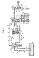
- Fig. 1 is a schematic diagram of a compression relief engine retarder adapted for use in conjunction with an internal combustion engine of the spark ignition or compression ignition type.
- the basic design of the compression relief engine retarder is disclosed in the Cummins U.S. Patent 3,220,392.
- the present invention will be described with reference to an engine retarder applied to a Cummins compression ignition engine in which the master piston of the engine retarder is driven by the injector pushrod. It will be understood that the invention may also be applied to other engines where, for example, the master piston is driven by an exhaust valve pushrod.
- the numeral 10 represents a housing fitted on an internal combustion engine within which the components of a compression relief engine retarder are contained.
- Oil 12 from a sump 14, which may be, for example, the engine crankcase, is pumped through a duct 16 by a low pressure pump 18 through a check valve 19 to the inlet 20 of a solenoid valve 22 mounted in the housing 10.
- Low pressure oil 12 is conducted from the solenoid valve 22 to a control cylinder 24 by a duct 26.
- a control valve 28, fitted for reciprocating movement within the control cylinder 24, is urged toward a closed position by a compression spring 30.
- the control valve 28 contains an inlet passage 32 closed by a ball check valve 34, which is biased into the closed position by a compression spring 36, and an outlet passage 38.
- the outlet passage 38 registers with the control cylinder outlet duct 40 which communicates with the inlet of a slave cylinder 42 also formed in the housing 10.
- the ball check valve 34 opens against the bias of spring 36 to permit the oil 12 to flow into the slave cylinder 42. From the outlet 44 of the slave cylinder 42, the oil 12 flows through a duct 46 into the master cylinder 48 formed in the housing 10.
- a slave or control piston 50 is fitted for reciprocating motion within the slave cylinder 42.
- the slave piston 50 is biased in an upward direction (as shown in Fig. 1) against an adjustable stop 52 by a compression spring 54 which is mounted within the slave cylinder 42 and acts against a bracket or snap ring 56 seated in the slave cylinder.
- the lower end of the slave piston 50 acts against a pin 51 freely journalled within a crosshead 58 which, in turn, is fitted for reciprocating motion on a guide pin 53 seated in the engine cylinder head 62.
- the pin 51 engages the stem of exhaust valve 60 while the crosshead 58 engages the stems of both exhaust valve 60 and exhaust valve 61.
- Exhaust valve springs 64 normally bias the exhaust valves 60 and 61 to the closed position as shown in Fig. l.
- a rocker arm acts downwardly upon the crosshead 58 so as to open both exhaust valves.
- the slave piston 50 acts through sliding pin 51 to open only exhaust valve 60.
- the adjustable stop 52 is set to provide a clearance of about Q.018 inch (i.e., "lash") between the slave piston 50 and sliding pin 51 when the exhaust valve 60 is closed, the slave piston 50 is seated against the adjustable stop 52, and the engine is cold. This clearance is required and is normally sufficient to accommodate expansion of the parts comprising the exhaust valve train when the engine is hot without opening the exhaust valve 60.
- a master piston 66 is fitted for reciprocating movement within the master cylinder 48 and biased in an upward direction (as viewed in Fig. 1) by a light leaf spring 68.
- the lower end of the master piston 66 contacts an adjusting screw mechanism 70 of a rocker arm 72 controlled by a pushrod 74 driven from the engine camshaft (not shown).
- the rocker arm 72 is conveniently the fuel injector rocker arm and the pushrod 74 is the injector pushrod.
- the pushrod 74 and the exhaust valve 60 are associated with the same engine cylinder.
- the valve timing is selected so that the exhaust valve 60 is opened near the end of the compression stroke of the cylinder with which the exhaust valve 60 is associated, Thus, the work done by the engine piston in compressing air during the compression stroke is released to the exhaust and cooling systems of the engine and is not xecovered during the expansion stroke of the engine.
- the solenoid valve 22 When it is desired to deactivate the compression relief retarder, the solenoid valve 22 is closed whereby the oil 12 in the control valve cylinder 24 passes through the duct 26, the solenoid -valve 22, and the return duct 76 to the sump 14. The control valve 28 will then be urged downwardly by the spring 30 and a portion of the oil in the slave cylinder 42 and master cylinder 48 will be vented over the top of the control valve 28 and returned to the sump 14 by duct means (not shown).
- the electrical control system for the engine retarder includes the vehicle battery 78 which is grounded at 80.
- the hot terminal of the battery 78 is connected, in series, to a fuse 82, a dash switch 84, a clutch switch 86, a fuel pump switch 88, the solenoid 22 and, preferably, through a diode 90 back to ground 80.
- the switches 84, 86, and 88 are provided to assure the safe operation of the system.
- Switch 84 is a manual control to deactivate the entire system.
- Switch 86 is an automatic switch connected to the clutch to deactivate the system whenever the clutch is disengaged so as to prevent engine stalling.
- Switch 88 is a second automatic switch connected to the fuel system to prevent engine fueling when the engine retarder is in operation.
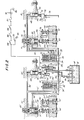
- Fig. 2 shows the control valve, master piston and cylinder, and slave piston and cylinder associated with a second cylinder of the engine in addition to the parts of the engine shown in Fig. 1.
- Fig. 2 the right-hand portion is identical to the apparatus shown in Fig. 1 and bears the same nomenclature.
- the additional components required for the second cylinder are shown at the left and are identified by primed numbers. It will be understood that the engine retarder mechanism operates at a different time for each cylinder.
- the interconnection of the control valve cylinders 24 and 24' through the ducts 26 and 26' has a particular advantage as will be pointed out in detail below.
- the hydraulic reset mechanism in accordance with the present invention may be incorporated into the slave piston 50 or the slave piston adjusting screw 52 and may, in addition, utilize the control valves 28 and 28'.
- Fig; 3 is a graph showing the movement of an exhaust valve 60 under different operating conditions.
- the curve 92 identified by the symbols "xxx" depicts the normal motion of an exhaust valve 60 when the engine is operating in the fueling mode.
- the solid curve 94 represents the motion of the exhaust valve 60 with an engine retarder of the type described hereinabove. The significant factor as may be appreciated from solid curve 94 is that the exhaust valve is open when the normal exhaust valve opening sequence begins and it is this condition that may cause the operating difficulties set forth above.
- Curve 96 shows the operation in accordance with the present invention. As shown by curve 96, the exhaust valve 60 is first opened and is thereafter closed or substantially closed (points "d" or "d' ”) just .prior to the normal exhaust valve opening sequence. As a result, the engine retarder mechanism has no adverse effect on the normal operation of the exhaust valve train mechanism.
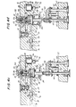
- Fig. 4(a) illustrates the engine retarder mechanism in accordance with the present invention at the beginning of a cycle of operation of the exhaust valve after the mechanical lash in the system has been taken up. This is also shown as point “a” on Fig. 3 and follows the initial or rest position of the mechanism indicated by "i" on Fig. 3.
- the hydraulic reset mechanism is contained, principally, in the slave piston adjusting screw 52.
- the adjusting screw 52 is formed with a first bore 100 which is bored partway through the adjusting screw 52 from the end which contacts the slave piston 50.
- a second narrower bore 102 extends more deeply into the adjusting screw 52.
- a bore 103, or other passageway, in the body of the adjusting screw 52 serves to equalize the pressures within and without the adjusting screw.
- the hydraulic reset mechanism comprises a reset pin valve 110 having an enlarged head 112 mounted for reciprocating movement within the adjusting screw 52.
- the pin valve 110 is biased downwardly against the slave piston 50 by a relatively light first compression spring 114 mounted between the end of the bore 102 and an axial bore 113 in the head 112 of the pin valve 110.
- the reset mechanism includes a second compression spring 104 which seats, at one end, on the shoulder 106 formed between the bores 100 and 102 and at the other end on a snap ring 108 seated in a groove formed on the inside wall of bore 100.
- a diametral hole 115 connecting with the axial bore 113 in the pin valve 110 provides a means of communication between the bores 100 and 102 so as to equalize the hydraulic pressure in bores 100 and 102.
- the pressure equalizing function of the bore 115 in conjunction with the axial bore 113 can be provided by other equivalent means. For example, as shown on Fig. 4f one or more longitudinal channels 117 on the outer periphery of the head 112 of the pin valve 110 extending from the head end to the body end of the head 112 will also perform the pressure equalizing function.
- the head 112 of the pin valve 110 and the compression spring 104 are dimensioned so that movement of the head 112 of pin valve 110 in a downward direction beyond the shoulder 106 will cause the pin valve 110 to engage and to begin to compress the spring 104 so that when hydraulic pressure begins to decay, as at point c in Fig. 3, the pin valve 110 will be disengaged from the slave or control piston 50.
- the slave piston 50 is formed with a circumferential groove 116, a diametral hole 118 communicating with the groove 116 and an axial passage or hole 120 communicating with the diametral hole 118.
- the axial hole 120 is smaller in diameter than the body portion of pin valve 110 so that when the pin valve 110 is seated against the head of the slave piston 50 the axial hole 120 is sealed.
- a duct 122 is provided in the housing 10 which communicates between the control valve cylinder 24 (and the duct 26) and the circumferential groove 116 of the slave piston.
- the holes 120 and 118, the groove 116, and the duct 122 provide a means of communication between the high pressure side of the hydraulic system comprising the master cylinder 48 above the master piston 66, the sleeve cylinder 42 above the slave piston 50, and the interconnecting ducts 40 and 46 on the one hand and the low pressure side of the hydraulic system including the duct 26 and the control valve cylinder 24 under the control valve 28.
- This means of communication is controlled as a function of the position of the reset pin valve 110 in relation to the opening in axial passageway 120.
- the slave piston 50 is positioned against the pin 51, the exhaust valve 60 is closed, the master piston 66 has just begun to move so as to take up the lash in the mechanism (point (a) in Fig. 3), and the hydraulic fluid within the high pressure side of the circuit, including the bores 100 and 102, is under relatively low pressure.
- the pin valve 110 is biased against the axial hole 120 by spring 114 and by a force proportional to the difference between the area of the body of the valve 110 and the area of the axial hole 120 times the pressure in the high pressure system.
- Fig. 3 illustrates the movement of the exhaust valve from its initial closed position (Fig. 3, point “a” and Fig. 4Ca)), to its open retarder actuated position (Fig. 3, point “b” and Fig. 4Cb)).
- the sealing force on the reset valve 110 increases with the hydraulic pressure (due in part to the action of the pressure equalizing opening 115) so that the axial hole 120 remains sealed even though the spring 104 begins to exert an upward or opening force on the reset valve 110.
- the axial hole 120 remains sealed from point “b” until point "c" at which latter point the reset valve begins to open.
- FIG. 4(c) A point at which the reset valve has opened is illustrated in Fig. 4(c) (and point “c" of Fig. 3), while the point at which the slave piston has returned to its position against the reset valve 110 is shown in Fig. 4(d) (and point “d” of Fig. 3).
- the exhaust valve is closed (point d in Fig. 3) just before normal opening of the exhaust valve.
- the reset valve may he triggered at any point after the exhaust valve 60 has begun to open and bled down the pressure within the engine cylinder.
- Fig. 4(e) shows the last step in the cycle when the master piston has begun to return to its rest position and the pressure within the retarder hydraulic circuit has an- proached its original level.
- the master piston 66 moves downward the pressure in the hydraulic circuit and thereby on the control piston 50 is reduced and the control piston 50 is then moved upward by spring 54 against the adjusting screw 52. Upward movement of the control piston 50 causes some of the hydraulic fluid stored below the control valve 28 to pass through the ball check valve 34 and then back into the high pressure circuit.
- Figs. 4(a)-4(e) it was pointed out that the hydraulic fluid which became excess for a portion of the cycle was conveniently stored under the control valve 28.
- the diameter of the control valve 28 may be smaller than the diameter of the control piston 50 so that there is insufficient volume available to store the requiresite amount of fluid.
- the arrangement shown in Fig. 2 may be employed.
- the engine retarder mechanisms for two cylinders (or, in some cases, three cylinders) may be interconnected so as to be operated by a single solenoid valve 22. This is feasible because the cylinders reach the end of their compression strokes at different times and, therefore, one retarder mechanism will be non-operating when the other retarder mechanism is required to function.
- both control valve cylinders (24 and 24') are available for storage purposes.
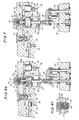
- Fig. 5 Another form of the present invention is illustrated in Fig. 5.
- the reset valve is formed within the slave piston while the adjusting screw is modified to provide a storage function.
- the slave piston 50(a) is mounted for reci p roca- tion in the slave cylinder 42 which communicates through a duct 46 with the master cylinder (not shown).
- the slave piston 50(a) is biased upwardly against the adjusting screw 52(a) by a spring or springs 54 which act against a snap ring mounted plate 55.
- Two coaxial bores 130 and 132 are formed in the slave piston 50(a) so as to define a shoulder 134 therebetween.
- a pin valve 136 is mounted for reciprocating movement within the bore 132 and lightly biased in an upward direction (as viewed in Fig. 5) by a compression spring 138.
- the pin valve 136 is provided with an axial bore 137 which communicates with a diametral bore 139.
- the bores 137 and 139 serve to equalize the hydraulic pressure in bores 130 and 132.
- Bore 137 additionally functions as a seat for spring,138.
- a second compression spring 140 is seated between the shoulder 134 and a snap ring 142 affixed in the bore 130.
- the compression spring 140 and the pin valve 136 are sized so that movement of the pin valve 136 in an upward direction will result in engagement with the second compression spring 140 and a resultant b.ias in a downward direction.
- the slave piston 50(a) is provided with a third bore 144, coaxial with bores 130 and 132, but larger than either of the latter bores.
- the base of bore 144 serves as a seat by which the slave piston 50(a) contacts the adjusting screw 52(a).
- Adjusting screw 52(a) is threaded into the housing 10 and may be locked into the desired adjustment by a lock nut 146.
- a bore 148 is formed within and partway through the adjusting screw, while the lower outer end of the adjusting screw is relieved so as to form a shallow cylindrical chamber 150.
- An orifice 152 communicates between the bore 148 and the chamber 150.
- a channel 153 formed in the base of the adjusting screw 52a communicates between chamber 150 and bore 144 in slave piston 50a.
- Pin valve 136 has a diameter which is greater than that of the orifice 152 and functions to seal orifice 152 whenever pin valve 136 and orifice 152 are in engagement.
- a piston 154 is mounted for reciprocal movement within the bore 148 of the adjusting screw 52(a) and biased in a downward direction by a compression spring 156 seated between the piston 154 and a washer 158 held within the bore 148 by a snap ring 160.
- hydraulic fluid enters the slave cylinder 42 through duct 46 and urges the slave piston 50(a) downwardly against the bias of the valve train mechanism (not shown) and compression springs 54.
- hydraulic fluid is at all times connected to bores 130 and 132 and, together with spring 138, maintains an upward bias on the pin valve 136 so as to seal the orifice 152.
- Continued downward motion of the slave piston 50(a) causes the spring 140 to engage the pin valve 136 and exert an additional force tending to open the pin valve 136 but insufficient to do so when the pressure of the hydraulic fluid is high.
- Such a condition occurs between points "a" and "b” of Fig. 3.
- the pressure decays, as shown at point "c" of Fig.
- the force of spring 140 is sufficient to snap open the pin valve 136 and the hydraulic fluid enters the adjusting screw 52(a) through the orifice 152.
- Release of the hydraulic fluid from the slave cylinder 42 reduces the pressure on slave piston 50(a) and permits piston 50(a) to return to its original position with the excess hydraulic fluid trapped in the adjusting screw 52(a).
- the spring 156 will drive the piston 154 downwardly and return the hydraulic fluid to the slave cylinder 42 through the orifice 152.
- the slave piston 50(b) has formed therein a pair of concentric bores 162 and 164.
- a piston 166 is mounted for reciprocating movement within the bore 164 and is biased in an upward direction as viewed in Fig. 6 by a compression spring 168, one end of which is seated in the bottom of the bore 162 while the other end bears against the piston 166.
- a cap 170 is threaded into the upper end of the bore 164 so as to. define, with the bore 164 and the piston 166, a storage chamber 171 for hydraulic fluid.
- a central passageway 172 formed in the cap 170 serves as a means for the ingress and egress of hydraulic fluid except when closed by the reset pin valve 110.
- the slave piston 50(b) under action of spring 54 moves in an upward direction permitting the exhaust valve 60 (Figs. 1 and 4(d)) to close (under action of spring 64) and re-engaging the reset pin valve 110.
- This return motion of the slave piston 50(b) occurs before the master piston 66 (piston 66 (Figs. 1 and 4(c) returns to its original rest position and thus the engine retarder apparatus is substantially disengaged from the valve train mechanism before the normal opening of the exhaust valve begins.
- a duct 174 is formed through the slave piston 50(c) from a point at the center of the top surface of the piston to a point on the low pressure side of the piston. It will also be appreciated that duct 122 in housing 10 may be omitted along with circumferential groove 116. Since the object of the duct 174 is simply to provide a passageway between the high pressure region above the slave piston and a region of low pressure, it will also be understood that if the duct 122 (Fig.
- the present invention provides means for closing the exhaust valves as soon as their compression relief function has been completed.
- the prompt closing of the exhaust valve reduces the valve overlap to that originally designed into the engine prior to the addition of the engine retarder, and thus more retarding work may be extracted from the ensuing expansion stroke of the engine.
- the total retarding horsepower will be increased through application of the present invention.
- valve overlap also provides another important advantage. This is that the improved compression relief retarder is more compatible with the concomitant use of an exhaust brake or a diverter valve coupled with a twin entry exhaust driven turbocharger. Either of these combinations will result in a further increase in the retarding horsepower which may be developed by the engine.
Landscapes
- Engineering & Computer Science (AREA)
- Mechanical Engineering (AREA)
- General Engineering & Computer Science (AREA)
- Chemical & Material Sciences (AREA)
- Combustion & Propulsion (AREA)
- Valve Device For Special Equipments (AREA)
- Output Control And Ontrol Of Special Type Engine (AREA)
- Vehicle Body Suspensions (AREA)
- Gas Separation By Absorption (AREA)
- Treating Waste Gases (AREA)
- Investigating Or Analysing Biological Materials (AREA)
Priority Applications (1)
| Application Number | Priority Date | Filing Date | Title |
|---|---|---|---|
| AT82111849T ATE18457T1 (de) | 1981-12-24 | 1982-12-21 | Motorbremssystem mit dekompressionseinrichtung. |
Applications Claiming Priority (2)
| Application Number | Priority Date | Filing Date | Title |
|---|---|---|---|
| US334265 | 1981-12-24 | ||
| US06/334,265 US4399787A (en) | 1981-12-24 | 1981-12-24 | Engine retarder hydraulic reset mechanism |
Publications (2)
| Publication Number | Publication Date |
|---|---|
| EP0083058A1 true EP0083058A1 (fr) | 1983-07-06 |
| EP0083058B1 EP0083058B1 (fr) | 1986-03-05 |
Family
ID=23306404
Family Applications (1)
| Application Number | Title | Priority Date | Filing Date |
|---|---|---|---|
| EP82111849A Expired EP0083058B1 (fr) | 1981-12-24 | 1982-12-21 | Système de frein moteur du type à détente de gaz comprimé |
Country Status (12)
| Country | Link |
|---|---|
| US (1) | US4399787A (fr) |
| EP (1) | EP0083058B1 (fr) |
| JP (1) | JPS58117311A (fr) |
| AT (1) | ATE18457T1 (fr) |
| AU (1) | AU543476B2 (fr) |
| BR (1) | BR8207445A (fr) |
| CA (1) | CA1213184A (fr) |
| DE (1) | DE3269756D1 (fr) |
| ES (1) | ES8404465A1 (fr) |
| IE (1) | IE53600B1 (fr) |
| IN (1) | IN157617B (fr) |
| ZA (1) | ZA829457B (fr) |
Cited By (2)
| Publication number | Priority date | Publication date | Assignee | Title |
|---|---|---|---|---|
| EP0549996A1 (fr) * | 1992-01-03 | 1993-07-07 | Jacobs Brake Technology Corporation | Valve de remise à zéro pour système de frein moteur à décompression |
| US5257605A (en) * | 1991-06-28 | 1993-11-02 | Mannesmann Rexroth Gmbh | Engine brake for a multicylinder internal combustion engine |
Families Citing this family (44)
| Publication number | Priority date | Publication date | Assignee | Title |
|---|---|---|---|---|
| US4485780A (en) * | 1983-05-05 | 1984-12-04 | The Jacobs Mfg. Company | Compression release engine retarder |
| US4475500A (en) * | 1983-12-28 | 1984-10-09 | Cummins Engine Company, Inc. | Automatic lash adjustment for engine compression brake |
| US4572114A (en) * | 1984-06-01 | 1986-02-25 | The Jacobs Manufacturing Company | Process and apparatus for compression release engine retarding producing two compression release events per cylinder per engine cycle |
| JPS61152740U (fr) * | 1985-03-15 | 1986-09-20 | ||
| US4655178A (en) * | 1985-05-08 | 1987-04-07 | Meneely Vincent A | Anti-lash adjuster |
| US4592319A (en) * | 1985-08-09 | 1986-06-03 | The Jacobs Manufacturing Company | Engine retarding method and apparatus |
| JPS6257713U (fr) * | 1985-09-30 | 1987-04-10 | ||
| US4648365A (en) * | 1985-11-26 | 1987-03-10 | Cummins Engine Company, Inc. | Engine compression braking system for an internal combustion engine |
| US4697558A (en) * | 1986-02-18 | 1987-10-06 | Meneely Vincent A | Compression relief engine brake |
| USRE33052E (en) * | 1986-06-10 | 1989-09-12 | The Jacobs Manufacturing Company | Compression release retarder with valve motion modifier |
| US4706624A (en) * | 1986-06-10 | 1987-11-17 | The Jacobs Manufacturing Company | Compression release retarder with valve motion modifier |
| US4706625A (en) * | 1986-08-15 | 1987-11-17 | The Jacobs Manufacturing Company | Engine retarder with reset auto-lash mechanism |
| US4793307A (en) * | 1987-06-11 | 1988-12-27 | The Jacobs Manufacturing Company | Rocker arm decoupler for two-cycle engine retarder |
| US4898128A (en) * | 1988-04-07 | 1990-02-06 | Meneely Vincent A | Anti-lash adjuster |
| US4996957A (en) * | 1990-06-04 | 1991-03-05 | Jacobs Brake Technology Corporation | Control valve for a compression release engine retarder |
| US5012778A (en) * | 1990-09-21 | 1991-05-07 | Jacobs Brake Technology Corporation | Externally driven compression release retarder |
| DE4102537A1 (de) * | 1991-01-29 | 1992-07-30 | Man Nutzfahrzeuge Ag | Auslass-ventilstoessel fuer eine brennkraftmaschine |
| US5161501A (en) * | 1992-01-03 | 1992-11-10 | Jacobs Brake Technology Corporation | Self-clippping slave piston |
| US5379737A (en) * | 1993-08-26 | 1995-01-10 | Jacobs Brake Technology Corporation | Electrically controlled timing adjustment for compression release engine brakes |
| US5619963A (en) * | 1994-07-29 | 1997-04-15 | Caterpillar Inc. | Dual force actuator for use in engine retarding systems |
| US5540201A (en) * | 1994-07-29 | 1996-07-30 | Caterpillar Inc. | Engine compression braking apparatus and method |
| US5647318A (en) * | 1994-07-29 | 1997-07-15 | Caterpillar Inc. | Engine compression braking apparatus and method |
| US5526784A (en) * | 1994-08-04 | 1996-06-18 | Caterpillar Inc. | Simultaneous exhaust valve opening braking system |
| US5462025A (en) * | 1994-09-28 | 1995-10-31 | Diesel Engine Retarders, Inc. | Hydraulic circuits for compression release engine brakes |
| US5460131A (en) * | 1994-09-28 | 1995-10-24 | Diesel Engine Retarders, Inc. | Compact combined lash adjuster and reset mechanism for compression release engine brakes |
| DE4440289C2 (de) * | 1994-11-11 | 1997-07-17 | Daimler Benz Ag | Motorbremsvorrichtung |
| US5511460A (en) * | 1995-01-25 | 1996-04-30 | Diesel Engine Retarders, Inc. | Stroke limiter for hydraulic actuator pistons in compression release engine brakes |
| US5996550A (en) * | 1997-07-14 | 1999-12-07 | Diesel Engine Retarders, Inc. | Applied lost motion for optimization of fixed timed engine brake system |
| US6095115A (en) * | 1998-02-02 | 2000-08-01 | Diesel Engine Retarders, Inc. | Self-clipping slave piston device with lash adjustment for a compression release engine retarder |
| US6718940B2 (en) | 1998-04-03 | 2004-04-13 | Diesel Engine Retarders, Inc. | Hydraulic lash adjuster with compression release brake |
| US6273057B1 (en) | 1998-08-19 | 2001-08-14 | Diesel Engine Retarders, Inc. | Hydraulically-actuated fail-safe stroke-limiting piston |
| US6234143B1 (en) | 1999-07-19 | 2001-05-22 | Mack Trucks, Inc. | Engine exhaust brake having a single valve actuation |
| EP1232336A4 (fr) | 1999-09-17 | 2009-08-05 | Diesel Engine Retarders Inc | Accumulateur a volume captif pour systeme a perte de mouvement |
| WO2001046578A1 (fr) | 1999-12-20 | 2001-06-28 | Diesel Engine Retarders, Inc. | Procede et dispositif relatifs a une fermeture hydraulique et a un reenclenchement des systemes de freinage d'un moteur, par utilisation de la perte du mouvement |
| US6253730B1 (en) | 2000-01-14 | 2001-07-03 | Cummins Engine Company, Inc. | Engine compression braking system with integral rocker lever and reset valve |
| US6446598B1 (en) * | 2000-12-11 | 2002-09-10 | Caterpillar Inc. | Compression brake actuation system and method |
| US6474296B2 (en) * | 2000-12-19 | 2002-11-05 | Caterpillar Inc. | Lash adjustment for use with an actuator |
| US6691674B2 (en) | 2001-06-13 | 2004-02-17 | Diesel Engine Retarders, Inc. | Latched reset mechanism for engine brake |
| CN1318744C (zh) * | 2004-01-03 | 2007-05-30 | 马银良 | 一种发动机缓速器 |
| JP4238151B2 (ja) * | 2004-01-30 | 2009-03-11 | 本田技研工業株式会社 | エンジンの動弁装置 |
| WO2014145544A1 (fr) * | 2013-03-15 | 2014-09-18 | Cummins Inc. | Mécanisme de réarmement d'un frein à décompression |
| US9752471B2 (en) | 2013-11-25 | 2017-09-05 | Pacbrake Company | Compression-release engine brake system for lost motion rocker arm assembly and method of operation thereof |
| CN105899770B (zh) | 2013-11-25 | 2019-06-18 | Pac制动公司 | 用于空转摇臂组件的压缩释放发动机制动系统及其操作方法 |
| KR101714124B1 (ko) * | 2014-12-09 | 2017-03-08 | 현대자동차주식회사 | 압축완화 엔진 브레이크의 초기화 장치 |
Citations (4)
| Publication number | Priority date | Publication date | Assignee | Title |
|---|---|---|---|---|
| US3405699A (en) * | 1966-06-17 | 1968-10-15 | Jacobs Mfg Co | Engine braking system with trip valve controlled piston |
| US3859970A (en) * | 1973-01-22 | 1975-01-14 | Allis Chalmers | Engine retarder brake |
| FR2440469A1 (fr) * | 1978-11-06 | 1980-05-30 | Jacobs Mfg Co | Systeme de frein moteur |
| US4271796A (en) * | 1979-06-11 | 1981-06-09 | The Jacobs Manufacturing Company | Pressure relief system for engine brake |
Family Cites Families (1)
| Publication number | Priority date | Publication date | Assignee | Title |
|---|---|---|---|---|
| US4150640A (en) * | 1977-12-20 | 1979-04-24 | Cummins Engine Company, Inc. | Fluidic exhaust valve opening system for an engine compression brake |
-
1981
- 1981-12-24 US US06/334,265 patent/US4399787A/en not_active Expired - Lifetime
-
1982
- 1982-12-21 EP EP82111849A patent/EP0083058B1/fr not_active Expired
- 1982-12-21 DE DE8282111849T patent/DE3269756D1/de not_active Expired
- 1982-12-21 AT AT82111849T patent/ATE18457T1/de not_active IP Right Cessation
- 1982-12-22 AU AU91767/82A patent/AU543476B2/en not_active Ceased
- 1982-12-22 BR BR8207445A patent/BR8207445A/pt not_active IP Right Cessation
- 1982-12-23 CA CA000418424A patent/CA1213184A/fr not_active Expired
- 1982-12-23 ZA ZA829457A patent/ZA829457B/xx unknown
- 1982-12-23 IE IE3083/82A patent/IE53600B1/en unknown
- 1982-12-24 JP JP57234923A patent/JPS58117311A/ja active Granted
- 1982-12-24 IN IN1485/CAL/82A patent/IN157617B/en unknown
- 1982-12-24 ES ES518561A patent/ES8404465A1/es not_active Expired
Patent Citations (4)
| Publication number | Priority date | Publication date | Assignee | Title |
|---|---|---|---|---|
| US3405699A (en) * | 1966-06-17 | 1968-10-15 | Jacobs Mfg Co | Engine braking system with trip valve controlled piston |
| US3859970A (en) * | 1973-01-22 | 1975-01-14 | Allis Chalmers | Engine retarder brake |
| FR2440469A1 (fr) * | 1978-11-06 | 1980-05-30 | Jacobs Mfg Co | Systeme de frein moteur |
| US4271796A (en) * | 1979-06-11 | 1981-06-09 | The Jacobs Manufacturing Company | Pressure relief system for engine brake |
Cited By (3)
| Publication number | Priority date | Publication date | Assignee | Title |
|---|---|---|---|---|
| US5257605A (en) * | 1991-06-28 | 1993-11-02 | Mannesmann Rexroth Gmbh | Engine brake for a multicylinder internal combustion engine |
| US5309881A (en) * | 1991-06-28 | 1994-05-10 | Mannesmann Rexroth Gmbh | Engine brake for a multicyclinder internal combustion engine |
| EP0549996A1 (fr) * | 1992-01-03 | 1993-07-07 | Jacobs Brake Technology Corporation | Valve de remise à zéro pour système de frein moteur à décompression |
Also Published As
| Publication number | Publication date |
|---|---|
| ES518561A0 (es) | 1984-04-16 |
| IN157617B (fr) | 1986-05-03 |
| IE823083L (en) | 1983-06-24 |
| ATE18457T1 (de) | 1986-03-15 |
| EP0083058B1 (fr) | 1986-03-05 |
| AU9176782A (en) | 1983-06-30 |
| JPH0253602B2 (fr) | 1990-11-19 |
| BR8207445A (pt) | 1983-10-18 |
| AU543476B2 (en) | 1985-04-18 |
| ZA829457B (en) | 1983-10-26 |
| JPS58117311A (ja) | 1983-07-12 |
| IE53600B1 (en) | 1988-12-21 |
| CA1213184A (fr) | 1986-10-28 |
| DE3269756D1 (en) | 1986-04-10 |
| US4399787A (en) | 1983-08-23 |
| ES8404465A1 (es) | 1984-04-16 |
Similar Documents
| Publication | Publication Date | Title |
|---|---|---|
| EP0083058B1 (fr) | Système de frein moteur du type à détente de gaz comprimé | |
| US4706625A (en) | Engine retarder with reset auto-lash mechanism | |
| US4423712A (en) | Engine retarder slave piston return mechanism | |
| US5000145A (en) | Compression release retarding system | |
| EP0249833B1 (fr) | Dispositif et méthode de freinage d'un moteur du type à relâchement de la compression | |
| US5996550A (en) | Applied lost motion for optimization of fixed timed engine brake system | |
| KR100575042B1 (ko) | 엔진 밸브 작동 시스템 | |
| US5829397A (en) | System and method for controlling the amount of lost motion between an engine valve and a valve actuation means | |
| US6691674B2 (en) | Latched reset mechanism for engine brake | |
| US7500466B2 (en) | Variable valve actuation and engine braking | |
| EP0549996B1 (fr) | Valve de remise à zéro pour système de frein moteur à décompression | |
| US5460131A (en) | Compact combined lash adjuster and reset mechanism for compression release engine brakes | |
| US4271796A (en) | Pressure relief system for engine brake | |
| EP0549997B1 (fr) | Piston récepteur à butée automatique | |
| NO862153L (no) | Fremgangsmaate og anordning til motorbremsing. | |
| US4419977A (en) | Fuel injection system and timing advance device therefor | |
| NO852203L (no) | Fremgangsmaate til motorbremsing ved kompresjonsavlastning. | |
| US4996957A (en) | Control valve for a compression release engine retarder | |
| US5215054A (en) | Valve control apparatus and method | |
| US4898206A (en) | Compression release retarder with valve motion modifier | |
| US4254749A (en) | Fuel injection system and timing advance device therefor | |
| USRE33052E (en) | Compression release retarder with valve motion modifier | |
| US4838516A (en) | Compression release retarder with valve motion modifier | |
| US4949751A (en) | Compression release retarder with valve motion modifier | |
| JP2563796Y2 (ja) | 内燃機関用油圧動弁装置 |
Legal Events
| Date | Code | Title | Description |
|---|---|---|---|
| PUAI | Public reference made under article 153(3) epc to a published international application that has entered the european phase |
Free format text: ORIGINAL CODE: 0009012 |
|
| AK | Designated contracting states |
Designated state(s): AT BE CH DE FR GB IT LI LU NL SE |
|
| 17P | Request for examination filed |
Effective date: 19831011 |
|
| RAP1 | Party data changed (applicant data changed or rights of an application transferred) |
Owner name: THE JACOBS MANUFACTURING COMPANY |
|
| ITF | It: translation for a ep patent filed | ||
| GRAA | (expected) grant |
Free format text: ORIGINAL CODE: 0009210 |
|
| AK | Designated contracting states |
Kind code of ref document: B1 Designated state(s): AT BE CH DE FR GB IT LI LU NL SE |
|
| REF | Corresponds to: |
Ref document number: 18457 Country of ref document: AT Date of ref document: 19860315 Kind code of ref document: T |
|
| REF | Corresponds to: |
Ref document number: 3269756 Country of ref document: DE Date of ref document: 19860410 |
|
| ET | Fr: translation filed | ||
| PGFP | Annual fee paid to national office [announced via postgrant information from national office to epo] |
Ref country code: AT Payment date: 19861127 Year of fee payment: 5 |
|
| PG25 | Lapsed in a contracting state [announced via postgrant information from national office to epo] |
Ref country code: LU Free format text: LAPSE BECAUSE OF NON-PAYMENT OF DUE FEES Effective date: 19861231 |
|
| PLBE | No opposition filed within time limit |
Free format text: ORIGINAL CODE: 0009261 |
|
| STAA | Information on the status of an ep patent application or granted ep patent |
Free format text: STATUS: NO OPPOSITION FILED WITHIN TIME LIMIT |
|
| 26N | No opposition filed | ||
| PGFP | Annual fee paid to national office [announced via postgrant information from national office to epo] |
Ref country code: NL Payment date: 19871231 Year of fee payment: 6 |
|
| PG25 | Lapsed in a contracting state [announced via postgrant information from national office to epo] |
Ref country code: AT Effective date: 19881221 |
|
| PG25 | Lapsed in a contracting state [announced via postgrant information from national office to epo] |
Ref country code: LI Effective date: 19881231 Ref country code: CH Effective date: 19881231 |
|
| REG | Reference to a national code |
Ref country code: CH Ref legal event code: PL |
|
| PG25 | Lapsed in a contracting state [announced via postgrant information from national office to epo] |
Ref country code: BE Effective date: 19891231 |
|
| BERE | Be: lapsed |
Owner name: THE JACOBS MFG CY Effective date: 19891231 |
|
| PG25 | Lapsed in a contracting state [announced via postgrant information from national office to epo] |
Ref country code: NL Effective date: 19900701 |
|
| NLV4 | Nl: lapsed or anulled due to non-payment of the annual fee | ||
| ITTA | It: last paid annual fee | ||
| EAL | Se: european patent in force in sweden |
Ref document number: 82111849.4 |
|
| PGFP | Annual fee paid to national office [announced via postgrant information from national office to epo] |
Ref country code: FR Payment date: 19971119 Year of fee payment: 16 |
|
| PGFP | Annual fee paid to national office [announced via postgrant information from national office to epo] |
Ref country code: SE Payment date: 19971120 Year of fee payment: 16 |
|
| PG25 | Lapsed in a contracting state [announced via postgrant information from national office to epo] |
Ref country code: SE Free format text: LAPSE BECAUSE OF NON-PAYMENT OF DUE FEES Effective date: 19981222 |
|
| PG25 | Lapsed in a contracting state [announced via postgrant information from national office to epo] |
Ref country code: FR Free format text: LAPSE BECAUSE OF NON-PAYMENT OF DUE FEES Effective date: 19990831 |
|
| REG | Reference to a national code |
Ref country code: FR Ref legal event code: ST |
|
| REG | Reference to a national code |
Ref country code: GB Ref legal event code: IF02 |
|
| PGFP | Annual fee paid to national office [announced via postgrant information from national office to epo] |
Ref country code: DE Payment date: 20020118 Year of fee payment: 20 |
|
| PGFP | Annual fee paid to national office [announced via postgrant information from national office to epo] |
Ref country code: GB Payment date: 20020121 Year of fee payment: 20 |
|
| PG25 | Lapsed in a contracting state [announced via postgrant information from national office to epo] |
Ref country code: GB Free format text: LAPSE BECAUSE OF EXPIRATION OF PROTECTION Effective date: 20021220 |
|
| REG | Reference to a national code |
Ref country code: GB Ref legal event code: PE20 Effective date: 20021220 |