EP0082959A2 - Verfahren zur Montage einer Wandlerkopfeinheit für Festkopf-Folienspeicherlaufwerke unter Verwendung eines Kopf-Positionierungsadapters - Google Patents
Verfahren zur Montage einer Wandlerkopfeinheit für Festkopf-Folienspeicherlaufwerke unter Verwendung eines Kopf-Positionierungsadapters Download PDFInfo
- Publication number
- EP0082959A2 EP0082959A2 EP82110827A EP82110827A EP0082959A2 EP 0082959 A2 EP0082959 A2 EP 0082959A2 EP 82110827 A EP82110827 A EP 82110827A EP 82110827 A EP82110827 A EP 82110827A EP 0082959 A2 EP0082959 A2 EP 0082959A2
- Authority
- EP
- European Patent Office
- Prior art keywords
- head
- carriage
- button
- transducer
- read
- Prior art date
- Legal status (The legal status is an assumption and is not a legal conclusion. Google has not performed a legal analysis and makes no representation as to the accuracy of the status listed.)
- Granted
Links
Images
Classifications
-
- G—PHYSICS
- G11—INFORMATION STORAGE
- G11B—INFORMATION STORAGE BASED ON RELATIVE MOVEMENT BETWEEN RECORD CARRIER AND TRANSDUCER
- G11B21/00—Head arrangements not specific to the method of recording or reproducing
- G11B21/16—Supporting the heads; Supporting the sockets for plug-in heads
-
- G—PHYSICS
- G11—INFORMATION STORAGE
- G11B—INFORMATION STORAGE BASED ON RELATIVE MOVEMENT BETWEEN RECORD CARRIER AND TRANSDUCER
- G11B21/00—Head arrangements not specific to the method of recording or reproducing
- G11B21/16—Supporting the heads; Supporting the sockets for plug-in heads
- G11B21/24—Head support adjustments
-
- Y—GENERAL TAGGING OF NEW TECHNOLOGICAL DEVELOPMENTS; GENERAL TAGGING OF CROSS-SECTIONAL TECHNOLOGIES SPANNING OVER SEVERAL SECTIONS OF THE IPC; TECHNICAL SUBJECTS COVERED BY FORMER USPC CROSS-REFERENCE ART COLLECTIONS [XRACs] AND DIGESTS
- Y10—TECHNICAL SUBJECTS COVERED BY FORMER USPC
- Y10T—TECHNICAL SUBJECTS COVERED BY FORMER US CLASSIFICATION
- Y10T29/00—Metal working
- Y10T29/49—Method of mechanical manufacture
- Y10T29/49002—Electrical device making
- Y10T29/4902—Electromagnet, transformer or inductor
- Y10T29/49021—Magnetic recording reproducing transducer [e.g., tape head, core, etc.]
- Y10T29/49027—Mounting preformed head/core onto other structure
- Y10T29/4903—Mounting preformed head/core onto other structure with bonding
Definitions
- This invention pertains to flexible magnetic disk drives and more particularly to flexible magnetic disk drives which employ a fixed head.
- Flexible files in common with all data storage products, constantly strive to be more useful and effective through increasing both bit densities and track densities. Another limiting factor inherent in most flexible file drive applications is the requirement that a disk may be recorded on one drive and read on another drive.
- One of the most common applications of flexible files is as a vehicle for loading information such as programs or data into a system using a disk media that is purchased or at least secured from a source which used another drive to record the data.
- the fixed transducer button is secured to the carriage of the drive using a sleeve-like adapter between the carriage boss and the transducer assembly.
- the adapter and carriage boss may be bonded using an adhesive which is cured using an accelerator-catalyst when the correct positioning is achieved.
- the adapter and such a mode of assembly it is possible to fabricate the carriage assembly including the transducer in a manner that eliminates composite part tolerances with respect to the head penetration and the pitch and roll of the head.
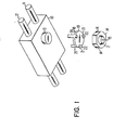
- the transducer carriage assembly includes a carriage body 10 shown journaled about a pair of precision guide rods 11 and 12 which are utilized for purposes of assembly and correspond to the rods or ways upon which the assembled carriage is mounted in the final drive structure for linear radial movement from one track location to another.
- Carriage body 10 also includes a downwardly depending mounting boss 13 to which the transducer, carried by a button 16, is attached.
- the transducer button is also shown in FIG. 3.
- the transducer pole pieces 15 are exposed at the surface 17 of the button 16.
- Flexible files normally include a tunnel erase wherein a pair of trailing erase gaps follow the data write gap to erase the fringe fields at each transverse side of the data track.
- the octagonal edge 14 is aligned with the leading end of the pole pieces 15 and octagonal edge 14' is aligned with the trailing ends of the pole pieces.
- the pole piece gaps occur transversely to the pole pieces 15 with the read/write gap occurring in the single element leading portion and the erase gaps respectively in the dual element trailing portion, with such gaps located near the crest of the convex surface 17.
- the adapter 18 includes a disk shaped central portion 19 from which extend three upper legs 20 (of which two are visible) and three lower legs 21 which present surfaces 22 that abut the upper surface of the transducer button 16 in the assembled condition.
- the adapter legs 20 radially confine the adapter with respect to the boss 13 when axially assembled thereabout.
- the penetration of the button 16 is the position along the axis 25.
- Yaw or azimuth is rotation of the button 16 (and thereby the transducer) about the axis 25.
- Roll is pivoting of the button 16 about an axis perpendicular to the axis 25 and substantially parallel to the major surfaces of the pole pieces 15.
- Pitch is pivotal movement of the button 16 about an axis perpendicular to the axis 25 and the major surfaces of the pole pieces 15.
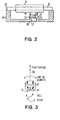
- FIG. 2 shows the carriage 10, button 16 and adapter 18 positioned in a fixture 26.
- the rods 11 and 12 rest on the fixture surface 24.
- Button 16 is supported and confined within an octagonal opening formed in the lower wall of fixture 26.
- the dimensional relationship between fixture surface 24 which engages rods 11 and 12 and the octagonal opening surface 28 against which button surface 27 rests, determines the penetration of button 16 and the positioning of the button respective to carriage body 10 with regard to pitch and roll.
- the adapter 18 With the adapter 18 positioned as illustrated in FIG. 2, the adapter is adhesively bonded to the mounting boss 13 preferably through the application of an adhesive to which a catalyst/curing agent is applied causing the adhesive to cure in a few seconds.
- the rotational position of the button 16 could be fixed using the proper disposition of the octagonal configuration in the fixture recess. This would permit bonding of the transducer button upper surface 23 to the lower leg surfaces 22 of adapter 18. This would complete the mechanical assembly of transducer button and supporting carriage while correcting the yaw or azimuth relationship of the transducer with respect to the carriage assembly.
Landscapes
- Supporting Of Heads In Record-Carrier Devices (AREA)
Applications Claiming Priority (2)
| Application Number | Priority Date | Filing Date | Title |
|---|---|---|---|
| US334112 | 1981-12-24 | ||
| US06/334,112 US4475281A (en) | 1981-12-24 | 1981-12-24 | Transducer head positioning adapter for fixed head flexible disk drives |
Publications (3)
| Publication Number | Publication Date |
|---|---|
| EP0082959A2 true EP0082959A2 (de) | 1983-07-06 |
| EP0082959A3 EP0082959A3 (en) | 1983-10-26 |
| EP0082959B1 EP0082959B1 (de) | 1986-02-19 |
Family
ID=23305625
Family Applications (1)
| Application Number | Title | Priority Date | Filing Date |
|---|---|---|---|
| EP82110827A Expired EP0082959B1 (de) | 1981-12-24 | 1982-11-23 | Verfahren zur Montage einer Wandlerkopfeinheit für Festkopf-Folienspeicherlaufwerke unter Verwendung eines Kopf-Positionierungsadapters |
Country Status (4)
| Country | Link |
|---|---|
| US (1) | US4475281A (de) |
| EP (1) | EP0082959B1 (de) |
| JP (1) | JPS58111161A (de) |
| DE (1) | DE3269245D1 (de) |
Families Citing this family (3)
| Publication number | Priority date | Publication date | Assignee | Title |
|---|---|---|---|---|
| JPS627676U (de) * | 1985-06-26 | 1987-01-17 | ||
| US4875122A (en) * | 1988-03-14 | 1989-10-17 | Eastman Kodak Company | Head transport assembly having simplified mutually independent positional adjustments |
| US6571454B1 (en) | 1999-07-23 | 2003-06-03 | Michael D. Haney | Drive test fixture |
Family Cites Families (3)
| Publication number | Priority date | Publication date | Assignee | Title |
|---|---|---|---|---|
| US2859084A (en) * | 1955-02-04 | 1958-11-04 | Monroe Calculating Machine | Mounting means for magnetic transducing heads |
| US3812579A (en) * | 1971-10-04 | 1974-05-28 | Metrolab Inc | Method of manufacturing magnetic drum memory apparatus |
| US4250530A (en) * | 1979-10-05 | 1981-02-10 | Yang Electromagnetic Systems Inc. | Fixed and movable supporting of dual magnetic heads |
-
1981
- 1981-12-24 US US06/334,112 patent/US4475281A/en not_active Expired - Fee Related
-
1982
- 1982-10-08 JP JP57176513A patent/JPS58111161A/ja active Granted
- 1982-11-23 EP EP82110827A patent/EP0082959B1/de not_active Expired
- 1982-11-23 DE DE8282110827T patent/DE3269245D1/de not_active Expired
Also Published As
| Publication number | Publication date |
|---|---|
| EP0082959A3 (en) | 1983-10-26 |
| JPH0219551B2 (de) | 1990-05-02 |
| DE3269245D1 (en) | 1986-03-27 |
| US4475281A (en) | 1984-10-09 |
| JPS58111161A (ja) | 1983-07-02 |
| EP0082959B1 (de) | 1986-02-19 |
Similar Documents
| Publication | Publication Date | Title |
|---|---|---|
| EP0918327B1 (de) | Plattenantrieb | |
| KR100248479B1 (ko) | 디스크 테이블 및 디스크 테이블의 제조방법 | |
| US4408238A (en) | Magnetic head arm assembly | |
| US7016155B2 (en) | Vibration-canceling mechanism and head gimbal assembly with the vibration-canceling mechanism | |
| US6771467B2 (en) | Vibration-canceling mechanism and head gimbal assembly with the vibration-canceling mechanism | |
| US6771466B2 (en) | Vibration-canceling mechanism and head gimbal assembly with the vibration-canceling mechanism | |
| US4992898A (en) | Magnetic head slider suspension assembly having inverted load rails | |
| US5608592A (en) | Head actuator | |
| EP0082959A2 (de) | Verfahren zur Montage einer Wandlerkopfeinheit für Festkopf-Folienspeicherlaufwerke unter Verwendung eines Kopf-Positionierungsadapters | |
| US4599666A (en) | Disk drive system apparatus band actuator | |
| US6963472B2 (en) | Flexural pivot for rotary disc drive actuator | |
| JPH11513836A (ja) | モールド成形されたアクチュエータの衝突停止装置 | |
| JPS62139133A (ja) | 光学系駆動装置 | |
| US4562501A (en) | Transducer support apparatus | |
| WO1996010820A1 (en) | Head-gimbal assembly with reduced static attitude bias | |
| US20040057160A1 (en) | Actuator assembly with out-of-plane voice coil | |
| JPH0516692Y2 (de) | ||
| JPS6258430A (ja) | 光学ヘツド装置 | |
| JP3462274B2 (ja) | 光ディスク装置 | |
| JPS60163291A (ja) | 磁気デイスク駆動装置 | |
| JPH05325460A (ja) | 磁気ヘッド | |
| KR970060135A (ko) | 광 디스크 기록 재생장치의 트레이장치 | |
| JPH0461677A (ja) | 光ディスク媒体 | |
| JPS62281114A (ja) | ジンバル型磁気ヘツドの製造方法 | |
| JPS61220137A (ja) | 光学ヘツド装置 |
Legal Events
| Date | Code | Title | Description |
|---|---|---|---|
| PUAI | Public reference made under article 153(3) epc to a published international application that has entered the european phase |
Free format text: ORIGINAL CODE: 0009012 |
|
| AK | Designated contracting states |
Designated state(s): DE FR GB |
|
| PUAL | Search report despatched |
Free format text: ORIGINAL CODE: 0009013 |
|
| AK | Designated contracting states |
Designated state(s): DE FR GB |
|
| 17P | Request for examination filed |
Effective date: 19831021 |
|
| GRAA | (expected) grant |
Free format text: ORIGINAL CODE: 0009210 |
|
| AK | Designated contracting states |
Designated state(s): DE FR GB |
|
| REF | Corresponds to: |
Ref document number: 3269245 Country of ref document: DE Date of ref document: 19860327 |
|
| ET | Fr: translation filed | ||
| PLBE | No opposition filed within time limit |
Free format text: ORIGINAL CODE: 0009261 |
|
| STAA | Information on the status of an ep patent application or granted ep patent |
Free format text: STATUS: NO OPPOSITION FILED WITHIN TIME LIMIT |
|
| 26N | No opposition filed | ||
| PGFP | Annual fee paid to national office [announced via postgrant information from national office to epo] |
Ref country code: GB Payment date: 19901012 Year of fee payment: 9 |
|
| PGFP | Annual fee paid to national office [announced via postgrant information from national office to epo] |
Ref country code: FR Payment date: 19901020 Year of fee payment: 9 |
|
| PGFP | Annual fee paid to national office [announced via postgrant information from national office to epo] |
Ref country code: DE Payment date: 19901124 Year of fee payment: 9 |
|
| PG25 | Lapsed in a contracting state [announced via postgrant information from national office to epo] |
Ref country code: GB Effective date: 19911123 |
|
| GBPC | Gb: european patent ceased through non-payment of renewal fee | ||
| PG25 | Lapsed in a contracting state [announced via postgrant information from national office to epo] |
Ref country code: FR Effective date: 19920731 |
|
| PG25 | Lapsed in a contracting state [announced via postgrant information from national office to epo] |
Ref country code: DE Effective date: 19920801 |
|
| REG | Reference to a national code |
Ref country code: FR Ref legal event code: ST |