EP0081751B1 - Rotierendes Detektorsystem mit Kühlmittelvorrat - Google Patents
Rotierendes Detektorsystem mit Kühlmittelvorrat Download PDFInfo
- Publication number
- EP0081751B1 EP0081751B1 EP82111131A EP82111131A EP0081751B1 EP 0081751 B1 EP0081751 B1 EP 0081751B1 EP 82111131 A EP82111131 A EP 82111131A EP 82111131 A EP82111131 A EP 82111131A EP 0081751 B1 EP0081751 B1 EP 0081751B1
- Authority
- EP
- European Patent Office
- Prior art keywords
- arrangement
- cooling
- detectors
- coolant
- detector system
- Prior art date
- Legal status (The legal status is an assumption and is not a legal conclusion. Google has not performed a legal analysis and makes no representation as to the accuracy of the status listed.)
- Expired
Links
- 238000001816 cooling Methods 0.000 claims description 34
- 239000002826 coolant Substances 0.000 claims description 21
- IJGRMHOSHXDMSA-UHFFFAOYSA-N Atomic nitrogen Chemical compound N#N IJGRMHOSHXDMSA-UHFFFAOYSA-N 0.000 claims description 10
- 239000007788 liquid Substances 0.000 claims description 8
- 229910052757 nitrogen Inorganic materials 0.000 claims description 5
- 229910052782 aluminium Inorganic materials 0.000 claims description 3
- 229910052732 germanium Inorganic materials 0.000 claims description 3
- GNPVGFCGXDBREM-UHFFFAOYSA-N germanium atom Chemical compound [Ge] GNPVGFCGXDBREM-UHFFFAOYSA-N 0.000 claims description 3
- 238000010521 absorption reaction Methods 0.000 claims description 2
- 238000000034 method Methods 0.000 claims description 2
- 239000004411 aluminium Substances 0.000 claims 1
- 239000004065 semiconductor Substances 0.000 claims 1
- 229910001220 stainless steel Inorganic materials 0.000 description 4
- 239000010935 stainless steel Substances 0.000 description 4
- RYGMFSIKBFXOCR-UHFFFAOYSA-N Copper Chemical compound [Cu] RYGMFSIKBFXOCR-UHFFFAOYSA-N 0.000 description 2
- XAGFODPZIPBFFR-UHFFFAOYSA-N aluminium Chemical compound [Al] XAGFODPZIPBFFR-UHFFFAOYSA-N 0.000 description 2
- 238000002591 computed tomography Methods 0.000 description 2
- 239000004020 conductor Substances 0.000 description 2
- 229910052802 copper Inorganic materials 0.000 description 2
- 239000010949 copper Substances 0.000 description 2
- 230000001419 dependent effect Effects 0.000 description 2
- 230000001105 regulatory effect Effects 0.000 description 2
- 230000010512 thermal transition Effects 0.000 description 2
- 210000003484 anatomy Anatomy 0.000 description 1
- 239000002131 composite material Substances 0.000 description 1
- 230000000694 effects Effects 0.000 description 1
- 238000001704 evaporation Methods 0.000 description 1
- 230000008020 evaporation Effects 0.000 description 1
- 239000007789 gas Substances 0.000 description 1
- 238000003384 imaging method Methods 0.000 description 1
- 210000000056 organ Anatomy 0.000 description 1
- 230000005855 radiation Effects 0.000 description 1
- 238000009834 vaporization Methods 0.000 description 1
- 230000008016 vaporization Effects 0.000 description 1
- 230000004304 visual acuity Effects 0.000 description 1
- 210000002268 wool Anatomy 0.000 description 1
Images
Classifications
-
- A—HUMAN NECESSITIES
- A61—MEDICAL OR VETERINARY SCIENCE; HYGIENE
- A61B—DIAGNOSIS; SURGERY; IDENTIFICATION
- A61B6/00—Apparatus or devices for radiation diagnosis; Apparatus or devices for radiation diagnosis combined with radiation therapy equipment
- A61B6/02—Arrangements for diagnosis sequentially in different planes; Stereoscopic radiation diagnosis
- A61B6/03—Computed tomography [CT]
- A61B6/032—Transmission computed tomography [CT]
- A61B6/035—Mechanical aspects of CT
-
- A—HUMAN NECESSITIES
- A61—MEDICAL OR VETERINARY SCIENCE; HYGIENE
- A61B—DIAGNOSIS; SURGERY; IDENTIFICATION
- A61B6/00—Apparatus or devices for radiation diagnosis; Apparatus or devices for radiation diagnosis combined with radiation therapy equipment
- A61B6/44—Constructional features of apparatus for radiation diagnosis
- A61B6/4488—Means for cooling
-
- F—MECHANICAL ENGINEERING; LIGHTING; HEATING; WEAPONS; BLASTING
- F17—STORING OR DISTRIBUTING GASES OR LIQUIDS
- F17C—VESSELS FOR CONTAINING OR STORING COMPRESSED, LIQUEFIED OR SOLIDIFIED GASES; FIXED-CAPACITY GAS-HOLDERS; FILLING VESSELS WITH, OR DISCHARGING FROM VESSELS, COMPRESSED, LIQUEFIED, OR SOLIDIFIED GASES
- F17C3/00—Vessels not under pressure
- F17C3/02—Vessels not under pressure with provision for thermal insulation
- F17C3/08—Vessels not under pressure with provision for thermal insulation by vacuum spaces, e.g. Dewar flask
-
- G—PHYSICS
- G01—MEASURING; TESTING
- G01T—MEASUREMENT OF NUCLEAR OR X-RADIATION
- G01T1/00—Measuring X-radiation, gamma radiation, corpuscular radiation, or cosmic radiation
- G01T1/16—Measuring radiation intensity
- G01T1/24—Measuring radiation intensity with semiconductor detectors
- G01T1/244—Auxiliary details, e.g. casings, cooling, damping or insulation against damage by, e.g. heat, pressure or the like
Definitions
- the invention relates to an arrangement for producing a body-sectional image, the image elements of which are derived from the absorption of ionizing rays, which pass through the corresponding body element in the body-sectional plane in different directions, with a rotating detector system that contains detectors arranged next to one another in the plane of movement a cooling system is assigned.
- a rotating detector system that contains detectors arranged next to one another in the plane of movement a cooling system is assigned.
- imaging systems such as computer tomography with detectors have the primary task of displaying the patient's anatomy as true to life as possible.
- the spatial resolving power should be as high as possible, as should the contrast with which neighboring organs or vessels stand out from one another.
- the recording time must be short enough to eliminate the effects of movement.
- detector systems for use in X-ray computed tomography are known, in which cooled germanium detectors are used Use. These detectors are attached via a support arm to a rectangular cooling tube through which liquid nitrogen flows and which is located inside the evacuated detector housing.
- pivotable detector systems are known (DE-A 1 27 41 404), in which the detectors are each mounted in groups on a base made of copper, which forms part of the evacuated detector housing and makes thermal contact with the coolant of the cooling bath.
- the invention is based on the object of creating a rotating detector system with a coolant supply which does not require an automatic mass compensation mechanism adapted to the coolant consumption.
- the stated object is now achieved in an arrangement for producing a body sectional image of the type mentioned at the outset with the characterizing features of claim 1.
- This arrangement with the two storage containers is moved at high speed around the object to be examined, for example a patient.
- the detectors arranged side by side in a row on the cooling finger can preferably be pressed onto the cooling finger using insulating pieces and clamping clips. This gives a good thermal transition.
- the coolant for example liquid nitrogen
- the coolant is evenly removed from the two containers by the centrifugal force and an adjustable regulating and control pressure and, in the liquid state, reaches the inlet connection of the detector system which contains the cooling finger.
- the cooling finger is dimensioned so that the coolant can transfer its heat of vaporization to the detectors, i. that is, the coolant leaves the cooling finger through the outlet port in the gaseous state.
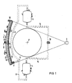
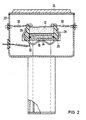
- FIG. 1 shows the entire arrangement and FIG. 2 shows a cross section of the detector system.
- a rotating detector system with 2, two coolant storage tanks with 4 and 5, the fulcrum of the system with P and the radiation source with 3, which supplies a fan-shaped beam with the aid of an aperture.
- the coolant reaches the inlet connection 8 of a cooling finger 10 via a cryogenic line 6.
- Detectors 12 are arranged next to one another on the cooling finger 10.
- the two coolant reservoirs 4 and 5 are connected to one another via a cryo line 14 and a pressure regulator 16.
- the cooling finger 10 is cryotechnically connected to the outer casing 22 on the inlet connection 8, an outlet connection 18 and on a support 20.
- a window 24 is provided, which can consist, for example, of a stainless steel / aluminum composite material.
- the coolant for example the liquid nitrogen
- the coolant reaches the cryogenic line 6 by the centrifugal force from the two storage containers 4 and 5 and is then pressed against the centrifugal force up to the center of the radius 11. From here, the coolant flows through the centrifugal force, which is dependent on the number of revolutions, to the inlet connection 8 of the cooling finger 10.
- the coolant is pumped through the cooling finger 10 with a force counter to the direction of rotation, which is indicated in the figure by an arrow D, and gives its own Evaporation heat.
- This force is made up of several individual forces, namely the centrifugal force dependent on the speed and radius, the pressure in the line, which is generated by the regulating and control pressure in the reservoir, and the pressure difference in the cooling finger, which depends on the distances between the Start and end of the cold finger from the pivot point P.
- the rotating detector system with coolant supply does not require an automatic mass balance adjustment adapted to the coolant consumption and that the cooling system can be designed for different operating times.
- the detectors 12 are pressed onto the cooling finger 10 by insulating pieces 26 and a clamping clip 28.
- Contact springs 30 are provided for the electrical contacting of the detectors 12.
- a film 32 is arranged between the detectors 12 and the cooling finger 10, which consists of a good heat-conducting and electrically conductive material and can be connected to an electrical connecting conductor, not shown in the figure, and can be led out of the outer jacket 22 with a vacuum-tight bushing.
- the cooling finger 10 is a cuboid hollow cylinder, which is preferably filled inside with chips 34, which may consist of copper chips or stainless steel wool, for example. The chips 34 inside the cooling finger 10 improve the heat exchange between the coolant and the detectors 12.
- This arrangement is surrounded by an outer jacket 22 in a vacuum-tight manner, which preferably consists of stainless steel and can be provided with a stainless steel / aluminum window 24.
- This design provides a good thermal transition between the detectors 12 and the cooling finger 10.
Landscapes
- Health & Medical Sciences (AREA)
- Engineering & Computer Science (AREA)
- Life Sciences & Earth Sciences (AREA)
- Physics & Mathematics (AREA)
- Medical Informatics (AREA)
- High Energy & Nuclear Physics (AREA)
- Molecular Biology (AREA)
- Biomedical Technology (AREA)
- General Health & Medical Sciences (AREA)
- Veterinary Medicine (AREA)
- Nuclear Medicine, Radiotherapy & Molecular Imaging (AREA)
- Optics & Photonics (AREA)
- Pathology (AREA)
- Radiology & Medical Imaging (AREA)
- Public Health (AREA)
- Heart & Thoracic Surgery (AREA)
- Surgery (AREA)
- Animal Behavior & Ethology (AREA)
- Biophysics (AREA)
- General Physics & Mathematics (AREA)
- Spectroscopy & Molecular Physics (AREA)
- Thermal Sciences (AREA)
- Mechanical Engineering (AREA)
- General Engineering & Computer Science (AREA)
- Pulmonology (AREA)
- Theoretical Computer Science (AREA)
- Measurement Of Radiation (AREA)
- Radiation Pyrometers (AREA)
- Apparatus For Radiation Diagnosis (AREA)
Applications Claiming Priority (2)
| Application Number | Priority Date | Filing Date | Title |
|---|---|---|---|
| DE3149705 | 1981-12-15 | ||
| DE19813149705 DE3149705A1 (de) | 1981-12-15 | 1981-12-15 | "rotierendes detektorsystem mit kuehlmittelvorrat" |
Publications (2)
| Publication Number | Publication Date |
|---|---|
| EP0081751A1 EP0081751A1 (de) | 1983-06-22 |
| EP0081751B1 true EP0081751B1 (de) | 1987-03-25 |
Family
ID=6148811
Family Applications (1)
| Application Number | Title | Priority Date | Filing Date |
|---|---|---|---|
| EP82111131A Expired EP0081751B1 (de) | 1981-12-15 | 1982-12-02 | Rotierendes Detektorsystem mit Kühlmittelvorrat |
Country Status (4)
| Country | Link |
|---|---|
| US (1) | US4456826A (enExample) |
| EP (1) | EP0081751B1 (enExample) |
| JP (1) | JPS58109034A (enExample) |
| DE (1) | DE3149705A1 (enExample) |
Families Citing this family (14)
| Publication number | Priority date | Publication date | Assignee | Title |
|---|---|---|---|---|
| EP0109206A3 (en) * | 1982-11-15 | 1985-08-21 | Picker International, Inc. | Computed tomography detection method and apparatus |
| US4709559A (en) * | 1985-08-01 | 1987-12-01 | Siemens Aktiengesellschaft | Cooling system for relatively movable components |
| JPS62180286A (ja) * | 1986-02-04 | 1987-08-07 | Japan Atom Energy Res Inst | ガス冷却型半導体放射線検出器 |
| JP2526870B2 (ja) * | 1986-08-19 | 1996-08-21 | 株式会社島津製作所 | 放射線像撮像装置 |
| DE8707038U1 (de) * | 1987-05-15 | 1988-09-15 | Siemens AG, 1000 Berlin und 8000 München | Computertomograph |
| DE3737159A1 (de) * | 1987-11-02 | 1989-05-11 | Steffel Gmbh Spezialmaschbau | Vorrichtung zur allseitigen roentgenpruefung eines drehbar abgestuetzten kraftfahrzeugreifens waehrend einer reifenumdrehung |
| US4969167A (en) * | 1988-11-25 | 1990-11-06 | Picker International, Inc. | CT scanner cooling duct |
| US5444752A (en) * | 1994-02-03 | 1995-08-22 | Analogic Corporation | Tomography detector temperature equalization |
| IL116717A (en) | 1996-01-09 | 1999-12-22 | Elop Electrooptics Ind Ltd | Optical tracing system |
| DE10058818A1 (de) * | 2000-11-27 | 2002-06-06 | Philips Corp Intellectual Pty | Röntgendetektor mit integrierter Kühlung |
| CN1283211C (zh) * | 2001-06-07 | 2006-11-08 | 株式会社日立医药 | X射线诊断设备 |
| JP4365762B2 (ja) * | 2004-09-30 | 2009-11-18 | 株式会社日立製作所 | 核医学診断装置および核医学診断装置の冷却方法 |
| US20090257548A1 (en) * | 2008-04-14 | 2009-10-15 | Ashutosh Joshi | Computed tomography system |
| DE102017208955A1 (de) * | 2017-05-29 | 2018-11-29 | Siemens Healthcare Gmbh | Detektorvorrichtung aufweisend einen Kühlluftpfad zum Kühlen eines Röntgendetektors |
Family Cites Families (2)
| Publication number | Priority date | Publication date | Assignee | Title |
|---|---|---|---|---|
| DE1931581A1 (de) * | 1969-06-21 | 1970-12-23 | Philips Nv | Kryostatdetektor |
| DE2741404A1 (de) * | 1977-09-14 | 1979-03-22 | Siemens Ag | Anordnung zum herstellen eines koerperschnittbildes |
-
1981
- 1981-12-15 DE DE19813149705 patent/DE3149705A1/de active Granted
-
1982
- 1982-09-30 US US06/429,868 patent/US4456826A/en not_active Expired - Fee Related
- 1982-12-02 EP EP82111131A patent/EP0081751B1/de not_active Expired
- 1982-12-14 JP JP57220023A patent/JPS58109034A/ja active Pending
Also Published As
| Publication number | Publication date |
|---|---|
| DE3149705C2 (enExample) | 1989-02-16 |
| EP0081751A1 (de) | 1983-06-22 |
| DE3149705A1 (de) | 1983-07-21 |
| US4456826A (en) | 1984-06-26 |
| JPS58109034A (ja) | 1983-06-29 |
Similar Documents
| Publication | Publication Date | Title |
|---|---|---|
| EP0081751B1 (de) | Rotierendes Detektorsystem mit Kühlmittelvorrat | |
| DE69226477T2 (de) | Magnet mit offenem Zutritt zur Bilderzeugung mittels magnetischer Resonanz | |
| DE102004061869B4 (de) | Einrichtung der Supraleitungstechnik und Magnetresonanzgerät | |
| DE69838866T2 (de) | Verbesserungen in oder mit Bezug auf Kryostatsystemen | |
| DE2423301C2 (de) | Vorrichtung zur erschütterungsfreien Übertragung von Kälte | |
| DE69932106T2 (de) | System zur Kühlung eines supraleitenden Läufers | |
| DE1938035C3 (de) | Kältepumpe | |
| DE69929402T2 (de) | Thermisch leitfähige Dichtung für einen supraleitenden Magneten ohne Verdampfungsverluste | |
| EP0361137A1 (de) | Magnetometer-Einrichtung mit einem Dewar-Gefäss zur Messung schwacher Magnetfelder | |
| DE19548273A1 (de) | NMR-Meßeinrichtung mit Pulsrohrkühler | |
| WO2003098645A1 (de) | Einrichtung der supraleitungstechnik mit einem supraleitenden magneten und einer kälteeinheit | |
| DE69430088T2 (de) | Röntgenstrahlen-Beugungsgerät mit Kühlmittel-Verbindung zur Röntgenröhre | |
| EP0398156B1 (de) | Verfahren und Vorrichtung zum Vorkühlen des Heliumtanks eines Kryostaten | |
| DE1751051B2 (de) | Kryostat mit einer vakuumkammer | |
| EP0225964A1 (de) | Vorrichtung zum Kühlen von Komponenten einer Röntgenanlage | |
| DE2906060C2 (de) | Kryostat | |
| DE3639760C2 (enExample) | ||
| DE3408138A1 (de) | Kryogenische magnetsysteme | |
| DE3750626T2 (de) | Modularer photonendetektor-cryostat, zusammenbau und system. | |
| DE8423909U1 (de) | Eulerwiege fuer tieftemperatur-diffraktometrie | |
| DE1439146B2 (de) | Vorrichtung zur Kühlung von Halbleiterelementen | |
| DE2856128C3 (de) | Kühlmittelanschlußkopf für eine elektrische Maschine, die einen um eine Achse drehbar gelagerten Läufer mit einer von einem Kühlmittel tiefzukühlenden, supraleitenden Wicklung enthält | |
| DE3435229A1 (de) | Kryostat fuer den betrieb einer (pfeil hoch)3(pfeil hoch)he-(pfeil hoch)4(pfeil hoch)he-mischeinheit | |
| DE1501319B2 (de) | Kryostat mit einem tiefsiedenden fluessigen kuehlmittel insbesondere zur kuehlung von supraleitungsspulen | |
| DE202025000367U1 (de) | Zentrier- und Justage-Einheit für einen Kryostat zur mechanischen Entkopplung und thermischen Zentrierung massiv schwerer Ge-Detektoren innerhalb eines Kryostaten-Systems |
Legal Events
| Date | Code | Title | Description |
|---|---|---|---|
| PUAI | Public reference made under article 153(3) epc to a published international application that has entered the european phase |
Free format text: ORIGINAL CODE: 0009012 |
|
| AK | Designated contracting states |
Designated state(s): FR NL |
|
| 17P | Request for examination filed |
Effective date: 19830727 |
|
| GRAA | (expected) grant |
Free format text: ORIGINAL CODE: 0009210 |
|
| AK | Designated contracting states |
Kind code of ref document: B1 Designated state(s): FR NL |
|
| PG25 | Lapsed in a contracting state [announced via postgrant information from national office to epo] |
Ref country code: NL Effective date: 19870325 |
|
| ET | Fr: translation filed | ||
| NLV1 | Nl: lapsed or annulled due to failure to fulfill the requirements of art. 29p and 29m of the patents act | ||
| PLBE | No opposition filed within time limit |
Free format text: ORIGINAL CODE: 0009261 |
|
| STAA | Information on the status of an ep patent application or granted ep patent |
Free format text: STATUS: NO OPPOSITION FILED WITHIN TIME LIMIT |
|
| 26N | No opposition filed | ||
| PGFP | Annual fee paid to national office [announced via postgrant information from national office to epo] |
Ref country code: FR Payment date: 19891221 Year of fee payment: 8 |
|
| PG25 | Lapsed in a contracting state [announced via postgrant information from national office to epo] |
Ref country code: FR Effective date: 19910830 |
|
| REG | Reference to a national code |
Ref country code: FR Ref legal event code: ST |