EP0081447B1 - Maschinen zur Entnahme von Futterblocks aus einem Silo - Google Patents
Maschinen zur Entnahme von Futterblocks aus einem Silo Download PDFInfo
- Publication number
- EP0081447B1 EP0081447B1 EP19820440042 EP82440042A EP0081447B1 EP 0081447 B1 EP0081447 B1 EP 0081447B1 EP 19820440042 EP19820440042 EP 19820440042 EP 82440042 A EP82440042 A EP 82440042A EP 0081447 B1 EP0081447 B1 EP 0081447B1
- Authority
- EP
- European Patent Office
- Prior art keywords
- machine
- cutting device
- housing
- knives
- sliding connecting
- Prior art date
- Legal status (The legal status is an assumption and is not a legal conclusion. Google has not performed a legal analysis and makes no representation as to the accuracy of the status listed.)
- Expired
Links
Images


Classifications
-
- A—HUMAN NECESSITIES
- A01—AGRICULTURE; FORESTRY; ANIMAL HUSBANDRY; HUNTING; TRAPPING; FISHING
- A01F—PROCESSING OF HARVESTED PRODUCE; HAY OR STRAW PRESSES; DEVICES FOR STORING AGRICULTURAL OR HORTICULTURAL PRODUCE
- A01F25/00—Storing agricultural or horticultural produce; Hanging-up harvested fruit
- A01F25/16—Arrangements in forage silos
- A01F25/20—Unloading arrangements
- A01F25/2027—Unloading arrangements for trench silos
- A01F25/2036—Cutting or handling arrangements for silage blocks
Definitions
- the present invention relates to a machine for removing fodder blocks from a silo.
- This machine comprises in particular a chassis provided at its lower part with teeth extending in a substantially horizontal plane and, at a certain distance above these teeth, a support carrying a cutting device.
- This comprises at least one knife and is guided along a U-shaped trajectory for the cutting of fodder blocks.
- the object of the present invention is a machine for removing blocks of fodder from a silo, without the above-mentioned drawbacks of known machines.
- an important characteristic of the invention consists in that, in the normal position for silage removal, the cutting device is inclined so that its knife (s) form an angle with the vertical and are directed in the direction advancement of said device, the infinite part of the coucom being located in front of the upper part relative to this same direction of advance, when they are outside the silage.
- This inclination compensates for the deformation due to the resistance of the forage during cutting.
- the said knife or knives are practically vertical during cutting.
- Said angle of inclination is advantageously adjustable as a function of the nature of the product to be cut, preferably between 1 and 10 °.
- the cutting device is articulated with respect to its support by means of a substantially horizontal axis, clamping means being provided for immobilization in the chosen position.
- the cutting device is tiltable on either side of the vertical. Therefore, it is possible to cut blocks by advancing the knife (s) from left to right or vice versa. There is therefore no need to return the empty knives to the starting position.
- the cutting device comprises two knives, each of these being fixed to a slide guided in translation in a housing, using means arranged on either side of said cutters slides and places near the two ends of said housing. This arrangement considerably improves the guidance of the slides, which leads to a reduction in deviations due to deformations at the level of the slides.
- the knives of the cutting device are narrower at their lower part than at their upper part. Thanks to this characteristic, the friction of the forage on the flanks of the knives, in particular when cornering, is reduced. This reduction in friction significantly reduces the deformations of the knives and consequently the risks of deviation.
- the knives of the cutting device are thinner at their lower part than at their upper part. This facilitates penetration and progression in the forage. This feature therefore also reduces the risk of knife deflection.
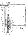
- the machine according to the invention comprises in particular a frame (1) forming a rigid frame.
- This chassis (1) has three coupling points for coupling to a tractor drive not shown. These coupling points consist of two lower pins (2) and an upper pin (3).
- Said chassis is also provided at its lower part with teeth (4) which extend in a substantially horizontal plane.
- a support arm (5) carrying at its outer end a cutting device (6).
- This essentially comprises two parallel knives (7 and 8) which extend downwards, substantially to the teeth (4) mentioned above. These two knives (7, 8) could also be replaced by a single knife.
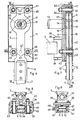
- said knives (7, 8) are driven in an alternating movement by means of a hydraulic motor (13) located on the rear side of the housing (11).
- the shaft (14) of this motor comprises two eccentric parts (15 and 16) each carrying a roller (17 and 18).
- Each roller (17 and 18) is engaged in a substantially horizontal orifice (19) provided on each of the slides (9 and 10).
- these rollers (17, 18) are rotated by means of the shaft (14) of the hydraulic motor (13), they cause a vertical displacement of the slides (9 and 10) and the knives (7 and 8) .
- These drive means are clearly shown in FIGS. 6 and 7.
- the support arm (5) of the cutting device (6) is screwed onto a handle (20) secured to a socket (21).
- this support arm (5) is articulated on a substantially vertical axis (22) of a crank (23).
- the latter is itself articulated on a plate (24) integral with the chassis (1), by means of a second articulation axis (25) eccentric relative to the first axis (22).
- this plate (24) comprises a sleeve (26) in which said hinge pin (25) is guided by means of tapered roller bearings not shown.
- Means are provided for driving the support arm (5) so that the cutting device (6) moves on a U-shaped trajectory (T), for cutting blocks of substantially rectangular shape.
- These means consist of a double-acting cylinder (27) arranged horizontally, which cylinder rotates the crank (23) around its articulation axis (25) via a chain (28) and a ring gear (29) integral with said crank (23) and, by two crowns (30 and 31) rotating the support arm (5) around its axis of articulation (22) with the crank (23).
- the crown (31) is integral with the support arm (5) and is concentric with its axis of articulation (22), while the other crown (30) is integral with the chassis (1) and is concentric with the axis d 'articulation (25) of the crank (23).
- the crown (31) integral with the support arm (5) is disposed inside the crown (30) and meshes therewith.
- the cutting device (6) is articulated on its support arm (5) by means of a substantially vertical axis (32). It is additionally connected to a rod (33) which is guided on a roller (34) situated substantially on the instantaneous center of rotation of said cutting device.
- This roller (34) is integral with an arm (35) connected to the upper part of the hinge pin (22) of the crank (23).
- the cutting device (6) in the normal position occupied by the machine for silage removal, the cutting device (6) is inclined so that the knives (7 and 8) form an angle (a) with the vertical (V ) and are directed in the direction of advance (A) of the device (6) when they are outside the silage.
- This inclination compensates for the deformation caused by the resistance of the forage during cutting. Indeed, as a result of this resistance, the knives (7, 8) are pushed towards the direction opposite to the direction of advance (A) and are thus brought back into a substantially vertical position during cutting.
- the lower part of the knives (7 and 8) is at the same level as their upper part during work. This prevents the lower parts from deviating towards the inside of the block to be cut in the corners of their trajectory (T).
- Said angle (a) formed by the knives (7, 8) with the vertical (V) is adjustable and is preferably between 1 and 10 °. We can thus choose their position according to the nature of the product to be desiled. Thus, when this product is dense and very packed, it is necessary to adopt a large angle (a) while in the opposite case it is necessary to reduce the value of this angle (a).
- the means for tilting the cutting head (6) consist of a plate (36), a substantially horizontal pivot (37) and tightening bolts (38). Said plate is arranged between the cutting device (6) and its support arm (5). It is fixed to said support arm by means of two lugs (39) connected to the hinge pin (32) around which the above-mentioned orientation of the cutting device (6) takes place.
- the pivot (37) is integral with the rear wall (40) of the housing (11) of the cutting device (6). It engages in a bore (41) provided in said plate (36). Finally, the tightening bolts (38) pass through the housing (11) and make it possible to immobilize the latter relative to the plate (36) in the chosen position. For this purpose, the holes of passage (42) of these bolts in the plate (36) are oblong.
- the pivot (37) is located near the bottom of the housing (11). In this way the upper part of the knives (7, 8) is slightly offset from the theoretical vertical position.
- a mark and graduations for adjusting the value of the angle (a).
- In the plate (36) is also provided an orifice (43) for the passage of the hydraulic motor (13).
- the cutting device (6) is advantageously tiltable on either side of the vertical (V). This characteristic makes it possible to cut blocks by advancing the knives (7, 8) from left to right or vice versa. There is therefore no need to return the cutting device (6) when empty to the same starting position for each cutting.
- the machine comprises means (44) for the automatic change of the inclination of the cutting device (6) with a view to cutting from the right to the left and vice versa.
- These means are in particular constituted by two latches (45 and 46) arranged on the rear wall (40) of the housing (11) and two stops (47) disposed on the chassis (1).
- it has on each side a tab (48) on which is fixed one of these stops (47) by means of bolts (49).
- the passage holes (50) of the latter in each tab (48) are oblong in order to be able to adjust the position of the stops (47).
- the cutting device (6) is articulated on a plate (36) by means of a pivot (37) which is nevertheless placed at the upper part of the housing (11).
- a shoulder screw (51) At the lower part of this housing is provided a shoulder screw (51) ensuring the guidance of the housing (11) relative to the plate (36).
- Each of said latches (45 and 46) is articulated on a substantially horizontal axis (52, 53).
- each has a tenon (54 and 55) intended to be housed in a notch (56 and 57) provided on the plate (36) for locking the cutting device (6) in one or the other. tilted positions.
- the knives (7, 8) form an angle (a) with the vertical (V) and are directed in the direction of travel (A).
- the knives (7, 8) are inclined on the other side relative to the vertical, which allows cutting in the direction of travel (B).
- the pins (54 and 55) are pushed into said notches (56 and 57) by means of a torsion spring (58) with double effect.
- This spring (58) is fixed to the rear wall (40) of the housing (11) by means of a screw (59).
- the latches (45 or 46) are actuated by the stops (47).
- each has a ramp (60) which comes into contact with the corresponding stop (47), when the cutting device (6) arrives towards the end of its trajectory (T).
- the stop exerts pressure on the corresponding latch (45 or 46) and makes it pivot around its articulation axis (52 or 53) so that its tenon (54 or 55) is released from the notch (56 or 57). (Position shown in dashed lines in Figure 5).
- the cutting device (6) thus unlocked pivots around the pivot (37) until it arrives in the position suitable for movement in the opposite direction, that is to say when the knives (7, 8) are on the other side with respect to the vertical (V) and again form an angle (a) with the latter.
- Said pivoting can be caused by the resistance of the fodder remaining to be cut or by the stop (47) against which the device (6) bears.
- said means (61) provide guidance in the direction perpendicular to the direction of advance (A or B) of the cutting device (6) so that there is play between the two slides (9 and 10) and between said slides (9 and 10) and the front (62) and rear (40) walls of the housing (11). This eliminates any risk of seizure due to possible deformations of the slides (9 and 10) in said direction perpendicular to the direction of advance (A or B).
- the guide means (61) of the slides (9 and 10) are constituted by rollers (63).
- rollers (63) For each slide (9 or 10) are provided four rollers (63) arranged on either side of said slide and near the ends of the housing (11). The distance between the upper rollers (63) and the lower rollers (63) is thus very large, which ensures better distribution of the loads and reduction of the operating clearance.
- rollers (63) are engaged in grooves (64) provided on the sides of the slides (9 and 10).
- rollers (63) are mounted on axes (65) guided both in the front wall (62) and the rear wall (40) of the housing (11). This provides very good stability when mounting the rollers (63).
- these axes (65) are also used for fixing the housing (11) on the plate (36) connected to the support arm (5).
- the two axes (65) located on the same side with respect to the slides (9 and 10) have a central part (66) which is eccentric with respect to its guided parts in the front and rear walls (62 and 40) of the housing (11) (see Figure 8).
- the corresponding rollers (63) are moved. This makes it possible to make up for any play in the guiding of the slides (9 and 10).
- the guide means (61) consist of needle plates (67) arranged on either side of the slides (9 and 10) near the ends of the housing (11). Each plate has two rows of needles practically forming a right angle between them.
- the slides (9 and 10) are guided by these plates (67) by means of their sides which are made in the form of a V for this purpose.
- These plates (67) also maintain a slight clearance both between the two slides (9 and 10) and between them and the front (62) and rear (40) walls of the housing (11).
- Said plates (67) are guided in rails (68) housed in the housing (11).
- the position of the rails (68) located on the same side with respect to the two slides (9 and 10) is adjustable by means of screws (69). This arrangement makes it possible to make up for any play between the slides (9 and 10) and the plates (67).
- the thickness (E) of the knives (7 and 8) is less important at their lower part than at their upper part (see FIG. 11). This also reduces the area subjected to the reaction of the forage. Thus said knives (7 and 8) penetrate and progress more easily in the silo, which reduces the deformations due to the resistance of the forage.
- the knives (7 and 8) have cutting teeth (70) on each of their threads. According to the invention, these teeth (70) are offset by the value of half a step (P) on one of the sides with respect to the other. Thanks to this offset, with respect to each notch between two teeth (70) is located a tooth (70) of the opposite flank (see FIG. 10). The section of each knife (7 or 8) is thus more constant, which makes it less deformable.
Landscapes
- Life Sciences & Earth Sciences (AREA)
- Environmental Sciences (AREA)
- Threshing Machine Elements (AREA)
Claims (25)
Applications Claiming Priority (2)
| Application Number | Priority Date | Filing Date | Title |
|---|---|---|---|
| FR8123061 | 1981-12-08 | ||
| FR8123061A FR2517509A1 (fr) | 1981-12-08 | 1981-12-08 | Perfectionnement aux machines pour le prelevement de blocs de fourrage dans un silo |
Publications (2)
| Publication Number | Publication Date |
|---|---|
| EP0081447A1 EP0081447A1 (de) | 1983-06-15 |
| EP0081447B1 true EP0081447B1 (de) | 1986-02-26 |
Family
ID=9264854
Family Applications (1)
| Application Number | Title | Priority Date | Filing Date |
|---|---|---|---|
| EP19820440042 Expired EP0081447B1 (de) | 1981-12-08 | 1982-12-03 | Maschinen zur Entnahme von Futterblocks aus einem Silo |
Country Status (3)
| Country | Link |
|---|---|
| EP (1) | EP0081447B1 (de) |
| DE (1) | DE3269510D1 (de) |
| FR (1) | FR2517509A1 (de) |
Cited By (1)
| Publication number | Priority date | Publication date | Assignee | Title |
|---|---|---|---|---|
| CN112219575A (zh) * | 2020-09-14 | 2021-01-15 | 安徽军松现代农业科技有限公司 | 一种农业生态用环保型秸秆处理回收设备及其使用方法 |
Families Citing this family (3)
| Publication number | Priority date | Publication date | Assignee | Title |
|---|---|---|---|---|
| FR2560490B1 (fr) * | 1984-03-02 | 1986-12-19 | Boton Freres | Tete de coupe a moyen de regulation du plan de coupe pour matiere ensilee |
| FR2610783B1 (fr) * | 1987-02-16 | 1990-04-20 | Kuhn Sa | Machine pour le prelevement de blocs de fourrage dans un silo |
| FR2610784B1 (fr) * | 1987-02-16 | 1990-04-13 | Kuhn Sa | Machine pour le prelevement de blocs de fourrage dans un silo |
Family Cites Families (3)
| Publication number | Priority date | Publication date | Assignee | Title |
|---|---|---|---|---|
| GB566252A (en) * | 1943-06-08 | 1944-12-20 | Reginald Charles Holden | Mechanically driven knife for cutting hay and for like purposes |
| DE2333052C3 (de) * | 1973-02-16 | 1979-03-29 | Hans Von Der 4533 Laggenbeck Heide | Vorrichtung zum Herausschneiden und Entnehmen von Blöcken aus einem Silofutterstock |
| US4277890A (en) * | 1978-03-30 | 1981-07-14 | Portnoff Lawrence A | Device for cutting multiple plies of material |
-
1981
- 1981-12-08 FR FR8123061A patent/FR2517509A1/fr active Granted
-
1982
- 1982-12-03 DE DE8282440042T patent/DE3269510D1/de not_active Expired
- 1982-12-03 EP EP19820440042 patent/EP0081447B1/de not_active Expired
Cited By (1)
| Publication number | Priority date | Publication date | Assignee | Title |
|---|---|---|---|---|
| CN112219575A (zh) * | 2020-09-14 | 2021-01-15 | 安徽军松现代农业科技有限公司 | 一种农业生态用环保型秸秆处理回收设备及其使用方法 |
Also Published As
| Publication number | Publication date |
|---|---|
| FR2517509B1 (de) | 1984-11-30 |
| FR2517509A1 (fr) | 1983-06-10 |
| DE3269510D1 (en) | 1986-04-03 |
| EP0081447A1 (de) | 1983-06-15 |
Similar Documents
| Publication | Publication Date | Title |
|---|---|---|
| EP1491122B1 (de) | Elektrisches Haushaltsgerät | |
| FR2771941A1 (fr) | Fixation de ski comportant deux elements de fixation deplacables sur une glissiere | |
| EP0081447B1 (de) | Maschinen zur Entnahme von Futterblocks aus einem Silo | |
| FR2823636A1 (fr) | Machine de fenaison, notamment une faucheuse avec un dispositif groupeur d'andains | |
| EP3345475B1 (de) | Mischbehälter mit seitenentladevorrichtung | |
| FR2852194A1 (fr) | Dispositif de securite pour un appareil d'elagage | |
| EP3054760B1 (de) | Heuerntemaschine mit verbesserter bodenanpassung | |
| FR2559995A1 (fr) | Dispositif de coupe et d'amenage pour une machine tractee ou bien attelee en trois points a un tracteur permettant de recolter du mais ou bien des plantes a tiges analogues | |
| FR2811195A1 (fr) | Dispositif de verrouillage d'un capot d'une machine de travail du sol | |
| FR2509570A1 (fr) | Dispositif destine a debiter des balles et des bottes de paille ou de fourrage | |
| EP0406140B1 (de) | Landmaschine mit teleskopischen Rotorträgern | |
| FR2558679A1 (fr) | Construction de rouleau pour une machine pour travailler le sol | |
| EP0071555B1 (de) | Maschine zur Entnahme von Futterballen aus einem Silo | |
| FR2596945A1 (fr) | Dispositif pour le prelevement d'une matiere compactee, et vehicule equipe dudit dispositif | |
| FR2625883A1 (fr) | Dispositif pour le reglage en inclinaison et/ou en hauteur d'un plan de travail ou de table d'un meuble | |
| FR3064879B1 (fr) | Systeme d'entrainement d'une machine agricole comportant une roue d'entrainement en contact avec le sol escamotable en position transport, et machine agricole avec un tel systeme d'entrainement | |
| EP0162795B1 (de) | Antrieb eines Silageblockschneiders | |
| FR2514229A1 (fr) | Machine pour le prelevement de blocs de fourrage dans un silo | |
| CA3074078A1 (fr) | Machine agricole et procede de pliage d'une machine agricole | |
| FR2749128A1 (fr) | Machine de recolte, en particulier moissonneuse-batteuse, comprenant un outil frontal compose d'au moins deux parties repliables | |
| FR2826233A1 (fr) | Machine de fenaison comportant un rotor muni d'outils de travail dont la distance par rapport au sol est reglable | |
| FR2559992A1 (fr) | Appareil de support de barre de coupe et dispositif a barre de coupe pour faucheuse rotative | |
| EP0733302A1 (de) | Heuwerbungsmaschine | |
| FR2696899A1 (fr) | Machine de fenaison pour l'andainage de fourrage. | |
| FR2769793A1 (fr) | Machine agricole de deroulage de balles rondes |
Legal Events
| Date | Code | Title | Description |
|---|---|---|---|
| PUAI | Public reference made under article 153(3) epc to a published international application that has entered the european phase |
Free format text: ORIGINAL CODE: 0009012 |
|
| AK | Designated contracting states |
Designated state(s): BE DE GB NL |
|
| 17P | Request for examination filed |
Effective date: 19831208 |
|
| GRAA | (expected) grant |
Free format text: ORIGINAL CODE: 0009210 |
|
| AK | Designated contracting states |
Designated state(s): BE DE GB NL |
|
| REF | Corresponds to: |
Ref document number: 3269510 Country of ref document: DE Date of ref document: 19860403 |
|
| PLBE | No opposition filed within time limit |
Free format text: ORIGINAL CODE: 0009261 |
|
| STAA | Information on the status of an ep patent application or granted ep patent |
Free format text: STATUS: NO OPPOSITION FILED WITHIN TIME LIMIT |
|
| 26N | No opposition filed | ||
| PGFP | Annual fee paid to national office [announced via postgrant information from national office to epo] |
Ref country code: GB Payment date: 19911126 Year of fee payment: 10 |
|
| PGFP | Annual fee paid to national office [announced via postgrant information from national office to epo] |
Ref country code: BE Payment date: 19911217 Year of fee payment: 10 |
|
| PG25 | Lapsed in a contracting state [announced via postgrant information from national office to epo] |
Ref country code: GB Effective date: 19921203 |
|
| PG25 | Lapsed in a contracting state [announced via postgrant information from national office to epo] |
Ref country code: BE Effective date: 19921231 |
|
| BERE | Be: lapsed |
Owner name: KUHN S.A. Effective date: 19921231 |
|
| GBPC | Gb: european patent ceased through non-payment of renewal fee |
Effective date: 19921203 |
|
| PGFP | Annual fee paid to national office [announced via postgrant information from national office to epo] |
Ref country code: DE Payment date: 19951229 Year of fee payment: 14 |
|
| PGFP | Annual fee paid to national office [announced via postgrant information from national office to epo] |
Ref country code: NL Payment date: 19951230 Year of fee payment: 14 |
|
| PG25 | Lapsed in a contracting state [announced via postgrant information from national office to epo] |
Ref country code: NL Effective date: 19970701 |
|
| NLV4 | Nl: lapsed or anulled due to non-payment of the annual fee |
Effective date: 19970701 |
|
| PG25 | Lapsed in a contracting state [announced via postgrant information from national office to epo] |
Ref country code: DE Effective date: 19970902 |