EP0081399B1 - Dispositif de commande de variation d'inclinaison des projecteurs de véhicules automobiles - Google Patents
Dispositif de commande de variation d'inclinaison des projecteurs de véhicules automobiles Download PDFInfo
- Publication number
- EP0081399B1 EP0081399B1 EP19820401992 EP82401992A EP0081399B1 EP 0081399 B1 EP0081399 B1 EP 0081399B1 EP 19820401992 EP19820401992 EP 19820401992 EP 82401992 A EP82401992 A EP 82401992A EP 0081399 B1 EP0081399 B1 EP 0081399B1
- Authority
- EP
- European Patent Office
- Prior art keywords
- lever
- arm
- hand
- web
- adjusting screws
- Prior art date
- Legal status (The legal status is an assumption and is not a legal conclusion. Google has not performed a legal analysis and makes no representation as to the accuracy of the status listed.)
- Expired
Links
- 238000007598 dipping method Methods 0.000 claims 1
- 230000008878 coupling Effects 0.000 description 2
- 238000010168 coupling process Methods 0.000 description 2
- 238000005859 coupling reaction Methods 0.000 description 2
- 230000001627 detrimental effect Effects 0.000 description 1
- 238000010586 diagram Methods 0.000 description 1
- 238000004519 manufacturing process Methods 0.000 description 1
Images

Classifications
-
- B—PERFORMING OPERATIONS; TRANSPORTING
- B60—VEHICLES IN GENERAL
- B60Q—ARRANGEMENT OF SIGNALLING OR LIGHTING DEVICES, THE MOUNTING OR SUPPORTING THEREOF OR CIRCUITS THEREFOR, FOR VEHICLES IN GENERAL
- B60Q1/00—Arrangement of optical signalling or lighting devices, the mounting or supporting thereof or circuits therefor
- B60Q1/02—Arrangement of optical signalling or lighting devices, the mounting or supporting thereof or circuits therefor the devices being primarily intended to illuminate the way ahead or to illuminate other areas of way or environments
- B60Q1/04—Arrangement of optical signalling or lighting devices, the mounting or supporting thereof or circuits therefor the devices being primarily intended to illuminate the way ahead or to illuminate other areas of way or environments the devices being headlights
- B60Q1/06—Arrangement of optical signalling or lighting devices, the mounting or supporting thereof or circuits therefor the devices being primarily intended to illuminate the way ahead or to illuminate other areas of way or environments the devices being headlights adjustable, e.g. remotely-controlled from inside vehicle
- B60Q1/068—Arrangement of optical signalling or lighting devices, the mounting or supporting thereof or circuits therefor the devices being primarily intended to illuminate the way ahead or to illuminate other areas of way or environments the devices being headlights adjustable, e.g. remotely-controlled from inside vehicle by mechanical means
- B60Q1/0683—Adjustable by rotation of a screw
-
- B—PERFORMING OPERATIONS; TRANSPORTING
- B60—VEHICLES IN GENERAL
- B60Q—ARRANGEMENT OF SIGNALLING OR LIGHTING DEVICES, THE MOUNTING OR SUPPORTING THEREOF OR CIRCUITS THEREFOR, FOR VEHICLES IN GENERAL
- B60Q2200/00—Special features or arrangements of vehicle headlamps
- B60Q2200/30—Special arrangements for adjusting headlamps, e.g. means for transmitting the movements for adjusting the lamps
- B60Q2200/36—Conjoint adjustments, i.e. a mechanical link allows conjoint adjustment of several units
Definitions
- Lever of a device for controlling the inclination of the inclination of motor vehicle headlamps in particular for the simultaneous control of the tilting of two independent headlamps arranged close to one another, such as a so-called "CODE” headlamp and a "ROAD" projector.
- control return lever is only authorized for simulated tilting of the projectors by acting on support stops integral with said projectors, moreover it does not include any flexibility capable of storing the initial adjustments. independent, manufacturing, assembly and adjustment tolerances, which can be detrimental for the proper functioning of a control device equipped with such a lever.
- the object of the present invention is to remedy these drawbacks and to this end relates to a lever of a device for controlling the inclination variation of the headlights of motor vehicles, in particular for the simultaneous control of the tilting of two independent headlights arranged close to the one on the other on a support fixed by adjusting screws which move in nuts, by means of said single control lever connected in a journalled fashion to the fixed support, characterized in that the lever comprises at least one control arm connected to the adjustment screw by a cardan device.
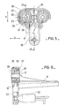
- the headlamps 1 and 2 respectively a headlamp for the "road” beam and the other for the "code” beam, are assembled independent and close to each other on the same support plate 4 by means of screws 7 which include ball joints 21 on which said projectors are snapped.
- a control lever (3) which acts simultaneously on the two projectors.
- control lever 3 comprises a stirrup 5 and a lifter 6 which connect the control arms 8 to the adjusting screws 7 by a gimbal device.
- control arm 8 is secured to the stirrup 5 and the adjustment screws 7 are held in nuts 17 secured to the lifter 6.
- the lifting beam 6 consists of a frame 16 which comprises on the one hand U-shaped ends open towards the outside in which the nuts 17 are held by vertical connections 18 and on the other hand in its central part, perpendicularly at the bases of U and between them, a cheek 20 connected to said bases by pins 19.
- connections 18 are of reduced section and preferably cylindrical so as to be able to deform elastically under the action of forces represented by the arrows A in FIG. 1.
- the stirrup 5 consists of a sole 9 which has on one of its sides the control arm 8, which is more particularly a manual control arm.
- the sole 9 On its upper face, the sole 9 has three parallel cheeks perpendicular to the axis of rotation of the hooks 10, the two ends of which 11 have a cradle 13 of the pins 19 of the lifter 6, and the third intermediate 12 of which is hollowed out in its central part and comprises at its free end an elastically deformable yoke 14.
- the cradles 13 are cylindrical holes split lengthwise into which the pins 19 snap into place.
- the elastically deformable yoke 14 consists of two half-rings 15 suspended face to face and spaced apart by a space at most equal to the thickness of the cheek 20 of the lifter 6.
- the bracket 5 may also include an arm 22 capable of receiving the end of a transducer 23 of a remote control.
- the lever 3 is then obtained simply by snap-fastening the pins 19 of the lifter 6 in the cradles 13 of the stirrup 5, the cheek 20 being interposed between the two half-rings 15 of the yoke 14.
- the coupling between the lifter and the stirrup is rigid so that any action of one of the arms 8 or 22 is reflected on the nuts 17 and consequently on the screws 7, but he is essential, also that the coupling includes a certain flexibility capable of absorbing various forces in particular during the mounting of the projectors 1 and 2 for the alignment of the axis of the screws 7 with the seat of their ball joint 21 integral with the projectors, these efforts are represented by the arrows A, B, and C in Figures 1 and 2.
- the screws 7 can also be inclined according to the arrows B by means of the pins 19 in their cradles 13.
- the elastically deformable yoke 14 then provides a reminder automatic lifting beam 6 so that it is automatically replaced in its correct orientation.
- the lever 24 is obtained in one piece from a sole 31 which includes, like that of the stirrup 5 of the embodiment precedence of the hooks 10, an arm 8 and may include an arm 22; the sole 31 supports a frame 25 which comprises on either side of an axis of symmetry a cylindrical ring 27 which with pins 26 and 28 plays the role of the gimbal which allows the various angular deflections of the nuts 17.
- Each nut 17 is concentrically connected to the corresponding ring 27 by the pins 28 arranged vertically, and each ring 27 is connected to the frame 25 by pins 26 arranged horizontally.
- the free spaces 29 and 30 are therefore interposed between the nut 17 the ring 27 and the frame 25 so that on the one hand the nut 17 can oscillate in the ring 27 thanks to the space 29, and that on the other hand the ring 27 can oscillate in the frame 25 thanks to the space 30.
- the frame 25 can be either in a closed assembly as shown in the left part of Figure 5, or open and therefore suspended, as shown in the right part of said Figure 5, by the central part of the frame made between the two rings 27.
Landscapes
- Engineering & Computer Science (AREA)
- Mechanical Engineering (AREA)
- Lighting Device Outwards From Vehicle And Optical Signal (AREA)
Applications Claiming Priority (2)
| Application Number | Priority Date | Filing Date | Title |
|---|---|---|---|
| FR8122127A FR2516877A1 (fr) | 1981-11-26 | 1981-11-26 | Levier d'un dispositif de commande de variation d'inclinaison des projecteurs de vehicules automobiles |
| FR8122127 | 1981-11-26 |
Publications (2)
| Publication Number | Publication Date |
|---|---|
| EP0081399A1 EP0081399A1 (fr) | 1983-06-15 |
| EP0081399B1 true EP0081399B1 (fr) | 1985-05-08 |
Family
ID=9264383
Family Applications (1)
| Application Number | Title | Priority Date | Filing Date |
|---|---|---|---|
| EP19820401992 Expired EP0081399B1 (fr) | 1981-11-26 | 1982-10-28 | Dispositif de commande de variation d'inclinaison des projecteurs de véhicules automobiles |
Country Status (4)
| Country | Link |
|---|---|
| EP (1) | EP0081399B1 (enExample) |
| DE (1) | DE3263690D1 (enExample) |
| ES (1) | ES517560A0 (enExample) |
| FR (1) | FR2516877A1 (enExample) |
Families Citing this family (6)
| Publication number | Priority date | Publication date | Assignee | Title |
|---|---|---|---|---|
| DE10238792A1 (de) * | 2002-08-23 | 2004-03-11 | Hella Kg Hueck & Co. | Scheinwerfer für Fahrzeuge |
| DE102004058269A1 (de) * | 2004-12-03 | 2006-07-20 | Hella Kgaa Hueck & Co. | Scheinwerfer für Fahrzeuge |
| US9120422B2 (en) * | 2012-06-29 | 2015-09-01 | Valeo North America, Inc. | Multiple headlamp adjuster linkage |
| FR3039798B1 (fr) * | 2015-08-06 | 2019-01-25 | Valeo Vision | Dispositif d'eclairage et/ou de signalisation d'un vehicule automobile comprenant au moins deux modules d'eclairage. |
| FR3052537B1 (fr) * | 2016-06-13 | 2020-06-19 | Valeo Iluminacion | Dispositif d'eclairage et/ou de signalisation de vehicule automobile avec correcteur d'orientation |
| WO2018041373A1 (en) * | 2016-09-05 | 2018-03-08 | HELLA GmbH & Co. KGaA | Headlamp with an improved light adjustment |
Family Cites Families (1)
| Publication number | Priority date | Publication date | Assignee | Title |
|---|---|---|---|---|
| FR2403237A1 (fr) * | 1977-09-15 | 1979-04-13 | Cibie Projecteurs | Correcteur d'orientation pour projecteurs de vehicules automobiles |
-
1981
- 1981-11-26 FR FR8122127A patent/FR2516877A1/fr active Granted
-
1982
- 1982-10-28 DE DE8282401992T patent/DE3263690D1/de not_active Expired
- 1982-10-28 EP EP19820401992 patent/EP0081399B1/fr not_active Expired
- 1982-11-22 ES ES517560A patent/ES517560A0/es active Granted
Also Published As
| Publication number | Publication date |
|---|---|
| EP0081399A1 (fr) | 1983-06-15 |
| ES8307617A1 (es) | 1983-08-16 |
| ES517560A0 (es) | 1983-08-16 |
| FR2516877A1 (fr) | 1983-05-27 |
| DE3263690D1 (en) | 1985-06-13 |
| FR2516877B1 (enExample) | 1984-01-27 |
Similar Documents
| Publication | Publication Date | Title |
|---|---|---|
| FR2618108A1 (fr) | Dispositif de fixation de feu avant sur un vehicule | |
| EP0081399B1 (fr) | Dispositif de commande de variation d'inclinaison des projecteurs de véhicules automobiles | |
| EP0580496A1 (fr) | Dispositif de réglage de l'orientation d'une partie mobile d'un projecteur de véhicule, et procédé de montage du dispositif | |
| FR2521083A1 (fr) | Retroviseur exterieur reglable par servo-moteurs pour vehicules automobiles | |
| EP0572313A1 (fr) | Dispositif de montage du genre rotule, notamment pour réflecteur de projecteur de véhicule automobile | |
| EP0016683B1 (fr) | Rétroviseur pour véhicule | |
| EP0416998B1 (fr) | Projecteur de véhicule automobile à moyens de réglage en site perfectionnés | |
| EP0494122B1 (fr) | Suspente articulée | |
| EP0444994B1 (fr) | Colonne de direction réglable | |
| EP0050999A1 (fr) | Colonne de direction réglable en hauteur | |
| EP1364600B1 (fr) | Système de réglage de fermeté pour rotule de sommier | |
| EP0096632B1 (fr) | Monture de siège pour véhicule automobile | |
| CA1093428A (fr) | Dispositif de manoeuvre par levier pour les commandes de climatisation d'un vehicule | |
| FR2559108A1 (fr) | Dispositif de reglage de l'orientation et de l'inclinaison d'un projecteur pour vehicules automobiles | |
| FR2871120A1 (fr) | Dispositif d'articulation a rotule d'un projecteur pour vehicules | |
| FR2554066A1 (fr) | Systeme de construction de retroviseurs de vehicules | |
| FR2599550A1 (fr) | Commutateur pour vehicules automobiles | |
| EP0028992B1 (fr) | Montage d'un élément à inclinaison réglable sur un support, notamment d'un dossier de siège sur un piètement, et siège pour enfant comportant application de ce montage | |
| FR2733189A3 (fr) | Dispositif de reglage pour un reflecteur d'un phare de vehicule automobile | |
| WO1984002313A1 (fr) | Systeme d'essuie-glace a culbuteur monte sur balai par un adaptateur | |
| WO2007033823A1 (fr) | Installation d'essuyage comportant un bras d'essuie-glace flexible et comportant des moyens pour faire varier la pression d'essuyage | |
| EP0756960B1 (fr) | Siège de véhicule automobile | |
| EP0565422B1 (fr) | Dispositif de montage d'une partie de projecteur de véhicule automobile | |
| FR2691114A1 (fr) | Dispositif de réglage par câbles, pour l'inclinaison de deux bourrelets latéraux d'un dossier de siège. | |
| FR2594392A1 (fr) | Retroviseur exterieur pour vehicule, comportant des moyens d'articulation simplifies |
Legal Events
| Date | Code | Title | Description |
|---|---|---|---|
| PUAI | Public reference made under article 153(3) epc to a published international application that has entered the european phase |
Free format text: ORIGINAL CODE: 0009012 |
|
| AK | Designated contracting states |
Designated state(s): DE GB IT |
|
| 17P | Request for examination filed |
Effective date: 19830701 |
|
| ITF | It: translation for a ep patent filed | ||
| GRAA | (expected) grant |
Free format text: ORIGINAL CODE: 0009210 |
|
| AK | Designated contracting states |
Designated state(s): DE GB IT |
|
| REF | Corresponds to: |
Ref document number: 3263690 Country of ref document: DE Date of ref document: 19850613 |
|
| PLBE | No opposition filed within time limit |
Free format text: ORIGINAL CODE: 0009261 |
|
| STAA | Information on the status of an ep patent application or granted ep patent |
Free format text: STATUS: NO OPPOSITION FILED WITHIN TIME LIMIT |
|
| 26N | No opposition filed | ||
| PG25 | Lapsed in a contracting state [announced via postgrant information from national office to epo] |
Ref country code: GB Effective date: 19881028 |
|
| PG25 | Lapsed in a contracting state [announced via postgrant information from national office to epo] |
Ref country code: DE Effective date: 19890701 |
|
| GBPC | Gb: european patent ceased through non-payment of renewal fee | ||
| IECL | Ie: translation for ep claims filed |