EP0081399B1 - Device for adjusting the inclination of headlamps for vehicles - Google Patents
Device for adjusting the inclination of headlamps for vehicles Download PDFInfo
- Publication number
- EP0081399B1 EP0081399B1 EP19820401992 EP82401992A EP0081399B1 EP 0081399 B1 EP0081399 B1 EP 0081399B1 EP 19820401992 EP19820401992 EP 19820401992 EP 82401992 A EP82401992 A EP 82401992A EP 0081399 B1 EP0081399 B1 EP 0081399B1
- Authority
- EP
- European Patent Office
- Prior art keywords
- lever
- arm
- hand
- web
- adjusting screws
- Prior art date
- Legal status (The legal status is an assumption and is not a legal conclusion. Google has not performed a legal analysis and makes no representation as to the accuracy of the status listed.)
- Expired
Links
Images

Classifications
-
- B—PERFORMING OPERATIONS; TRANSPORTING
- B60—VEHICLES IN GENERAL
- B60Q—ARRANGEMENT OF SIGNALLING OR LIGHTING DEVICES, THE MOUNTING OR SUPPORTING THEREOF OR CIRCUITS THEREFOR, FOR VEHICLES IN GENERAL
- B60Q1/00—Arrangement of optical signalling or lighting devices, the mounting or supporting thereof or circuits therefor
- B60Q1/02—Arrangement of optical signalling or lighting devices, the mounting or supporting thereof or circuits therefor the devices being primarily intended to illuminate the way ahead or to illuminate other areas of way or environments
- B60Q1/04—Arrangement of optical signalling or lighting devices, the mounting or supporting thereof or circuits therefor the devices being primarily intended to illuminate the way ahead or to illuminate other areas of way or environments the devices being headlights
- B60Q1/06—Arrangement of optical signalling or lighting devices, the mounting or supporting thereof or circuits therefor the devices being primarily intended to illuminate the way ahead or to illuminate other areas of way or environments the devices being headlights adjustable, e.g. remotely-controlled from inside vehicle
- B60Q1/068—Arrangement of optical signalling or lighting devices, the mounting or supporting thereof or circuits therefor the devices being primarily intended to illuminate the way ahead or to illuminate other areas of way or environments the devices being headlights adjustable, e.g. remotely-controlled from inside vehicle by mechanical means
- B60Q1/0683—Adjustable by rotation of a screw
-
- B—PERFORMING OPERATIONS; TRANSPORTING
- B60—VEHICLES IN GENERAL
- B60Q—ARRANGEMENT OF SIGNALLING OR LIGHTING DEVICES, THE MOUNTING OR SUPPORTING THEREOF OR CIRCUITS THEREFOR, FOR VEHICLES IN GENERAL
- B60Q2200/00—Special features or arrangements of vehicle headlamps
- B60Q2200/30—Special arrangements for adjusting headlamps, e.g. means for transmitting the movements for adjusting the lamps
- B60Q2200/36—Conjoint adjustments, i.e. a mechanical link allows conjoint adjustment of several units
Description
Levier d'un dispositif de commande de variation d'inclinaison des projecteurs de véhicules automobiles, notamment pour la commande simultanée du basculement de deux projecteurs indépendants disposés à proximité l'un de l'autre, tels qu'on projecteur dit »CODE« et un projecgteur dit »ROUTE«.Lever of a device for controlling the inclination of the inclination of motor vehicle headlamps, in particular for the simultaneous control of the tilting of two independent headlamps arranged close to one another, such as a so-called "CODE" headlamp and a "ROAD" projector.
Pour réaliser un tel basculement il est connu dans le brevet FR-A-2 233 822, d'utiliser un levier de renvoi commun en forme de fourche dont les extrémités des branches coopérent chacune avec l'un des projecteurs considérés.To achieve such a tilting, it is known in patent FR-A-2 233 822 to use a common return lever in the form of a fork, the ends of the branches of which each cooperate with one of the headlights considered.
Il peut être très avantageux de réaliser cette commande de basculement au niveau de certaines vis de réglage initial d'orientation dedits projecteurs, ceci afin de limiter le nombre de points de fixation et d'articulation par projecteur.It can be very advantageous to carry out this tilting command at the level of certain initial adjustment screws for orienting the headlights, in order to limit the number of fixing and articulation points per headlight.
Or dans le brevet mentionné ci-dessus le levier de renvoi de commande est seulement offecté au basculement simulatné des projecteurs en agissant sur des butées d'appui solidaires desdits projecteurs, de plus il ne comporte aucune souplesse susceptible d'emmagasiner les règla- ges initiaux indépendants, les tolérances de fabrication, d'assemblage et de réglage, ce qui peut êtrenéfaste pour le bon fonctionnement d'un dispositif de commande équipé d'un tel levier.However, in the patent mentioned above, the control return lever is only authorized for simulated tilting of the projectors by acting on support stops integral with said projectors, moreover it does not include any flexibility capable of storing the initial adjustments. independent, manufacturing, assembly and adjustment tolerances, which can be detrimental for the proper functioning of a control device equipped with such a lever.
La présente invention a pour but de remédier à ces inconvénients et concerne à cet effet un levier d'un dispositif de commande de variation d'inclinaison des projecteurs de véhicules automobiles, notamment pour la commande simultanée du basculement de deux projecteurs indépendants disposés proches l'un de l'autre sur un support fixé par des vis de réglage qui se déplacent dans des écrous, au moyen dudit levier de commande unique relié à tourillonnement au support fixé, caractérisé en ce que le levier comporte au moins un bras de commande relié aux vis de réglage par un dispositif à cardan.The object of the present invention is to remedy these drawbacks and to this end relates to a lever of a device for controlling the inclination variation of the headlights of motor vehicles, in particular for the simultaneous control of the tilting of two independent headlights arranged close to the one on the other on a support fixed by adjusting screws which move in nuts, by means of said single control lever connected in a journalled fashion to the fixed support, characterized in that the lever comprises at least one control arm connected to the adjustment screw by a cardan device.
La description qui va suivre en regard des schémas annexés fera mieux comprendre comment l'invention peut être réalisée.
- La figure 1 représente en vue de dessus un dispositif de commande de variation d'inclinaison de projecteurs équipé d'un levier conforme à l'invention.
- La figure 2 représente en vue frontale, suivant la flèche F de la figure 1, le levier de commande suivant un mode de réalisation.
- La figure 3 représente le levier de commande suivant la coupe 111 111 de la figure 2.
- La figure 4 représente le levier de commande suivant la coupe IV IV de la figure 2.
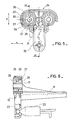
- La figure 5 représente une variante d'obtention d'un levier conforme à l'invention, dans laquelle la partie droite représente une réalisation possible, et la partie gauche une autre réalisation.
- La figure 6 représente un levier suivant la coupe VI VI de la figure 5.
- FIG. 1 shows a top view of a device for controlling the inclination of the headlights fitted with a lever according to the invention.
- Figure 2 shows in front view, along arrow F of Figure 1, the control lever according to one embodiment.
- FIG. 3 represents the control lever along the section 111 111 of FIG. 2.
- FIG. 4 represents the control lever according to section IV IV of FIG. 2.
- FIG. 5 represents a variant of obtaining a lever according to the invention, in which the right part represents a possible embodiment, and the left part another embodiment.
- FIG. 6 represents a lever according to section VI VI of FIG. 5.
Les projecteurs 1 et 2, respectivement un projecteur pour le faisceau »route« et l'autre pour le faisceau »code«, sont assemblés indépendants et à proximité l'un de l'autre sur une même platine support 4 au moyen de vis 7 qui comportent des rotules 21 sur lesquelles lesdits projecteurs sont encliquetés. Sur cette platine est articulé un levier de commande (3) qui agit simultanément sur les deux projecteurs.The
Conformément à l'invention et suivant un mode de réalisation le levier de commande 3, des figures 2 à 4 comporte un étrier 5 et un palonnier 6 qui relient les bras de commande 8 aux vis de réglage 7 par un dispositif à cardan.According to the invention and according to one embodiment the control lever 3, Figures 2 to 4 comprises a
Le bras de commande 8 est solidaire de l'étrier 5 et les vis de réglage 7 sont maintenues dans des écrous 17 solidaires du palonnier 6.The
Le palonnier 6 est constitué d'une armature 16 qui comporte d'une part des extrémités en forme de U ouverts vers l'extérieur dans lesquelles sont maintenus les écrous 17 par des liaisons verticales 18 et d'autre part en sa partie centrale, perpendiculairement aux bases de U et entre celles-ci, une joue 20 reliée aux dites bases par des tourillons 19.The
Les liaisons 18 sont de section réduite et de préférence cylindrique de façon à pouvoir se déformer élastiquement sous l'action de forces représentées par les flèches A sur la figure 1.The
L'étrier 5 est constitué d'une semelle 9 qui comporte sur un de ses côtés le bras de commande 8, qui est plus particulièrement un bras de commande manuel.The
Sous la face inférieure de la semelle 9 sont réalisés deux crochets 10 en forme d'anneaux cylindriques fendus aptes à encliqueter sur des tourillons solidaires de la platine support 4.Under the underside of the sole 9 are made two
Sur sa face supérieure la semelle 9 comporte trois joues parallèles perpendiculaires à l'axe de rotation des crochets 10, dont les deux extrêmes 11 comportentun berceau 13 des tourillons 19 du palonnier 6, et dont la troisième intermédiaire 12 est évidée en sa partie centrale et comporte à son extrémité libre une chape déformable élastiquement 14.On its upper face, the sole 9 has three parallel cheeks perpendicular to the axis of rotation of the
Les berceaux 13 sont des trous cylindiques fendus longidudinalement dans lesquelles s'encliquetent les tourillons 19.The
La chape déformable élastiquement 14 se compose de deux demianneaux 15 suspendus face à face et écartés d'un espace au plus égal à l'épaisseur de la joue 20 du palonnier 6.The elastically
Suivant une variante comme représentée à la figure 5 l'étrier 5 peut aussi comporter un bras 22 susceptible de recevoir l'extrémité d'un transducteur 23 d'une commande à distance.According to a variant as shown in Figure 5 the
L'obtention du levier 3 s'effectue alors simplement par l'encliquetage des tourillons 19 du palonnier 6 dans les berceaux 13 de l'étrier 5, la joue 20 étant intercallée entre les deux demianneaux 15 de la chape 14.The lever 3 is then obtained simply by snap-fastening the
Pour le bon fonctionnement d'un tel levier il est nécessaire que l'accouplement entre le palonnier et l'étrier soit rigide pour que toute action d'un des bras 8 ou 22 soit répercutée sur les écrous 17 et conséquemment sur les vis 7, mais il est indispensable, aussi que l'accouplement comporte une certaine souplesse susceptible d'absorber différents efforts notamment lors du montage des projecteurs 1 et 2 pour l'alignement de l'axe des vis 7 avec le siège de leur rotule 21 solidaire des projecteurs, ces efforts sont représentés par les flèches A, B, et C des figures 1 et 2.For the proper functioning of such a lever it is necessary that the coupling between the lifter and the stirrup is rigid so that any action of one of the
De part la présence des tourillons 18 les vis 7 peuvent légérement être orientées suivant les lèches A sans préjudice pour la liaison entre l'étrier 5 et le palonnier 6.Due to the presence of the
Les vis 7 peuvent aussi être inclinées suivant les flèches B grâce aux tourillons 19 dans leur berceaux 13.The
Il peut aussi apparaitre des efforts suivant les flèches C, les projecteurs n'étant pas assemblés simultanément, et dans ce cas l'étrier 5 et le palonnier 6 ne se trouvent pas dans un plan adéquat, la chape déformable élastiquement 14 assure alors un rappel automatique du palonnier 6 afin qu'il soit automatiquement replacé dans sa bonne orientation.It can also appear forces following the arrows C, the headlights not being assembled simultaneously, and in this case the
Suivant un autre mode de réalisation tel que représenté aux figures 5 et 6 le levier 24 est obtenu d'un seul tenant à partir d'une semelle 31 qui comporte comme celle de l'etrier 5 de la réalisation précédence des crochets 10, un bras 8 et peut comporter un bras 22; la semelle 31 supporte une armature 25 qui comporte de part et d'autre d'un axe de symétrie un anneau cylindrique 27 qui avec des tourillons 26 et 28 joue le rôle du cardan qui autorise les divers débattements angulaires des écrous 17. Chaque écrou 17 est relié concentriquement à l'anneau 27 correspondant par les tourillons 28 disposés verticalement, et chaque anneau 27 est relié à l'armature 25 par des tourillons 26 disposés horizontalement.According to another embodiment as shown in Figures 5 and 6 the
Les espaces libres 29 et 30 sont donc inter- callès entre l'écrou 17 l'anneau 27 et l'armature 25 afin que d'une part l'écrou 17 puisse osciller dans l'anneau 27 grâce à l'espace 29, et que d'autre part l'anneau 27 puisse osciller dans l'armature 25 grâce à l'espace 30. Ainsi lors de l'inclinaison d'une vis 7 suivant la flèche A l'écrou correspondant 17 oscille dans l'anneau 27 grâce aux tourillons 28 déformables élastiquement, l'anneau 27 étant immobilisé par les tourillons 26 dans l'armature 25, et lors de l'inclinaison d'une vis 7 suivant la flèche B, l'écrou 17 et l'anneau 27 sont concentriques et fixes l'un par rapport à l'autre, l'ensemble défini par l'écrou 17 et l'anneau 27 peut donc pivoter dans l'espace 30 autour de l'axe des tourillons déformables élastiquement 26.The
L'armature 25 peut se présenter soit suivant un ensemble fermé tel que représenté dans la partie gauche de la figure 5, soit ouvert et donc suspendu, tel que représenté dans la partie droite de ladite figure 5, par la partie centrale de l'armature réalisée entre les deux anneaux 27.The
Claims (7)
Applications Claiming Priority (2)
| Application Number | Priority Date | Filing Date | Title |
|---|---|---|---|
| FR8122127A FR2516877A1 (en) | 1981-11-26 | 1981-11-26 | LEVER OF A TILT VARIATION CONTROL DEVICE FOR MOTOR VEHICLE PROJECTORS |
| FR8122127 | 1981-11-26 |
Publications (2)
| Publication Number | Publication Date |
|---|---|
| EP0081399A1 EP0081399A1 (en) | 1983-06-15 |
| EP0081399B1 true EP0081399B1 (en) | 1985-05-08 |
Family
ID=9264383
Family Applications (1)
| Application Number | Title | Priority Date | Filing Date |
|---|---|---|---|
| EP19820401992 Expired EP0081399B1 (en) | 1981-11-26 | 1982-10-28 | Device for adjusting the inclination of headlamps for vehicles |
Country Status (4)
| Country | Link |
|---|---|
| EP (1) | EP0081399B1 (en) |
| DE (1) | DE3263690D1 (en) |
| ES (1) | ES8307617A1 (en) |
| FR (1) | FR2516877A1 (en) |
Families Citing this family (6)
| Publication number | Priority date | Publication date | Assignee | Title |
|---|---|---|---|---|
| DE10238792A1 (en) * | 2002-08-23 | 2004-03-11 | Hella Kg Hueck & Co. | Headlights for vehicles |
| DE102004058269A1 (en) * | 2004-12-03 | 2006-07-20 | Hella Kgaa Hueck & Co. | Headlights for vehicles |
| US9120422B2 (en) | 2012-06-29 | 2015-09-01 | Valeo North America, Inc. | Multiple headlamp adjuster linkage |
| FR3039798B1 (en) * | 2015-08-06 | 2019-01-25 | Valeo Vision | DEVICE FOR LIGHTING AND / OR SIGNALING A MOTOR VEHICLE COMPRISING AT LEAST TWO LIGHTING MODULES. |
| FR3052537B1 (en) * | 2016-06-13 | 2020-06-19 | Valeo Iluminacion | MOTOR VEHICLE LIGHTING AND / OR SIGNALING DEVICE WITH ORIENTATION CORRECTOR |
| WO2018041373A1 (en) * | 2016-09-05 | 2018-03-08 | HELLA GmbH & Co. KGaA | Headlamp with an improved light adjustment |
Family Cites Families (1)
| Publication number | Priority date | Publication date | Assignee | Title |
|---|---|---|---|---|
| FR2403237A1 (en) * | 1977-09-15 | 1979-04-13 | Cibie Projecteurs | ORIENTATION CORRECTOR FOR MOTOR VEHICLE HEADLIGHTS |
-
1981
- 1981-11-26 FR FR8122127A patent/FR2516877A1/en active Granted
-
1982
- 1982-10-28 DE DE8282401992T patent/DE3263690D1/en not_active Expired
- 1982-10-28 EP EP19820401992 patent/EP0081399B1/en not_active Expired
- 1982-11-22 ES ES517560A patent/ES8307617A1/en not_active Expired
Also Published As
| Publication number | Publication date |
|---|---|
| FR2516877B1 (en) | 1984-01-27 |
| FR2516877A1 (en) | 1983-05-27 |
| ES517560A0 (en) | 1983-08-16 |
| DE3263690D1 (en) | 1985-06-13 |
| ES8307617A1 (en) | 1983-08-16 |
| EP0081399A1 (en) | 1983-06-15 |
Similar Documents
| Publication | Publication Date | Title |
|---|---|---|
| FR2618108A1 (en) | DEVICE FOR FIXING A FRONT LIGHT ON A VEHICLE | |
| FR2671762A1 (en) | SUSPENSION SYSTEM WITH CROSS-BLADE SPRING. | |
| EP0122999B1 (en) | Joint rod for a seat with tilting back-rest, and adjustment device including such a rod | |
| EP0081399B1 (en) | Device for adjusting the inclination of headlamps for vehicles | |
| EP0572313A1 (en) | Ball fixation for the reflector of a vehicle headlamp | |
| EP0580496A1 (en) | Control device of the orientation of a movable part of a headlight and mounting thereof | |
| EP0016683B1 (en) | Vehicle rear-view mirrors | |
| EP0416998B1 (en) | Device for adjusting the inclination of the headlight of a vehicle | |
| FR2871120A1 (en) | Ball and socket joint device for headlight of motor vehicle e.g. car, has fastening body comprising retaining flanks to force ball and socket joint head in radial direction when head is stressed by extraction force | |
| EP1364600B1 (en) | Stiffness adjustment system for bed base ball joint | |
| EP0096632B1 (en) | Seat frame for an automotive vehicle | |
| EP0050999A1 (en) | Steering column adjustable in height | |
| EP0444994B1 (en) | Adjustable steering column | |
| WO2007033823A1 (en) | Wiping installation comprising a flexible windscreen drive arm and comprising means for varying the wiping pressure | |
| CA1093428A (en) | Lever for actuating air conditioning controls in vehicles | |
| FR2559108A1 (en) | Vehicle headlamp adjustment using single screw | |
| EP0317391A1 (en) | Device for maintaining in position approximately parallelepipedically shaped parts | |
| FR2625715A1 (en) | WIPER SYSTEM | |
| FR2733189A3 (en) | ADJUSTING DEVICE FOR A REFLECTOR OF A MOTOR VEHICLE HEADLIGHT | |
| EP0028992B1 (en) | Mounting of a member with adjustable inclination on a support, especially of a back-vest on a base, and child's seat making use of this mounting | |
| EP0269538A1 (en) | Draw-straighting arm and installation for straightening vehicle bodies or other deformed motor vehicle parts | |
| EP0694457B1 (en) | Wiping device having a deformable deflector mounted on a wiper which incorporates a flexible wiper blade | |
| EP0756960B1 (en) | Vehicle seat | |
| EP0307273B1 (en) | Vehicle rearview mirror support controlled by three cables | |
| WO1984002313A1 (en) | Windshield wiper system with rocker mounted on a blade by means of an adapter |
Legal Events
| Date | Code | Title | Description |
|---|---|---|---|
| PUAI | Public reference made under article 153(3) epc to a published international application that has entered the european phase |
Free format text: ORIGINAL CODE: 0009012 |
|
| AK | Designated contracting states |
Designated state(s): DE GB IT |
|
| 17P | Request for examination filed |
Effective date: 19830701 |
|
| ITF | It: translation for a ep patent filed |
Owner name: SOCIETA' ITALIANA BREVETTI S.P.A. |
|
| GRAA | (expected) grant |
Free format text: ORIGINAL CODE: 0009210 |
|
| AK | Designated contracting states |
Designated state(s): DE GB IT |
|
| REF | Corresponds to: |
Ref document number: 3263690 Country of ref document: DE Date of ref document: 19850613 |
|
| PLBE | No opposition filed within time limit |
Free format text: ORIGINAL CODE: 0009261 |
|
| STAA | Information on the status of an ep patent application or granted ep patent |
Free format text: STATUS: NO OPPOSITION FILED WITHIN TIME LIMIT |
|
| 26N | No opposition filed | ||
| PG25 | Lapsed in a contracting state [announced via postgrant information from national office to epo] |
Ref country code: GB Effective date: 19881028 |
|
| PG25 | Lapsed in a contracting state [announced via postgrant information from national office to epo] |
Ref country code: DE Effective date: 19890701 |
|
| GBPC | Gb: european patent ceased through non-payment of renewal fee | ||
| IECL | Ie: translation for ep claims filed |