EP0081032B1 - Vorrichtung zum Beschichten einer Bahn - Google Patents
Vorrichtung zum Beschichten einer Bahn Download PDFInfo
- Publication number
- EP0081032B1 EP0081032B1 EP82106894A EP82106894A EP0081032B1 EP 0081032 B1 EP0081032 B1 EP 0081032B1 EP 82106894 A EP82106894 A EP 82106894A EP 82106894 A EP82106894 A EP 82106894A EP 0081032 B1 EP0081032 B1 EP 0081032B1
- Authority
- EP
- European Patent Office
- Prior art keywords
- web
- coating
- pool
- liquid
- dam
- Prior art date
- Legal status (The legal status is an assumption and is not a legal conclusion. Google has not performed a legal analysis and makes no representation as to the accuracy of the status listed.)
- Expired
Links
Images


Classifications
-
- G—PHYSICS
- G03—PHOTOGRAPHY; CINEMATOGRAPHY; ANALOGOUS TECHNIQUES USING WAVES OTHER THAN OPTICAL WAVES; ELECTROGRAPHY; HOLOGRAPHY
- G03C—PHOTOSENSITIVE MATERIALS FOR PHOTOGRAPHIC PURPOSES; PHOTOGRAPHIC PROCESSES, e.g. CINE, X-RAY, COLOUR, STEREO-PHOTOGRAPHIC PROCESSES; AUXILIARY PROCESSES IN PHOTOGRAPHY
- G03C1/00—Photosensitive materials
- G03C1/74—Applying photosensitive compositions to the base; Drying processes therefor
-
- G—PHYSICS
- G03—PHOTOGRAPHY; CINEMATOGRAPHY; ANALOGOUS TECHNIQUES USING WAVES OTHER THAN OPTICAL WAVES; ELECTROGRAPHY; HOLOGRAPHY
- G03C—PHOTOSENSITIVE MATERIALS FOR PHOTOGRAPHIC PURPOSES; PHOTOGRAPHIC PROCESSES, e.g. CINE, X-RAY, COLOUR, STEREO-PHOTOGRAPHIC PROCESSES; AUXILIARY PROCESSES IN PHOTOGRAPHY
- G03C1/00—Photosensitive materials
- G03C1/74—Applying photosensitive compositions to the base; Drying processes therefor
- G03C2001/7444—Dip coating
Definitions
- This invention relates to coating apparatus in which a web of material passes through a coating station and surface of the web encounters a pool of coating liquid, the web thereafter leaving the coating station bearing a coating of the liquid on all but at least one side edge of the web surface, the apparatus comprising a wall member associated with the pool and acting as a dam to contain the pool adjacent the one side edge of the web, the dam being constructed and arranged to allow a greater width of the web to be coated as the liquid level in the pool rises, a rise in the liquid level thereby producing a coating on the web which moves towards the side edge of the web as the liquid level in the pool rises and replenishment means for replenishing coating liquid to the pool.
- US Patent 3081191 discloses an apparatus of the type indicated above for coating a wide, moving substrate or web with a non-Newtonian coating liquid by passing the web into contact with an elongated pool of such liquid, such that the part of the web being coated is itself one wall of the enclosure which forms the pool. In this manner, a portion of the liquid is carried away from the pool as a thin coating on the web. The pool thereby becomes deplenished. It is also important that margin control, i.e. control of the coating edge relative the adjacent web edge, be maintained.
- Margin control is usually achieved in the prior art by proportioning the coating station parts to achieve the desired results.
- Open loop methods involve merely supplying a constant flow to the pool, independent of the amount of liquid actually in the pool.
- Closed loop methods provide some means of sensing a parameter which is related in one way or another to the amount of liquid in the pool.
- An example of the latter is a replenishment pump whose pumping rate is a function of the speed to travel of the web.
- a more direct method uses a float-like device to measure the height of liquid within the pool.
- the present invention provides both closed loop margin control and closed loop liquid replenishment by the use of a single means.
- the present invention utilizes a direct sensing means, but does not require positioning a sensor at or in the coating liquid pool.
- the invention is characterised by sensing means associated with the web downstream of the coating station, the sensing means being responsive to the position of the edge of the coating relative to the side edge of the web, and being connected to control the replenishment means.
- a second similar wall member associated with the opposite end of the pool, second sensing means associated with the opposite side edge of said web, and means coordinating operation of the first and second sensing means to ensure that the sensing means whose coating edge is closer to its web edge is in control of the replenishment means.
- the present invention finds particular utility in the manufacture of flexible magnetic recording media.
- the web may comprise a wide webbiaxially oriented polyethylene terephthalate, acetates, polyolefins, or other conventional polymeric films which are in the range of 0.0381 mm (0.0015 inches) thick, and are from 609.6 mm (24 inches) to 1219.2 mm (48 inches) in width.
- the "magnetic ink" to be coated onto at least one side of such a substrate may vary widely in formulation. However, in all known instances, this ink is a non-Newtonian fluid, i.e. a fluid whose viscosity changes with rate of flow. Such fluids have also been described in thixotropic and pseudoplastic fluids.
- the volume of ink in the coating nip be relatively small, and that the ink be shielded from the effects of evaporation and contamination as much as is possible.
- the present invention accomplishes this result by a construction and arrangement which automatically provides a change in the width of the coating on the web, as a function of the height of coating liquid in the pool.
- the sensing of this width parameter can be used to control pool replenishment, and in addition, the resulting pool replenishment controls the coating width parameter.
- the present invention provides an elongated or linear pool, which for example is about 558.8 mm (22 inches) long when coating a 609.6 mm (24 inches) wide web.
- the two long sides or walls of the pool are made up of the coating head and the web being coated, respectively.
- the two ends of the pool are made up two small wedge-shaped walls or dams.
- these dams are constructed and arranged to allow the coating ink to leak out beyond the dam in a decreasing amount as the level of the ink in the dam decreases.
- Two sensors are located downstream of the coating head. The sensors are associated with the opposite side edges of the web, and the width of the narrowest of the uncoated side edges is used to control replenishment of ink to the pool.
- these dams are inclined or sloped so as to provide a longer pool as the height of the liquid in the pool increases.
- the liquid preferably does not leak out beyond the dam, towards the web edges.
- this third embodiment may also provide leakage which is avariable with liquid level, if desired.
- the present invention will be described in relation to a preferred embodiment of coating apparatus. However, the present invention finds utility in any coating apparatus in which a pool of coating liquid must be replenished.
- the preferred coating apparatus (Fig. 1) is similar to that disclosed in EP-003790, from which further details may be obtained.
- a travelling web 12 is engaged around a backup roller 14, which is mounted for rotation about an axis 15, and is driven at a circumferential speed equal to the linear speed at which the web 12 is moving.
- the roller 14 is, for example, 152.4 mm (6 inches) in diameter and 349.25 mm (13.75 inches) in axial length, a circular cylinder, 152.4 mm (6 inches) in diameter and 349.25 mm (13.75 inches) in axial length, and is made of highly polished metal.
- Guide rollers (not shown) direct the web 12 into contact with at least a substantial portion of the periphery of the backup roller 14.
- a stationary smoothing film 20 is positioned adjacent the web 12 around the periphery of backup roller 14.
- the film 20 extends over a substantial portion of the web 12 which is in contact with the backup roller 14, and extends beyond such contact.
- Pressure generating means in the form of a pliable membrane 22 carried on a metal mandrel 23 and secured to a support 24, urges the film 20 into contact with the web 12 with a predetermined static force which is a function of the internal pressure within the membrane 22.
- the membrane 22 is tubular in shape, approximately 38.1 mm (1.5 inches) in diameter, and somewhat longer than the film 20 is wide. The tubular axis of the membrane 22 extends parallel to the axis of the roller 14 for all positions of the membrane.
- Support 24 preferably allows for movement toward and away from backup roller 14 to vary the circumferential conformance length of membrane 22 to roller 14. For a fixed linear web speed, the greater the length of membrane conformance, the longer will be the coating zone, as measured in the direction of web travel, and the longer will be the residence time of the web in the coating zone.
- a conduit 26 communicates with the interior of the membrane 22 and also with pressure regulating means 28 to supply a fluid, preferably air, to the interior of membrane 22.
- a fluid preferably air
- a metering pump 50 provides coating liquid through an input conduit 34 to a manifold 35 feeding a reservoir or pool 37 (Fig. 2) of coating liquid at the confluence of the web 12 and film 20.
- the pump 50 normally operates to pump coating liquid at a nominal rate. This rate can be increased or decreased, both to maintain a desired level of liquid within the coating pool, and to control the width of the uncoated side margins of the web. If desired, the pump 50 could be operated in an on-off mode; however, modulation of the pumping rate about a nominal rate is preferred.
- the pool or reservoir 37 of coating liquid at the confluence of the film 20 and web 12 provides a readily controllable coating on web 12 with, in essence, force generated by membrane 22 controlling the thickness of the coating and the rate of resupply of the coating liquid controlling the width of the coating.
- the primary function of stationary smoothing film 20 is to provide an area of high shear force to the coating liquid. This in turn generates high hydrodynamic pressure, thus to spread and smooth the liquid coating material to a uniform thickness along the length of the web.
- a coated substrate is provided with liquid coating material evenly dispersed across the face of web 12 in a smooth and reproducable manner, and without a flow of surplus liqud coating material at the trailing end of smoothing film 20.
- the pool 37 is constrained at its opposite edges by wedge shaped walls 51 and 52 of plastics material.
- the front faces of these walls or dams approach, but do not touch, the moving web 12, whereas the rear faces of these walls engage the stationary smoothing film 20.
- the walls 51 and 52 supported from above, by attachment to the manifold 35, and are disposed closer together than the side edges 58 of the web 12.
- dams constituted in this embodiment by walls 51 and 52, can take a variety of forms within the scope of the present invention.
- the only requirement is that the width of the web 12 which is coated must increase as the quantity (i.e. height) of liquid in the pool 37 increases. This may be achieved in a number of ways.
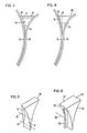
- a dam wall 53 (Fig. 3) has a front face 54 which is not concentric with the roller 14. As a result, a tapered gap 55 is formed between the front face 54 and the moving web 12. When the surface of the pool is at a low level 56 less coating liquid will leak out past the front face 54 than when the surface of the pool is at a high level 57.
- the gap 55 may be 1.27 mm (0.05 inches) wide at its widest, measured between front face 54 and web 12.
- the front face 54 of the dam wall 53 may be 12.7 mm (0.5 inches wide), measured in a direction parallel to the axis of roller 14, so that the length of the gap 55 remains constant throughout its height.
- a dam wall 60 has a front face 61 concentric with the roller 14, thereby to form with the moving web 12 a constant width gap 62 of, for example, 0.254 mm (0.01 inches).
- the front face 61 (Fig. 5) of dam wall 60 is a uniform 12.7 mm (0.5 inches) in length from the bottom up to a level 63. At this level, an inclined or bevelled plane 64 is formed, so that the length of the front face 61 diminishes above the level 63. Thus, the coating liquid experiences less resistance to leakage through gap 62 as the surface of liquid in the pool rises.
- the dam wall 60 in Fig. 5 replaces the dam wall 51 in Fig. 2, and a similar, but oppositely bevelled, dam wall replaces the dam wall 52.
- the plane 64 may be bevelled at less than 5° to the front face 61 of the dam wall 60. In practice it is desirable to control the pool surface to a level about the mid position of the plane 64, such as at level 65.
- the pump 50 (Fig. 1) can be controlled either to increase or decrease the pumping rate, as the level drops below or rises above the level 65, respectively.
- the gap between the front face of a dam wall and the moving web is never wide enough to allow unrestricted flow beyond the face, even when the pool is at its highest level, and for example the web is stationary.
- the rheology or surface tension of the liquid will prevent liquid from migrating completely across the front face before the liquid is carried away by the moving web.
- the liquid will flow toward the side edges of the web, and this effect is accelerated by operation of smoothing flap 20.
- Fig. 6 there may or may not be leakage past oppositely disposed dam walls.
- This embodiment operates to form a coating on the web whose width, is a function of the height of liquid in the coating pool, by providing a longer pool as the liquid height increases.
- Each dam wall 99 has side faces 100 and 101 which are vertical and a front face 102 which cooperates with the moving web 12.
- the dam wall 99 shown in Fig. 6 replaces the dam wall 51 in Fig. 2.
- the front face 102 has an inclined, or sloped, protruding wall 103 which establishes the operative length of the coating liquid pool, and is effective to expose a wider portion of web 12 to the coating liquid as the height of liquid within the pool increases.
- a similar dam wall with an oppositely inclined protruding wall replaces the dam wall 52 of Fig. 2.
- the width of the coating on a web can be controlled to ⁇ 6.35 mm (0.25 inches) about a nominal value, which nominal value is achieved when the surface of the liquid pool is at a level 104 about the mid position on the wall 103.
- the construction and arrangement of the front face of sloped wall 103 can include the liquid leakage arrangements of Figs. 3 or 4-5.
- the dam wall itself may have its side faces converge upwardly to achieve a similar leakage effect.
- the pump 50 (Fig. 1) is controlled to maintain the surface of the pool at a level such that a desired width of coating is achieved.
- the width of the coating on the web downstream of the coating station is sensed and used to control the pump 50.
- the web 12 (Fig. 7) has a coated area 70 whose side edges 71 and 72 are inboard of the side edges 73 and 74 of the web 12. Between the edges 71 and 73 and the edges 72 and 74, the web 12 is uncoated.
- Six aligned photocells 75, 76, 77, 78, 79 and 80 are spaced closely to web 12, but do not physically contact the same. These light responsive devices are sensitive to either light reflected off coating 70 and the uncoated portions of the web, or alternatively light transmitted through one but not the other. A light source (not shown) provides the reflected or transmitted light.
- Photocells 75 and 76 are disposed just inboard of the desired position of the edges 72 and 71, respectively, and are arranged to control pump 50.
- an OR circuit 81 is enabled and an "increase pumping rate" signal 82 is effective to increase the pumping rate of pump 50.
- the quantity of coating liquid within the pool 37 increases, the width of the coating increases and one or both of the coating edges begins to move towards the adjacent web edge 73 or 74.
- Photocells 77 and 78 are disposed just outboard of the desired position of the edges 72 and 71, respectively. As one or both of the coating edges reaches its adjacent photocell 77 or 78, the amount of light received by that photocell will decrease. This decrease in signal is inverted by a respective inverter 84 or 83. As a result, an OR circuit 85 is enabled and a "decrease pumping rate" signal 86 is effective to reduce the pumping rate of the pump 50.
- Photocells 79 and 80 are disposed immediately inboard of the edges 74 and 73, respectively, of the web 12.
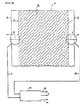
- FIG. 8 An alternative, more complex but more accurate, sensing and control arrangement is shown in Fig. 8.
- the photocells are replaced by two light sensitive viewing cameras 90 and 91 whose viewing reticles 92 and 93 provide fine-resolution signals 94 and 95 which define the uncoated widths between edges 71 and 73 and edges 72 and 74 of web 12.
- Signals 94 and 95 are connected as inputs to a programmable controller 96, this controller being programmed to provide signals 82, 86 and 88, as aforesaid.
- cameras 90 and 91 may be the Reticon LC 600 Line Scan Camera manufactued by E. G. & G. Company
- controller 96 may be the Reticon RS 8500 Camera Processor manufactured by E. G. & G. Company.
- Fig. 7 If it is desired to change the width to which a web is coated, in the Fig. 7 embodiment, this is achieved by moving pairs of photocells 76 and 78 and 75 and 77 transversely of the web 12, towards or away from each other. In the Fig. 8 embodiment, this is achieved by programming controller 96 to interrogate a different portion of viewing reticles 92 and 93. In both cases, the pumping rate of pump 50 will be changed, and the surface of the pool will be maintained at a different level, in order to satisfy the new closed loop control command that the web be coated to a width determined by the new positions of the photocells, or the new portion of the reticles which are being sensed. (Another form of coating apparatus to which this invention is applicable, is disclosed in US-A-3081191).
- the web may be coated up to its side edge on one side and spaced from the other side edge to leave only one uncoated strip.
Landscapes
- Chemical & Material Sciences (AREA)
- Engineering & Computer Science (AREA)
- Materials Engineering (AREA)
- Physics & Mathematics (AREA)
- General Physics & Mathematics (AREA)
- Coating Apparatus (AREA)
Claims (8)
Applications Claiming Priority (2)
| Application Number | Priority Date | Filing Date | Title |
|---|---|---|---|
| US325243 | 1981-11-27 | ||
| US06/325,243 US4357899A (en) | 1981-11-27 | 1981-11-27 | Coating apparatus |
Publications (2)
| Publication Number | Publication Date |
|---|---|
| EP0081032A1 EP0081032A1 (de) | 1983-06-15 |
| EP0081032B1 true EP0081032B1 (de) | 1985-10-02 |
Family
ID=23267042
Family Applications (1)
| Application Number | Title | Priority Date | Filing Date |
|---|---|---|---|
| EP82106894A Expired EP0081032B1 (de) | 1981-11-27 | 1982-07-30 | Vorrichtung zum Beschichten einer Bahn |
Country Status (4)
| Country | Link |
|---|---|
| US (1) | US4357899A (de) |
| EP (1) | EP0081032B1 (de) |
| JP (1) | JPS6033546B2 (de) |
| DE (1) | DE3266699D1 (de) |
Families Citing this family (7)
| Publication number | Priority date | Publication date | Assignee | Title |
|---|---|---|---|---|
| US4795510A (en) * | 1987-09-11 | 1989-01-03 | Kimberly-Clark Corporation | Process for applying reinforcing material to a diaper cover material |
| JPH07171467A (ja) * | 1991-09-02 | 1995-07-11 | Fuji Photo Film Co Ltd | 塗布方法及び装置 |
| EP0685761A1 (de) * | 1994-05-31 | 1995-12-06 | Eastman Kodak Company | Präzisionszentrierung eines mit einem photographischen lichtempfindlichen Material-beschichteten Bandes |
| US6891629B2 (en) * | 1999-06-30 | 2005-05-10 | Meadwestvaco Corporation | Method and apparatus for detecting a substrate feature |
| US6483587B1 (en) | 1999-06-30 | 2002-11-19 | John Charles Jackson | Gap/edge bead detection system |
| JP2012075980A (ja) * | 2010-09-30 | 2012-04-19 | Hirano Tecseed Co Ltd | 塗工装置 |
| US20260121014A1 (en) * | 2022-11-17 | 2026-04-30 | Zeon Corporation | Device for producing rolled grain layer and method of producing rolled grain layer using same |
Family Cites Families (5)
| Publication number | Priority date | Publication date | Assignee | Title |
|---|---|---|---|---|
| US3081191A (en) * | 1959-02-18 | 1963-03-12 | Mead Corp | Doctor blade |
| US3936549A (en) * | 1972-11-17 | 1976-02-03 | The Kohler Coating Machinery Corporation | Method and apparatus for applying a liquid coating to strip material |
| US4034707A (en) * | 1976-01-05 | 1977-07-12 | Rice Barton Corporation | Apparatus for coating webs |
| US4299186A (en) * | 1977-01-17 | 1981-11-10 | International Business Machines Corporation | Method and apparatus for applying a viscous fluid to a substrate |
| JPS54114546A (en) * | 1978-02-23 | 1979-09-06 | Ibm | Coating method and apparatus therefor |
-
1981
- 1981-11-27 US US06/325,243 patent/US4357899A/en not_active Expired - Fee Related
-
1982
- 1982-07-30 EP EP82106894A patent/EP0081032B1/de not_active Expired
- 1982-07-30 DE DE8282106894T patent/DE3266699D1/de not_active Expired
- 1982-09-20 JP JP57162417A patent/JPS6033546B2/ja not_active Expired
Also Published As
| Publication number | Publication date |
|---|---|
| JPS6033546B2 (ja) | 1985-08-03 |
| EP0081032A1 (de) | 1983-06-15 |
| DE3266699D1 (en) | 1985-11-07 |
| US4357899A (en) | 1982-11-09 |
| JPS5892481A (ja) | 1983-06-01 |
Similar Documents
| Publication | Publication Date | Title |
|---|---|---|
| US4442144A (en) | Method for forming a coating on a substrate | |
| US4327130A (en) | Method and apparatus for forming a coating on both sides of a substrate | |
| US5302206A (en) | Extrusion-type application device | |
| US6174372B1 (en) | Duplex type coating apparatus | |
| US5536313A (en) | Intermittent coating apparatus | |
| US4263870A (en) | Coating process | |
| JP3758098B2 (ja) | 塗布方法および塗布装置 | |
| JPH01194966A (ja) | 移動基体ヘコーティング物質を適用し且つ添加するための方法及び装置 | |
| US4357899A (en) | Coating apparatus | |
| US4121535A (en) | Hot melt pumping apparatus | |
| US4387124A (en) | Coating apparatus and method | |
| US5628827A (en) | Non-recirculating, die supplied doctored roll coater with solvent addition | |
| US6576296B1 (en) | Web coating method and apparatus for continuous coating over splices | |
| US3335026A (en) | Method for coating liquid compositions employing electrostatic field | |
| US5154951A (en) | Method and apparatus for use in bead coating a web with liquid composition | |
| SE465112B (sv) | Anordning foer kontinuerlig paafoering av en jaemn belaeggning paa en materialbana | |
| US4050410A (en) | Apparatus for the manufacture of a series of photoconductor webs | |
| US3573965A (en) | Multilayer coating method | |
| US4345543A (en) | Apparatus for forming a coating on a substrate | |
| US5683754A (en) | Process for forming coating on running film and apparatus therefor | |
| JPH03121480A (ja) | 液体現像装置 | |
| JP3544209B2 (ja) | ダイとドクターブレードと溶剤注入装置とを備えた非循環式ロールコータ | |
| EP0530751B1 (de) | Beschichtungsverfahren und Vorrichtung | |
| JPH08323961A (ja) | インキ等用粘度自動調整方法およびその装置 | |
| WO1992011572A1 (en) | Improvements in or relating to coating |
Legal Events
| Date | Code | Title | Description |
|---|---|---|---|
| PUAI | Public reference made under article 153(3) epc to a published international application that has entered the european phase |
Free format text: ORIGINAL CODE: 0009012 |
|
| AK | Designated contracting states |
Designated state(s): DE FR GB |
|
| 17P | Request for examination filed |
Effective date: 19830915 |
|
| GRAA | (expected) grant |
Free format text: ORIGINAL CODE: 0009210 |
|
| AK | Designated contracting states |
Designated state(s): DE FR GB |
|
| REF | Corresponds to: |
Ref document number: 3266699 Country of ref document: DE Date of ref document: 19851107 |
|
| ET | Fr: translation filed | ||
| PLBE | No opposition filed within time limit |
Free format text: ORIGINAL CODE: 0009261 |
|
| STAA | Information on the status of an ep patent application or granted ep patent |
Free format text: STATUS: NO OPPOSITION FILED WITHIN TIME LIMIT |
|
| 26N | No opposition filed | ||
| PGFP | Annual fee paid to national office [announced via postgrant information from national office to epo] |
Ref country code: GB Payment date: 19890630 Year of fee payment: 8 |
|
| PG25 | Lapsed in a contracting state [announced via postgrant information from national office to epo] |
Ref country code: FR Free format text: LAPSE BECAUSE OF NON-PAYMENT OF DUE FEES Effective date: 19900330 |
|
| PG25 | Lapsed in a contracting state [announced via postgrant information from national office to epo] |
Ref country code: DE Effective date: 19900403 |
|
| REG | Reference to a national code |
Ref country code: FR Ref legal event code: ST |
|
| PG25 | Lapsed in a contracting state [announced via postgrant information from national office to epo] |
Ref country code: GB Effective date: 19900730 |
|
| GBPC | Gb: european patent ceased through non-payment of renewal fee |