EP0080698A2 - Hochdruck-Injektionskopf für Kunststoffe - Google Patents
Hochdruck-Injektionskopf für Kunststoffe Download PDFInfo
- Publication number
- EP0080698A2 EP0080698A2 EP82110876A EP82110876A EP0080698A2 EP 0080698 A2 EP0080698 A2 EP 0080698A2 EP 82110876 A EP82110876 A EP 82110876A EP 82110876 A EP82110876 A EP 82110876A EP 0080698 A2 EP0080698 A2 EP 0080698A2
- Authority
- EP
- European Patent Office
- Prior art keywords
- mixing chamber
- high pressure
- pressure injection
- injection head
- cross
- Prior art date
- Legal status (The legal status is an assumption and is not a legal conclusion. Google has not performed a legal analysis and makes no representation as to the accuracy of the status listed.)
- Withdrawn
Links
- 238000002347 injection Methods 0.000 title claims abstract description 27
- 239000007924 injection Substances 0.000 title claims abstract description 27
- 239000000463 material Substances 0.000 title claims description 22
- 229920003023 plastic Polymers 0.000 title claims description 11
- 239000004033 plastic Substances 0.000 title claims description 11
- 238000004140 cleaning Methods 0.000 claims abstract description 21
- 238000004064 recycling Methods 0.000 description 6
- 238000013459 approach Methods 0.000 description 3
- 230000000694 effects Effects 0.000 description 2
- 239000000243 solution Substances 0.000 description 2
- 230000002411 adverse Effects 0.000 description 1
- 238000004891 communication Methods 0.000 description 1
- 238000010276 construction Methods 0.000 description 1
- 230000007423 decrease Effects 0.000 description 1
- 238000003754 machining Methods 0.000 description 1
- 238000012986 modification Methods 0.000 description 1
- 230000004048 modification Effects 0.000 description 1
- 238000011017 operating method Methods 0.000 description 1
- 238000012545 processing Methods 0.000 description 1
- 230000001737 promoting effect Effects 0.000 description 1
- 238000007493 shaping process Methods 0.000 description 1
Images
Classifications
-
- B—PERFORMING OPERATIONS; TRANSPORTING
- B29—WORKING OF PLASTICS; WORKING OF SUBSTANCES IN A PLASTIC STATE IN GENERAL
- B29B—PREPARATION OR PRETREATMENT OF THE MATERIAL TO BE SHAPED; MAKING GRANULES OR PREFORMS; RECOVERY OF PLASTICS OR OTHER CONSTITUENTS OF WASTE MATERIAL CONTAINING PLASTICS
- B29B7/00—Mixing; Kneading
- B29B7/74—Mixing; Kneading using other mixers or combinations of mixers, e.g. of dissimilar mixers ; Plant
- B29B7/76—Mixers with stream-impingement mixing head
- B29B7/7663—Mixers with stream-impingement mixing head the mixing head having an outlet tube with a reciprocating plunger, e.g. with the jets impinging in the tube
-
- B—PERFORMING OPERATIONS; TRANSPORTING
- B29—WORKING OF PLASTICS; WORKING OF SUBSTANCES IN A PLASTIC STATE IN GENERAL
- B29B—PREPARATION OR PRETREATMENT OF THE MATERIAL TO BE SHAPED; MAKING GRANULES OR PREFORMS; RECOVERY OF PLASTICS OR OTHER CONSTITUENTS OF WASTE MATERIAL CONTAINING PLASTICS
- B29B7/00—Mixing; Kneading
- B29B7/74—Mixing; Kneading using other mixers or combinations of mixers, e.g. of dissimilar mixers ; Plant
- B29B7/76—Mixers with stream-impingement mixing head
- B29B7/7631—Parts; Accessories
- B29B7/7636—Construction of the feed orifices, bores, ports
Definitions
- This invention relates to a high pressure injection head for plastics materials.
- high pressure injection heads include a mixing chamber wherein a self-cleaning piston can be caused to move, said piston performing the functions, both prior to and at the end of each injection steps, of shutting off the communication to the injectors and removing the material present in the mixing chamber.
- High pressure injection heads provide deflection of the flow of -material from the feed circuit to effect the so-called recycling step when no injection occurs in the mixing chamber, said recycling step taking place in accordance with two discrete operating procedures which may be defined as out-of-head recycle and in-head recycle.
- the heads with out-of-head recycle are arranged to deflect the oncoming flow of components prior to their introduction into the mixing chamber, by directing the plastics material component feed lines to a material recycle conduit.
- the heads with in-head recycle are instead provided with recycle channels which are arranged directly within the mixing chamber, and for example, directly in the self-cleaning piston which, according to the position occupied, can allow either the material injection step or recycle step.
- German Patent No. 2,815,460 teaches the use of a translatable piston inside the mixing chamber which incorporates the recycling conduits, within said piston there being arranged for sliding movement a circular cross-section self-cleaning piston.
- the recycling piston is given an oval cross-section purposely intended to prevent the piston from rotating about its own axis.
- the injectors are arranged in opposing relationship along the minor axis of the oval cross-section, but even with this expedient the mutual distance between the injectors is quite large owing to the presence of both the recycling piston and self-cleaning piston which still has a circular cross-section.
- the task of this invention is to. solve the foregoing problem by providing a high pressure injection head for plastic materials, whereby the mutual distance separating the injectors can be minimized, thus promoting a more intimate and uniform mixing of the reaction components without in any way jeopardizing the piston strength, and while affording an increased cross-sectional area of the mixing chamber to stop or at least minimize the turbulence generated through the material during the injection step and its outflow velocity into the mold.
- the self-cleaning piston is arranged to provide a thorough cleaning of the injector nozzles across the injection area of the injectors, without involving any special shaping of the injector shutter tips, as is instead carried out with approaches where the injector tip must be shaped to a cylindrical configuration combined with the self-cleaning piston having a circular cross-section with different diameters.
- a further object of this invention is to provide a high pressure injection head which brings about a substantially simplified construction with highly functional features.
- a high pressure injection head for plastics materials comprising a mixing chamber wherein a self-cleaning piston is arranged to be movable, characterized in that said mixing chamber has an elongate cross-sectional configuration with the injectors arranged in opposing relationship at locations of minimum mutual distance, inside said mixing chamber there being movable in sealed relationship said self-cleaning piston provided with a cross-sectional configuration matching said mixing chamber cross-sectional configuration.
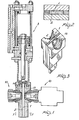
- the high pressure injection head of this invention comprises a mixing chamber 1, on the interior whereof a self-cleaning piston 2 is arranged to slide which is connected, for its axial travel movement in said mixing chamber 1, to a drive cylinder 3 which may be actuated directly by one of the reaction components.
- injectors are, in the exemplary embodiment shown, of the type for out-of-head recycle heads, that is therein the component introduced by the injector is delivered to the injector intake port located at an intake port 15 opened to the mixing chamber interior, or possibly diverted to the recycling conduits.
- the mixing chamber 1 has an elongate cross-sectional configuration with the injectors 10 arranged in opposing relationship at locations of minimum mutual distance, thereby the mixing of the components which are being introduced one against the other into the mixing chamber and hence into the mold is made more thorough and uniform.
- a preferred configuration for the mixing chamber is one with a rectangular cross-section and the injector nozzles positioned juxtaposed at a middle location along the major side, so as to minimize the mutual distance between the injector nozzles.
- the self-cleaning piston 2 which would also have a rectangular configuration, i.e. one matching the cross-section of the mixing chamber 1, during the downward stroke which follows the mixing and injection steps, scrapes the tips 14 of the injector shutters such as to remove any residual material therefrom.
- the above arrangement is particularly advantageous because the self-cleaning piston side facing the injectors can be made flat, thus making special or complex machining of the injector shutter tips, such as is required conventionally, quite unnecessary.
- the major side of the mixing chamber stands to the minor side thereof in a ratio ranging preferably from 3 to 5, said ratio being selected to suit the materials being handled and individual processing requirements.
- the advantage can be secured of having a large section mixing chamber, and hence the possibility of avoiding an undue increase of the material outflow velocity during the injection step, while keeping the distance between the injectors quite small.
- rectangular cross-section configuration has shown to be the most advantageous one, it would also be possible, in principle, to use other elongate shape configurations, such as an oval shape, a shape with plane-parallel faces joined together by circular portions, or any other shapes having a major dimension along a perpendicular direction to their minor dimension.
- the invention achieves its objects, and in particular, it should be pointed out that, as mentioned above, the high pressure injection head according to this invention affords the achievement of uniform and thorough mixing with the injectors located closer to one another, without involving constructional difficulties as concerns the self-cleaning piston.
- the materials used provided that they are compatible with the specific application, and the dimensions and contingent shapes may be any suitable ones to meet individual requirements.
Landscapes
- Engineering & Computer Science (AREA)
- Mechanical Engineering (AREA)
- Injection Moulding Of Plastics Or The Like (AREA)
- Processing And Handling Of Plastics And Other Materials For Molding In General (AREA)
Applications Claiming Priority (2)
| Application Number | Priority Date | Filing Date | Title |
|---|---|---|---|
| IT2537981 | 1981-12-01 | ||
| IT25379/81A IT1139885B (it) | 1981-12-01 | 1981-12-01 | Testa di iniezione ad alta pressione particolarmente per materie plastiche |
Publications (2)
| Publication Number | Publication Date |
|---|---|
| EP0080698A2 true EP0080698A2 (de) | 1983-06-08 |
| EP0080698A3 EP0080698A3 (de) | 1984-08-22 |
Family
ID=11216526
Family Applications (1)
| Application Number | Title | Priority Date | Filing Date |
|---|---|---|---|
| EP82110876A Withdrawn EP0080698A3 (de) | 1981-12-01 | 1982-11-24 | Hochdruck-Injektionskopf für Kunststoffe |
Country Status (2)
| Country | Link |
|---|---|
| EP (1) | EP0080698A3 (de) |
| IT (1) | IT1139885B (de) |
Cited By (6)
| Publication number | Priority date | Publication date | Assignee | Title |
|---|---|---|---|---|
| EP0164840A1 (de) * | 1984-04-13 | 1985-12-18 | Gusmer Corporation | Vorrichtung zur Abgabe eines Gemisches miteinander reaktionsfähiger Flüssigkeiten |
| EP0257221A3 (en) * | 1986-08-27 | 1988-12-07 | Klockner Ferromatik Desma Gmbh | Mixing head for making a chemically reactive mixture |
| WO2005097477A1 (en) * | 2004-04-05 | 2005-10-20 | Faculdade De Engenharia Da Universidade Do Porto | Production process of plastic parts by reaction injection moulding, and related head device |
| US7614780B2 (en) * | 2006-06-21 | 2009-11-10 | Afros S.P.A. | Method and apparatus with lobed nozzles, for mixing reactive chemical components |
| PT106166A (pt) * | 2012-02-20 | 2013-08-20 | Univ Do Porto | Câmara de mistura de jatos opostos para mistura de fluidos com diferentes débitos mássicos |
| EP3489001A1 (de) * | 2017-11-22 | 2019-05-29 | Afros S.P.A. | Vorrichtung zur fein- und gesteuerten einstellung eines spritzgiessverfahrens und zugehöriges industrieverfahren |
Family Cites Families (3)
| Publication number | Priority date | Publication date | Assignee | Title |
|---|---|---|---|---|
| BE779971R (fr) * | 1971-04-10 | 1972-06-16 | Krauss Maffei Ag | Appareil pour l'amorcage et la preparation d'un melange de deuxou de plusieurs constituants synthetiques dans la cavite de moulage d'un |
| GB1530339A (en) * | 1977-11-04 | 1978-10-25 | Viking Eng Co Ltd | Mixing head for foam plastics material |
| DE2815460C3 (de) * | 1978-04-10 | 1981-09-24 | Elastogran Maschinenbau GmbH, 2844 Lemförde | Mischvorrichtung für Mehrkomponentenkunststoffe, insbesondere Polyurethan |
-
1981
- 1981-12-01 IT IT25379/81A patent/IT1139885B/it active
-
1982
- 1982-11-24 EP EP82110876A patent/EP0080698A3/de not_active Withdrawn
Cited By (9)
| Publication number | Priority date | Publication date | Assignee | Title |
|---|---|---|---|---|
| EP0164840A1 (de) * | 1984-04-13 | 1985-12-18 | Gusmer Corporation | Vorrichtung zur Abgabe eines Gemisches miteinander reaktionsfähiger Flüssigkeiten |
| EP0257221A3 (en) * | 1986-08-27 | 1988-12-07 | Klockner Ferromatik Desma Gmbh | Mixing head for making a chemically reactive mixture |
| WO2005097477A1 (en) * | 2004-04-05 | 2005-10-20 | Faculdade De Engenharia Da Universidade Do Porto | Production process of plastic parts by reaction injection moulding, and related head device |
| US7708918B2 (en) | 2004-04-05 | 2010-05-04 | Faculdade De Engenharia Da Universidade Do Porto | Production process of plastic parts by reaction injection moulding, and related head device |
| US7614780B2 (en) * | 2006-06-21 | 2009-11-10 | Afros S.P.A. | Method and apparatus with lobed nozzles, for mixing reactive chemical components |
| PT106166A (pt) * | 2012-02-20 | 2013-08-20 | Univ Do Porto | Câmara de mistura de jatos opostos para mistura de fluidos com diferentes débitos mássicos |
| EP3489001A1 (de) * | 2017-11-22 | 2019-05-29 | Afros S.P.A. | Vorrichtung zur fein- und gesteuerten einstellung eines spritzgiessverfahrens und zugehöriges industrieverfahren |
| CN109986808A (zh) * | 2017-11-22 | 2019-07-09 | 艾弗若斯股份公司 | 精确和可控地调节注射成型工艺的装置和相关工业方法 |
| US11285680B2 (en) | 2017-11-22 | 2022-03-29 | Afros S.P.A. | Apparatus for fine and controlled adjustment of an injection molding process and related industrial process |
Also Published As
| Publication number | Publication date |
|---|---|
| EP0080698A3 (de) | 1984-08-22 |
| IT1139885B (it) | 1986-09-24 |
| IT8125379A0 (it) | 1981-12-01 |
Similar Documents
| Publication | Publication Date | Title |
|---|---|---|
| CA1209104A (en) | Plural component dispensing device | |
| CA2147458C (en) | Co-injection manifold for injection molding | |
| US4582224A (en) | Nozzle for mixing at least two flowable reaction components | |
| US4473531A (en) | Rim mixhead with high pressure recycle | |
| US4653997A (en) | Injection mold apparatus with gas ejection | |
| CA1331265C (en) | Injection die for injecting two components | |
| EP0405007B1 (de) | Spritzgiesssystem mit einer Buchse mit doppelter Zufuhr, montiert im Verteilerkanal | |
| EP0080698A2 (de) | Hochdruck-Injektionskopf für Kunststoffe | |
| HK1003136B (en) | Injection nozzle | |
| CA2255613A1 (en) | Process and apparatus for forming plastic articles | |
| HK1003136A1 (en) | Injection nozzle | |
| US4740089A (en) | Movable-chamber mixing head | |
| DE69122265T2 (de) | Signalgeber | |
| US4634825A (en) | Apparatus for scavenging the erosion zone of spark-erosive cutting plants | |
| US5063027A (en) | Apparatus for mixing at least two reactive plastic materials | |
| GB1441798A (en) | Nozzles for liquid plastics material | |
| US4884962A (en) | Multiple sprew bar stack mold | |
| US5795600A (en) | Melt ducting arrangement for injection molding nozzle | |
| CA2156784A1 (en) | Molding press apparatus | |
| US5295508A (en) | Mixing apparatus for processing liquid multi-component plastics, in particular polyurethane | |
| US4505592A (en) | Apparatus for producing a mixture from two or more plastic components | |
| CA1272869A (en) | Apparatus for the preparation of a reaction mixture from liquid components | |
| US5201580A (en) | Impingement mixing device | |
| US4876071A (en) | Mixing apparatus for synthetic resin with multiple resin components | |
| US4082251A (en) | Mixing head for a machine for producing multicomponent plastics |
Legal Events
| Date | Code | Title | Description |
|---|---|---|---|
| PUAI | Public reference made under article 153(3) epc to a published international application that has entered the european phase |
Free format text: ORIGINAL CODE: 0009012 |
|
| AK | Designated contracting states |
Designated state(s): AT DE FR GB SE |
|
| PUAL | Search report despatched |
Free format text: ORIGINAL CODE: 0009013 |
|
| AK | Designated contracting states |
Designated state(s): AT DE FR GB SE |
|
| STAA | Information on the status of an ep patent application or granted ep patent |
Free format text: STATUS: THE APPLICATION IS DEEMED TO BE WITHDRAWN |
|
| 18D | Application deemed to be withdrawn |
Effective date: 19850423 |
|
| RIN1 | Information on inventor provided before grant (corrected) |
Inventor name: RIVA, PAOLO Inventor name: MARIANI, VITTORIO |