EP0080698A2 - High pressure injection head for plastics materials - Google Patents
High pressure injection head for plastics materials Download PDFInfo
- Publication number
- EP0080698A2 EP0080698A2 EP82110876A EP82110876A EP0080698A2 EP 0080698 A2 EP0080698 A2 EP 0080698A2 EP 82110876 A EP82110876 A EP 82110876A EP 82110876 A EP82110876 A EP 82110876A EP 0080698 A2 EP0080698 A2 EP 0080698A2
- Authority
- EP
- European Patent Office
- Prior art keywords
- mixing chamber
- high pressure
- pressure injection
- injection head
- cross
- Prior art date
- Legal status (The legal status is an assumption and is not a legal conclusion. Google has not performed a legal analysis and makes no representation as to the accuracy of the status listed.)
- Withdrawn
Links
Images
Classifications
-
- B—PERFORMING OPERATIONS; TRANSPORTING
- B29—WORKING OF PLASTICS; WORKING OF SUBSTANCES IN A PLASTIC STATE IN GENERAL
- B29B—PREPARATION OR PRETREATMENT OF THE MATERIAL TO BE SHAPED; MAKING GRANULES OR PREFORMS; RECOVERY OF PLASTICS OR OTHER CONSTITUENTS OF WASTE MATERIAL CONTAINING PLASTICS
- B29B7/00—Mixing; Kneading
- B29B7/74—Mixing; Kneading using other mixers or combinations of mixers, e.g. of dissimilar mixers ; Plant
- B29B7/76—Mixers with stream-impingement mixing head
- B29B7/7663—Mixers with stream-impingement mixing head the mixing head having an outlet tube with a reciprocating plunger, e.g. with the jets impinging in the tube
-
- B—PERFORMING OPERATIONS; TRANSPORTING
- B29—WORKING OF PLASTICS; WORKING OF SUBSTANCES IN A PLASTIC STATE IN GENERAL
- B29B—PREPARATION OR PRETREATMENT OF THE MATERIAL TO BE SHAPED; MAKING GRANULES OR PREFORMS; RECOVERY OF PLASTICS OR OTHER CONSTITUENTS OF WASTE MATERIAL CONTAINING PLASTICS
- B29B7/00—Mixing; Kneading
- B29B7/74—Mixing; Kneading using other mixers or combinations of mixers, e.g. of dissimilar mixers ; Plant
- B29B7/76—Mixers with stream-impingement mixing head
- B29B7/7631—Parts; Accessories
- B29B7/7636—Construction of the feed orifices, bores, ports
Definitions
- This invention relates to a high pressure injection head for plastics materials.
- high pressure injection heads include a mixing chamber wherein a self-cleaning piston can be caused to move, said piston performing the functions, both prior to and at the end of each injection steps, of shutting off the communication to the injectors and removing the material present in the mixing chamber.
- High pressure injection heads provide deflection of the flow of -material from the feed circuit to effect the so-called recycling step when no injection occurs in the mixing chamber, said recycling step taking place in accordance with two discrete operating procedures which may be defined as out-of-head recycle and in-head recycle.
- the heads with out-of-head recycle are arranged to deflect the oncoming flow of components prior to their introduction into the mixing chamber, by directing the plastics material component feed lines to a material recycle conduit.
- the heads with in-head recycle are instead provided with recycle channels which are arranged directly within the mixing chamber, and for example, directly in the self-cleaning piston which, according to the position occupied, can allow either the material injection step or recycle step.
- German Patent No. 2,815,460 teaches the use of a translatable piston inside the mixing chamber which incorporates the recycling conduits, within said piston there being arranged for sliding movement a circular cross-section self-cleaning piston.
- the recycling piston is given an oval cross-section purposely intended to prevent the piston from rotating about its own axis.
- the injectors are arranged in opposing relationship along the minor axis of the oval cross-section, but even with this expedient the mutual distance between the injectors is quite large owing to the presence of both the recycling piston and self-cleaning piston which still has a circular cross-section.
- the task of this invention is to. solve the foregoing problem by providing a high pressure injection head for plastic materials, whereby the mutual distance separating the injectors can be minimized, thus promoting a more intimate and uniform mixing of the reaction components without in any way jeopardizing the piston strength, and while affording an increased cross-sectional area of the mixing chamber to stop or at least minimize the turbulence generated through the material during the injection step and its outflow velocity into the mold.
- the self-cleaning piston is arranged to provide a thorough cleaning of the injector nozzles across the injection area of the injectors, without involving any special shaping of the injector shutter tips, as is instead carried out with approaches where the injector tip must be shaped to a cylindrical configuration combined with the self-cleaning piston having a circular cross-section with different diameters.
- a further object of this invention is to provide a high pressure injection head which brings about a substantially simplified construction with highly functional features.
- a high pressure injection head for plastics materials comprising a mixing chamber wherein a self-cleaning piston is arranged to be movable, characterized in that said mixing chamber has an elongate cross-sectional configuration with the injectors arranged in opposing relationship at locations of minimum mutual distance, inside said mixing chamber there being movable in sealed relationship said self-cleaning piston provided with a cross-sectional configuration matching said mixing chamber cross-sectional configuration.
- the high pressure injection head of this invention comprises a mixing chamber 1, on the interior whereof a self-cleaning piston 2 is arranged to slide which is connected, for its axial travel movement in said mixing chamber 1, to a drive cylinder 3 which may be actuated directly by one of the reaction components.
- injectors are, in the exemplary embodiment shown, of the type for out-of-head recycle heads, that is therein the component introduced by the injector is delivered to the injector intake port located at an intake port 15 opened to the mixing chamber interior, or possibly diverted to the recycling conduits.
- the mixing chamber 1 has an elongate cross-sectional configuration with the injectors 10 arranged in opposing relationship at locations of minimum mutual distance, thereby the mixing of the components which are being introduced one against the other into the mixing chamber and hence into the mold is made more thorough and uniform.
- a preferred configuration for the mixing chamber is one with a rectangular cross-section and the injector nozzles positioned juxtaposed at a middle location along the major side, so as to minimize the mutual distance between the injector nozzles.
- the self-cleaning piston 2 which would also have a rectangular configuration, i.e. one matching the cross-section of the mixing chamber 1, during the downward stroke which follows the mixing and injection steps, scrapes the tips 14 of the injector shutters such as to remove any residual material therefrom.
- the above arrangement is particularly advantageous because the self-cleaning piston side facing the injectors can be made flat, thus making special or complex machining of the injector shutter tips, such as is required conventionally, quite unnecessary.
- the major side of the mixing chamber stands to the minor side thereof in a ratio ranging preferably from 3 to 5, said ratio being selected to suit the materials being handled and individual processing requirements.
- the advantage can be secured of having a large section mixing chamber, and hence the possibility of avoiding an undue increase of the material outflow velocity during the injection step, while keeping the distance between the injectors quite small.
- rectangular cross-section configuration has shown to be the most advantageous one, it would also be possible, in principle, to use other elongate shape configurations, such as an oval shape, a shape with plane-parallel faces joined together by circular portions, or any other shapes having a major dimension along a perpendicular direction to their minor dimension.
- the invention achieves its objects, and in particular, it should be pointed out that, as mentioned above, the high pressure injection head according to this invention affords the achievement of uniform and thorough mixing with the injectors located closer to one another, without involving constructional difficulties as concerns the self-cleaning piston.
- the materials used provided that they are compatible with the specific application, and the dimensions and contingent shapes may be any suitable ones to meet individual requirements.
Abstract
The high pressure injection head comprises an elongate configuration cross-section mixing chamber (1) wherein a self-cleaning piston (2), having a cross-sectional configuration matching that of the mixing chamber, can be moved in sealed relationship, the injectors (10) of the head being arranged in opposing relationship at flat areas of minimal mutual distance.
Description
- This invention relates to a high pressure injection head for plastics materials.
- As is known, high pressure injection heads include a mixing chamber wherein a self-cleaning piston can be caused to move, said piston performing the functions, both prior to and at the end of each injection steps, of shutting off the communication to the injectors and removing the material present in the mixing chamber.
- High pressure injection heads provide deflection of the flow of -material from the feed circuit to effect the so-called recycling step when no injection occurs in the mixing chamber, said recycling step taking place in accordance with two discrete operating procedures which may be defined as out-of-head recycle and in-head recycle.
- The heads with out-of-head recycle are arranged to deflect the oncoming flow of components prior to their introduction into the mixing chamber, by directing the plastics material component feed lines to a material recycle conduit.
- The heads with in-head recycle are instead provided with recycle channels which are arranged directly within the mixing chamber, and for example, directly in the self-cleaning piston which, according to the position occupied, can allow either the material injection step or recycle step.
- All of the above embodiments require that the injectors can be kept as close together as possible, such that as the mutual distance decreases during the injection step, an improved and more complete mixing can take place.
- However, this requirement meets opposition in the fact that it is not possible to reduce, beyond certain limits, the useful cross-section of the self-cleaning piston which slides inside the mixing chamber, because the piston would otherwise be rendered mechanically weak, while the reduced cross-section area, for the same flow rate, would result in an unacceptable increase of the plastic material flow velocity from the mixing chamber, with attendant increase in the material turbulence, which could produce flaws in the pieces being processed; furthermore, as the injection is carried out with an open mold, an excessively high velocity may result in material splashing, impact flaws, etc.
- Solutions adopted heretofore, which make use of a circular cross-section self-cleaning piston, provide, in order to allow the injectors to be kept relatively close together and attenuate the adverse effects of velocity, additional chambers located downstream of the mixing chamber proper, possibly having their axes set at an angle to the mixing chamber.
- Another approach, disclosed in German Patent No. 2,815,460, teaches the use of a translatable piston inside the mixing chamber which incorporates the recycling conduits, within said piston there being arranged for sliding movement a circular cross-section self-cleaning piston.
- With this approach, the recycling piston is given an oval cross-section purposely intended to prevent the piston from rotating about its own axis. In accordance with that embodiment, the injectors are arranged in opposing relationship along the minor axis of the oval cross-section, but even with this expedient the mutual distance between the injectors is quite large owing to the presence of both the recycling piston and self-cleaning piston which still has a circular cross-section.
- Accordingly the task of this invention is to. solve the foregoing problem by providing a high pressure injection head for plastic materials, whereby the mutual distance separating the injectors can be minimized, thus promoting a more intimate and uniform mixing of the reaction components without in any way jeopardizing the piston strength, and while affording an increased cross-sectional area of the mixing chamber to stop or at least minimize the turbulence generated through the material during the injection step and its outflow velocity into the mold.
- Within this task it is an object of the invention to provide an injection head,whereiti the self-cleaning piston is arranged to provide a thorough cleaning of the injector nozzles across the injection area of the injectors, without involving any special shaping of the injector shutter tips, as is instead carried out with approaches where the injector tip must be shaped to a cylindrical configuration combined with the self-cleaning piston having a circular cross-section with different diameters.
- A further object of this invention is to provide a high pressure injection head which brings about a substantially simplified construction with highly functional features.
- According to one aspect of the invention the above task and objects, as well as yet other objects, such as will be apparent hereinafter, are achieved by a high pressure injection head for plastics materials, comprising a mixing chamber wherein a self-cleaning piston is arranged to be movable, characterized in that said mixing chamber has an elongate cross-sectional configuration with the injectors arranged in opposing relationship at locations of minimum mutual distance, inside said mixing chamber there being movable in sealed relationship said self-cleaning piston provided with a cross-sectional configuration matching said mixing chamber cross-sectional configuration.
- Further features and advantages will be more apparent from the following description of a preferred, but not limitative, embodiment of a high pressure injection head for plasticsmaterials, as illustrated by way of example only in the accompanying drawing, where:
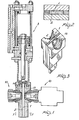
- Figure 1 is a sectional view of the high pressure injection head according to the invention;
- Figure 2 is a sectional view taken along the line II-II of Figure 1; and
- Figure 3 is a partly cut-away perspective view showing in detail the mixing chamber and self-cleaning piston.
- Making reference to the drawing figures, the high pressure injection head of this invention comprises a
mixing chamber 1, on the interior whereof a self-cleaning piston 2 is arranged to slide which is connected, for its axial travel movement in saidmixing chamber 1, to adrive cylinder 3 which may be actuated directly by one of the reaction components. - Provided on said mixing chamber are at least two injectors, generally designated with the reference numeral TO, which injectors are, in the exemplary embodiment shown, of the type for out-of-head recycle heads, that is therein the component introduced by the injector is delivered to the injector intake port located at an
intake port 15 opened to the mixing chamber interior, or possibly diverted to the recycling conduits. - While the exemplary embodiment shown includes an out-of-head recycle head, in principle the invention may also be applied to a head with the so-called in-head recycle.
- The peculiar aspect of the invention is that the
mixing chamber 1 has an elongate cross-sectional configuration with theinjectors 10 arranged in opposing relationship at locations of minimum mutual distance, thereby the mixing of the components which are being introduced one against the other into the mixing chamber and hence into the mold is made more thorough and uniform. - Advantageously, it has been found that a preferred configuration for the mixing chamber is one with a rectangular cross-section and the injector nozzles positioned juxtaposed at a middle location along the major side, so as to minimize the mutual distance between the injector nozzles.
- This solution is also advantageous in that the self-
cleaning piston 2, which would also have a rectangular configuration, i.e. one matching the cross-section of themixing chamber 1, during the downward stroke which follows the mixing and injection steps, scrapes thetips 14 of the injector shutters such as to remove any residual material therefrom. - The above arrangement is particularly advantageous because the self-cleaning piston side facing the injectors can be made flat, thus making special or complex machining of the injector shutter tips, such as is required conventionally, quite unnecessary.
- According to a preferred embodiment of the invention, the major side of the mixing chamber stands to the minor side thereof in a ratio ranging preferably from 3 to 5, said ratio being selected to suit the materials being handled and individual processing requirements.
- Thus, with the arrangement described hereinabove, the advantage can be secured of having a large section mixing chamber, and hence the possibility of avoiding an undue increase of the material outflow velocity during the injection step, while keeping the distance between the injectors quite small.
- While the rectangular cross-section configuration has shown to be the most advantageous one, it would also be possible, in principle, to use other elongate shape configurations, such as an oval shape, a shape with plane-parallel faces joined together by circular portions, or any other shapes having a major dimension along a perpendicular direction to their minor dimension.
- It will be appreciated from the foregoing that the invention achieves its objects, and in particular, it should be pointed out that, as mentioned above, the high pressure injection head according to this invention affords the achievement of uniform and thorough mixing with the injectors located closer to one another, without involving constructional difficulties as concerns the self-cleaning piston.
- The invention as described is susceptible to many modifications and variations without departing from the scope of this inventive concept.
- Moreover, all of the details may be replaced with other technically equivalent elements.
- In practicing the invention, the materials used, provided that they are compatible with the specific application, and the dimensions and contingent shapes may be any suitable ones to meet individual requirements.
Claims (5)
1. A high pressure injection head for plastic materials, comprising a mixing chamber wherein a self-cleaning piston is arranged to be movable, characterized in that said mixing chamber (1) has an elongate cross-sectional configuration with the injectors (10) arranged in opposing relationship at locations of minimum mutual distance, inside said mixing chamber there being movable in sealed relationship said self-cleaning piston (2) providedwitha cross-sectional configuration matching said mixing chamber (1) cross-sectional configuration.
2. A high pressure injection head for plastics materials according to Claim 1, characterized in that said locations where said injectors (10) are arranged are flat areas.
3. A high pressure injection head for plastics materials according to the preceding claims, characterized in that said mixing chamber (1) and said self-cleaning piston (2) have a substantially rectangular cross-sectional configuration.
4. A high pressure injection head for plastics materials according to one or-more of the preceding claims, characterized in that said mixing chamber (1) and said self-cleaning piston (2) show in cross-section a major axis to minor axis ratio in the 3 to 5 range.
5. A high pressure injection head for plastics materials, according to any preceding claims, characterized in that it comprises oneor more of the characteristics hereinabove described and/or illustrated in the accompanying drawings.
Applications Claiming Priority (2)
| Application Number | Priority Date | Filing Date | Title |
|---|---|---|---|
| IT2537981 | 1981-12-01 | ||
| IT25379/81A IT1139885B (en) | 1981-12-01 | 1981-12-01 | HIGH PRESSURE INJECTION HEAD PARTICULARLY FOR PLASTIC MATERIALS |
Publications (2)
| Publication Number | Publication Date |
|---|---|
| EP0080698A2 true EP0080698A2 (en) | 1983-06-08 |
| EP0080698A3 EP0080698A3 (en) | 1984-08-22 |
Family
ID=11216526
Family Applications (1)
| Application Number | Title | Priority Date | Filing Date |
|---|---|---|---|
| EP82110876A Withdrawn EP0080698A3 (en) | 1981-12-01 | 1982-11-24 | High pressure injection head for plastics materials |
Country Status (2)
| Country | Link |
|---|---|
| EP (1) | EP0080698A3 (en) |
| IT (1) | IT1139885B (en) |
Cited By (6)
| Publication number | Priority date | Publication date | Assignee | Title |
|---|---|---|---|---|
| EP0164840A1 (en) * | 1984-04-13 | 1985-12-18 | Gusmer Corporation | Apparatus for dispensing a mixture of mutually reactive liquids |
| EP0257221A2 (en) * | 1986-08-27 | 1988-03-02 | Klöckner Ferromatik Desma GmbH | Mixing head for making a chemically reactive mixture |
| WO2005097477A1 (en) * | 2004-04-05 | 2005-10-20 | Faculdade De Engenharia Da Universidade Do Porto | Production process of plastic parts by reaction injection moulding, and related head device |
| US7614780B2 (en) * | 2006-06-21 | 2009-11-10 | Afros S.P.A. | Method and apparatus with lobed nozzles, for mixing reactive chemical components |
| PT106166A (en) * | 2012-02-20 | 2013-08-20 | Univ Do Porto | OPTIONAL JET MIXING CHAMBER FOR FLUID MIXTURE WITH DIFFERENT MISSICAL DEBITS |
| EP3489001A1 (en) * | 2017-11-22 | 2019-05-29 | Afros S.P.A. | Apparatus for fine and controlled adjustment of an injection molding process and related industrial process |
Citations (3)
| Publication number | Priority date | Publication date | Assignee | Title |
|---|---|---|---|---|
| FR2132643A2 (en) * | 1971-04-10 | 1972-11-24 | Krauss Maffei Ag | |
| GB1530339A (en) * | 1977-11-04 | 1978-10-25 | Viking Eng Co Ltd | Mixing head for foam plastics material |
| DE2815460A1 (en) * | 1978-04-10 | 1979-10-18 | Elastogran Gmbh | Mixer for polyurethane reagents - where main piston acts as valve for inlets and has inner piston to regulate outlet |
-
1981
- 1981-12-01 IT IT25379/81A patent/IT1139885B/en active
-
1982
- 1982-11-24 EP EP82110876A patent/EP0080698A3/en not_active Withdrawn
Patent Citations (3)
| Publication number | Priority date | Publication date | Assignee | Title |
|---|---|---|---|---|
| FR2132643A2 (en) * | 1971-04-10 | 1972-11-24 | Krauss Maffei Ag | |
| GB1530339A (en) * | 1977-11-04 | 1978-10-25 | Viking Eng Co Ltd | Mixing head for foam plastics material |
| DE2815460A1 (en) * | 1978-04-10 | 1979-10-18 | Elastogran Gmbh | Mixer for polyurethane reagents - where main piston acts as valve for inlets and has inner piston to regulate outlet |
Cited By (10)
| Publication number | Priority date | Publication date | Assignee | Title |
|---|---|---|---|---|
| EP0164840A1 (en) * | 1984-04-13 | 1985-12-18 | Gusmer Corporation | Apparatus for dispensing a mixture of mutually reactive liquids |
| EP0257221A2 (en) * | 1986-08-27 | 1988-03-02 | Klöckner Ferromatik Desma GmbH | Mixing head for making a chemically reactive mixture |
| EP0257221A3 (en) * | 1986-08-27 | 1988-12-07 | Klockner Ferromatik Desma Gmbh | Mixing head for making a chemically reactive mixture |
| WO2005097477A1 (en) * | 2004-04-05 | 2005-10-20 | Faculdade De Engenharia Da Universidade Do Porto | Production process of plastic parts by reaction injection moulding, and related head device |
| US7708918B2 (en) | 2004-04-05 | 2010-05-04 | Faculdade De Engenharia Da Universidade Do Porto | Production process of plastic parts by reaction injection moulding, and related head device |
| US7614780B2 (en) * | 2006-06-21 | 2009-11-10 | Afros S.P.A. | Method and apparatus with lobed nozzles, for mixing reactive chemical components |
| PT106166A (en) * | 2012-02-20 | 2013-08-20 | Univ Do Porto | OPTIONAL JET MIXING CHAMBER FOR FLUID MIXTURE WITH DIFFERENT MISSICAL DEBITS |
| EP3489001A1 (en) * | 2017-11-22 | 2019-05-29 | Afros S.P.A. | Apparatus for fine and controlled adjustment of an injection molding process and related industrial process |
| CN109986808A (en) * | 2017-11-22 | 2019-07-09 | 艾弗若斯股份公司 | Accurately and controllablly adjust the device and related industries method of injection molding technique |
| US11285680B2 (en) | 2017-11-22 | 2022-03-29 | Afros S.P.A. | Apparatus for fine and controlled adjustment of an injection molding process and related industrial process |
Also Published As
| Publication number | Publication date |
|---|---|
| IT8125379A0 (en) | 1981-12-01 |
| EP0080698A3 (en) | 1984-08-22 |
| IT1139885B (en) | 1986-09-24 |
Similar Documents
| Publication | Publication Date | Title |
|---|---|---|
| EP0077380B1 (en) | Rim mixhead with high pressure recycle | |
| US4582224A (en) | Nozzle for mixing at least two flowable reaction components | |
| CA1204262A (en) | Injection mold apparatus with gas ejection | |
| AT390758B (en) | INJECTION MOLDING NOZZLE FOR AN INJECTION MOLDING MACHINE | |
| CA1209104A (en) | Plural component dispensing device | |
| US4898714A (en) | Mixing apparatus | |
| US4850342A (en) | Hard endoscope of oblique view type | |
| EP0080698A2 (en) | High pressure injection head for plastics materials | |
| US4740089A (en) | Movable-chamber mixing head | |
| US5498151A (en) | Mixing head for molding machine | |
| US5063027A (en) | Apparatus for mixing at least two reactive plastic materials | |
| US20050241708A1 (en) | Multiple component mixing head | |
| EP0467129A3 (en) | Nozzle for injection moulding machines | |
| US4856908A (en) | Mixing head of injection molding machine | |
| CA1272869A (en) | Apparatus for the preparation of a reaction mixture from liquid components | |
| EP0391152A1 (en) | Apparatus for mixing composite synthetic resin | |
| US5201580A (en) | Impingement mixing device | |
| US4899912A (en) | Device for preparing and ejecting a chemically reacting mixture | |
| EP1454368B1 (en) | Method for the production of light emitting diodes | |
| US4876071A (en) | Mixing apparatus for synthetic resin with multiple resin components | |
| CA2432270A1 (en) | Injection-molding nozzle system, injection-molding tool and method for producing injection-molded parts | |
| US4082251A (en) | Mixing head for a machine for producing multicomponent plastics | |
| CA3056932A1 (en) | Method of manufacturing a manifold | |
| EP0288635A2 (en) | Nozzle Assembly | |
| US5582848A (en) | Process and device for automated ejection of screws |
Legal Events
| Date | Code | Title | Description |
|---|---|---|---|
| PUAI | Public reference made under article 153(3) epc to a published international application that has entered the european phase |
Free format text: ORIGINAL CODE: 0009012 |
|
| AK | Designated contracting states |
Designated state(s): AT DE FR GB SE |
|
| PUAL | Search report despatched |
Free format text: ORIGINAL CODE: 0009013 |
|
| AK | Designated contracting states |
Designated state(s): AT DE FR GB SE |
|
| STAA | Information on the status of an ep patent application or granted ep patent |
Free format text: STATUS: THE APPLICATION IS DEEMED TO BE WITHDRAWN |
|
| 18D | Application deemed to be withdrawn |
Effective date: 19850423 |
|
| RIN1 | Information on inventor provided before grant (corrected) |
Inventor name: RIVA, PAOLO Inventor name: MARIANI, VITTORIO |