EP0079284B1 - Sonde ultrasonore à balayage mécanique sectoriel - Google Patents
Sonde ultrasonore à balayage mécanique sectoriel Download PDFInfo
- Publication number
- EP0079284B1 EP0079284B1 EP19820402042 EP82402042A EP0079284B1 EP 0079284 B1 EP0079284 B1 EP 0079284B1 EP 19820402042 EP19820402042 EP 19820402042 EP 82402042 A EP82402042 A EP 82402042A EP 0079284 B1 EP0079284 B1 EP 0079284B1
- Authority
- EP
- European Patent Office
- Prior art keywords
- cam
- probe according
- lever
- movable unit
- sector
- Prior art date
- Legal status (The legal status is an assumption and is not a legal conclusion. Google has not performed a legal analysis and makes no representation as to the accuracy of the status listed.)
- Expired
Links
- 239000000523 sample Substances 0.000 title claims description 57
- 230000005540 biological transmission Effects 0.000 claims description 9
- 238000005096 rolling process Methods 0.000 claims description 4
- 238000013016 damping Methods 0.000 claims 1
- 230000010355 oscillation Effects 0.000 description 14
- 238000010586 diagram Methods 0.000 description 5
- 239000006096 absorbing agent Substances 0.000 description 4
- 230000001133 acceleration Effects 0.000 description 4
- 230000035939 shock Effects 0.000 description 4
- 238000002604 ultrasonography Methods 0.000 description 4
- 238000002592 echocardiography Methods 0.000 description 3
- 210000000988 bone and bone Anatomy 0.000 description 2
- 238000010276 construction Methods 0.000 description 2
- 230000007423 decrease Effects 0.000 description 2
- 230000000694 effects Effects 0.000 description 2
- 230000003534 oscillatory effect Effects 0.000 description 2
- 229910000831 Steel Inorganic materials 0.000 description 1
- 230000006978 adaptation Effects 0.000 description 1
- 230000002730 additional effect Effects 0.000 description 1
- 230000017525 heat dissipation Effects 0.000 description 1
- 230000002045 lasting effect Effects 0.000 description 1
- 239000000314 lubricant Substances 0.000 description 1
- 239000000696 magnetic material Substances 0.000 description 1
- 238000004519 manufacturing process Methods 0.000 description 1
- 230000007935 neutral effect Effects 0.000 description 1
- 229910000889 permalloy Inorganic materials 0.000 description 1
- 230000005855 radiation Effects 0.000 description 1
- 230000002441 reversible effect Effects 0.000 description 1
- 229910052710 silicon Inorganic materials 0.000 description 1
- 239000010703 silicon Substances 0.000 description 1
- 239000007787 solid Substances 0.000 description 1
- 230000003068 static effect Effects 0.000 description 1
- 239000010959 steel Substances 0.000 description 1
- 230000001131 transforming effect Effects 0.000 description 1
Images


Classifications
-
- A—HUMAN NECESSITIES
- A61—MEDICAL OR VETERINARY SCIENCE; HYGIENE
- A61B—DIAGNOSIS; SURGERY; IDENTIFICATION
- A61B8/00—Diagnosis using ultrasonic, sonic or infrasonic waves
- A61B8/42—Details of probe positioning or probe attachment to the patient
- A61B8/4272—Details of probe positioning or probe attachment to the patient involving the acoustic interface between the transducer and the tissue
- A61B8/4281—Details of probe positioning or probe attachment to the patient involving the acoustic interface between the transducer and the tissue characterised by sound-transmitting media or devices for coupling the transducer to the tissue
-
- A—HUMAN NECESSITIES
- A61—MEDICAL OR VETERINARY SCIENCE; HYGIENE
- A61B—DIAGNOSIS; SURGERY; IDENTIFICATION
- A61B8/00—Diagnosis using ultrasonic, sonic or infrasonic waves
- A61B8/44—Constructional features of the ultrasonic, sonic or infrasonic diagnostic device
- A61B8/4444—Constructional features of the ultrasonic, sonic or infrasonic diagnostic device related to the probe
- A61B8/4461—Features of the scanning mechanism, e.g. for moving the transducer within the housing of the probe
-
- G—PHYSICS
- G01—MEASURING; TESTING
- G01N—INVESTIGATING OR ANALYSING MATERIALS BY DETERMINING THEIR CHEMICAL OR PHYSICAL PROPERTIES
- G01N29/00—Investigating or analysing materials by the use of ultrasonic, sonic or infrasonic waves; Visualisation of the interior of objects by transmitting ultrasonic or sonic waves through the object
- G01N29/22—Details, e.g. general constructional or apparatus details
- G01N29/26—Arrangements for orientation or scanning by relative movement of the head and the sensor
- G01N29/265—Arrangements for orientation or scanning by relative movement of the head and the sensor by moving the sensor relative to a stationary material
Definitions
- the present invention relates to an ultrasonic probe with sectoral mechanical scanning. It is particularly suitable for medical ultrasound examination. In particular, it finds application in examinations requiring small access windows.
- a scanning area is defined in the examination plan.
- an ultrasonic beam scans the area limited by the two lines.
- the beam has a central axis which therefore takes, over the duration of the scanning of the sector, a succession of instantaneous positions in the sector.
- the sector has a central axis which can for example be the bisector of the two straight lines which limit it. The opening of the sector is measured by the angle separating the two limit lines.
- the ultrasonic beam is not permanent during the scanning of the sector.
- the probe works alternately in transmission and in reception.
- the probe On transmission, the probe is electrically connected to a pulse generator which excites the source of ultrasound.
- This probe comprises a piezoelectric transducer which transforms an electrical signal into an acoustic signal here ultrasonic, then the probe is connected to a circuit receiving ultrasonic echoes returned by the obstacles encountered on the beam path.
- the piezoelectric effect being reversible, the transducer converts the ultrasonic echoes into an electrical signal representative of the obstacles encountered. This gives information on the nature of the obstacles encountered in a direction of emission.
- the probe is again switched to its pulse generator and turned in another direction.
- the number of directions along which an ultrasonic beam is emitted and the echoes received during a unit of time is called the repetition frequency.
- the present invention improves the characteristics of mechanical probes. In particular, it allows the production of a very small probe. This feature allows the probe to be placed on narrow anatomical windows. Indeed, the ultrasound is stopped by the bones and absorbed by the air pockets. The construction of an image must therefore be done on anatomical windows containing neither air pockets nor bones.
- Another advantage according to the invention consists in the possibility of mounting piezoelectric transducers of different natural frequencies. It is thus possible to mount and dismount any type of piezoelectric transducer. Another advantage according to the invention is to allow scans. sectoral of any angle the sector may have an opening of a few degrees around the normal, 1 9Y on either side of this normal. The repetition frequency can be of the order of 25 ⁇ 40 hertz
- the ultrasonic probe according to the invention of the mechanical sector scanning type comprising a movable assembly, provided with a transducer element, mounted pivoting with respect to an axis, a motor means and means for transmitting movement from said motor means to said mobile unit.
- said transmission means comprising an annular cam of which a guide track cooperates with a transmission element, is characterized in that the annular cam is linked to the movable assembly and comprises in changing profile according to the emission direction of the transducer, and the element transmission is linked to the motor means.
- FIG. 1 there is shown a probe according to the invention. It comprises a transducer element 5 bonded to a shock absorber 1.
- the role of the shock absorber 1 is to absorb the rear radiation from the translator element.
- the transducer element 5 also carries a quarter-wave adaptation blade 7, and an acoustic lens 8 intended to focus the ultrasonic energy.
- two aligned conductive pivots 2a, 2b are engaged in two respective conductive supports 3a and 3b.
- Electrodes 4 and 6 cover the two opposite faces of the transducer and are connected by wires to the pivots 2a and 2b, respectively.
- the connections can be formed by spiral connections between the pivots 2 and the conductive supports 3.
- the pivot can be placed on a ball bearing, not shown, placed on the conductive support 3.
- An angular position encoder 11 is placed on the rear of the shock absorber 1. It is possible in conventional manner to control the speed of the motor 10 with the position encoder 11.
- FIG. 2 a first embodiment of probe according to the invention.
- the motor 10 carries an axis on which a disk 12 is fixed.
- the axis 15 of the motor and of the disk 12 is also the central axis of the sector swept by the probe. This central axis 15 therefore passes through the barycenter of the mobile assembly 1-8 of the probe.
- a lever 13 is fixed to the periphery of the disc 12 driven by a continuous rotational movement.
- the rear damper 1 of the probe carries a bell-shaped cam profile 14.
- the means for connecting the free end of the lever 13 with the cam 14 may be of different types.
- the lever 13 has its free end engaged in a groove-slide (not shown) of the bell-cam 14 so that it remains constantly linked to the profile of the cam.
- rolling means on the end of the lever 13.
- These rolling means not shown may include a lubricating agent and / or a bearing like ball or needle bearing.
- the end of the lever 13 carries a magnet or an electromagnet which exerts a permanent and lasting action on the edge of the cam 14.
- the edge of the cam 14 carries a magnetic active part which can either be a magnetic pole of a polarity opposite to that of the magnet carried by the lever 13, or else a track made of a magnetic material such as permalloy or steel silicon.
- a magnetic active part which can either be a magnetic pole of a polarity opposite to that of the magnet carried by the lever 13, or else a track made of a magnetic material such as permalloy or steel silicon.
- electrical connection means are required on the lever for the current of the electromagnet.
- the contacts which draw this current can be of the rotary contact type on a static circular track.
- a brush 45,46 on each track establishes a permanent contact on the track brought from the outside of the probe to a suitable potential by the probe connector. Each brush is mechanically linked to the lever which drives it in rotation.
- the profile, calculated in a known manner, of the cam 14 allows the observation sector to be scanned between two limit lines with a scanning speed which depends on the speed of rotation of the motor but also on the curvature of the profile of the cam. It is thus possible for example by producing cam profiles comprising a plate in the middle of the sector to slow down the scanning of the sector and therefore to allow the number of exploration beams to be increased locally in the sector without affecting the repetition frequency. .
- the advantage of a calculated profile of cam 14 lies in the possibility of making it possible to avoid losses of control of the oscillation of the moving assembly. Indeed, in a circular oscillatory movement, a point of the oscillating solid, outside the axis of rotation, describes an arc of a circle. At the ends of the circular arc, the speed of the point is canceled out but its acceleration can be very high.
- the inertia of rotation means that, for a fraction of the time, the moving assembly is no longer controlled if the inertias are not taken into account.
- the fact of making the speed of rotation as constant as possible makes it possible to obtain an easy angular location on the one hand, and that the probe can transmit in fixed angular positions. It is an object of the present invention to allow easy identification without absolute necessity of producing a motor speed control loop.
- the profile of the cam is calculated so that the instantaneous speed of rotation of the moving element is constant during a direction of travel of the oscillation.
- the speed changes sign quickly and continuously and takes the same absolute value.
- the kinematic characteristics of the probe are repeated indefinitely.
- Another superiority of the device according to the invention is to allow that during the change of direction of the oscillation, the moving assembly 1-8 is kept under motor control since the cam 14 - lever 13 connection is constant.
- the cam 14 - lever 13 connection is of the magnetic type, which has the advantage of limiting friction and allowing a coarser adjustment of the profile of the cam 14, an additional effect can be offered.
- the connecting magnetic field is supplied by an electromagnet
- the acceleration of the oscillation movement can be controlled magnetically.
- the electromagnet can supply energy to counterbalance the inertia energy.
- the moving equipment must be provided with a restoring force which tends to oppose the inertial force.
- the acceleration must be increased locally when the direction of oscillation changes.
- Graph 6-1 represents the evolution of the angular orientation a of the translator in an ideal case.
- Graph 6-2 corresponds to the angular velocity as a function of time.
- Graphs 6-3 and 6-4 represent the same quantities in a real case of the invention without magnetic correction. The purpose of magnetic correction is to bring the response of the actual probe closer to the ideal case.
- the angle a no longer changes linearly, the speed decreases and cancels instantly then resumes its nominal value at having changed sign.
- the probe is perfectly controlled thanks to the cam, but it is impossible to emit ultrasonic beams in this part of the examination sector.
- increase the slope of the curve at t that is to say each time the direction of oscillation changes.
- the acceleration of the moving team 1-8 must be reduced when the speed decreases and increased when the speed increases.
- FIG 2 there is shown this embodiment.
- the housing 40 is seen partially and in section on a half-circumference.
- the track support 41 is an insulating and acoustically neutral ring which carries on its upper face a conductive track 43 which is brought to a positive potential by means of the probe connector not shown.
- the underside of the support 41 carries a conductive track 44 brought to a negative potential for the return of the current of the electromagnet.
- An overcurrent sector 42 locally allows the passage of the mobile assembly 1-8 on the reversal of the direction of oscillation to exert an additional attraction force of the lever 13 on the cam 14.
- FIG 3 is shown a variant of this arrangement.
- the axis of the motor 10 comprises a bent lever 17 which permanently describes a circle around the axis 18 of the motor.
- the central axis of the beam coincides with the axis 18 of the engine.
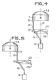
- FIG. 4 is shown another embodiment according to the invention.
- the shock absorber 1 carries on its rear face at an oscillating point, a hinge 21 connected to a hinge 22 by a link 20.
- the hinge 22 is mounted at the diametrical end of a cam 23 fixed on a hinge 230 itself fixed relative to the moving part.
- the cam 23 is in the form of a hollow cylinder ring and carries on its inner face a groove whose shape is calculated according to the principle of the cam 14 of FIGS. 2 or 3.
- This ring is a movable cam which makes it possible to balance the moment of inertia of the moving crew 1-8.
- a bent lever 24, as described in FIG. 3, is fixed to the central axis of the motor 10.
- the bent axis 24 has at its upper end a horizontal part which remains constantly inside the rectilinear slot made in the cam 23.
- the permanent rotational movement of the motor is therefore transformed by means of the cam 23 and of the lever 20 into an alternating oscillation movement around the pivots for the mobile assembly.
- FIG. 5 a variant of FIG. 4 is presented.
- the moving element 1-8 has been rotated 180 ° in the plane of the figure so that the movements of the moving element 1-8 and of the cam 23 are always in opposition.
- This arrangement makes it possible to balance the moments of the couples in particular at the changes of direction of the oscillations. This avoids a jolt on the moving part at each oscillation.
Landscapes
- Health & Medical Sciences (AREA)
- Life Sciences & Earth Sciences (AREA)
- Physics & Mathematics (AREA)
- Pathology (AREA)
- General Health & Medical Sciences (AREA)
- Molecular Biology (AREA)
- Animal Behavior & Ethology (AREA)
- Radiology & Medical Imaging (AREA)
- Engineering & Computer Science (AREA)
- Biomedical Technology (AREA)
- Heart & Thoracic Surgery (AREA)
- Medical Informatics (AREA)
- Biophysics (AREA)
- Surgery (AREA)
- Nuclear Medicine, Radiotherapy & Molecular Imaging (AREA)
- Veterinary Medicine (AREA)
- Public Health (AREA)
- Acoustics & Sound (AREA)
- Chemical & Material Sciences (AREA)
- Analytical Chemistry (AREA)
- Biochemistry (AREA)
- General Physics & Mathematics (AREA)
- Immunology (AREA)
- Ultra Sonic Daignosis Equipment (AREA)
- Investigating Or Analyzing Materials By The Use Of Ultrasonic Waves (AREA)
Applications Claiming Priority (2)
| Application Number | Priority Date | Filing Date | Title |
|---|---|---|---|
| FR8120861A FR2516246A1 (fr) | 1981-11-06 | 1981-11-06 | Sonde ultrasonore a balayage mecanique sectoriel |
| FR8120861 | 1981-11-06 |
Publications (2)
| Publication Number | Publication Date |
|---|---|
| EP0079284A1 EP0079284A1 (fr) | 1983-05-18 |
| EP0079284B1 true EP0079284B1 (fr) | 1986-09-24 |
Family
ID=9263778
Family Applications (1)
| Application Number | Title | Priority Date | Filing Date |
|---|---|---|---|
| EP19820402042 Expired EP0079284B1 (fr) | 1981-11-06 | 1982-11-05 | Sonde ultrasonore à balayage mécanique sectoriel |
Country Status (3)
| Country | Link |
|---|---|
| EP (1) | EP0079284B1 (enExample) |
| DE (1) | DE3273478D1 (enExample) |
| FR (1) | FR2516246A1 (enExample) |
Families Citing this family (8)
| Publication number | Priority date | Publication date | Assignee | Title |
|---|---|---|---|---|
| US4772849A (en) * | 1986-09-11 | 1988-09-20 | Combustion Engineering, Inc. | Rotating probe head for tube inspection |
| DE3842759C2 (de) * | 1988-12-19 | 1997-12-18 | Siemens Ag | Richtscharfer Ultraschall-Wandler mit gekrümmter Abstrahlfläche |
| JPH03280939A (ja) * | 1990-03-29 | 1991-12-11 | Fujitsu Ltd | 超音波探触子 |
| FR2688923B1 (fr) * | 1992-03-23 | 1994-06-10 | Sagem | Dispositif d'entrainement magnetique etanche sans traversee de paroi et sonde ultra-sonore en comportant application. |
| US5373849A (en) * | 1993-01-19 | 1994-12-20 | Cardiovascular Imaging Systems, Inc. | Forward viewing imaging catheter |
| CN100566663C (zh) * | 2007-06-01 | 2009-12-09 | 深圳市德力凯电子有限公司 | 一种脑血流检测探头架 |
| WO2020102993A1 (zh) * | 2018-11-20 | 2020-05-28 | 深圳迈瑞生物医疗电子股份有限公司 | 超声波探头 |
| FR3123442B1 (fr) | 2021-05-26 | 2024-05-10 | Echopen Factory | Sonde échographique et procédé de mise en oeuvre |
Family Cites Families (8)
| Publication number | Priority date | Publication date | Assignee | Title |
|---|---|---|---|---|
| DE1289617B (de) * | 1964-06-06 | 1969-02-20 | Siemens Ag | Ultraschall-Diagnostikgeraet |
| US3741004A (en) * | 1971-02-16 | 1973-06-26 | Automation Ind Inc | Ultrasonic contact scanner |
| GB1539512A (en) * | 1975-01-17 | 1979-01-31 | Greater Glasgow Health Board | Ultrasonic scanning apparatus |
| JPS52130178A (en) * | 1976-04-23 | 1977-11-01 | Tokyo Shibaura Electric Co | Ultrasonic high speed repetition scanning device |
| JPS5615722A (en) * | 1979-07-19 | 1981-02-16 | Olympus Optical Co | Ultrasonic diagnosing device incorporated into endoscope |
| DE2924194C2 (de) * | 1979-06-15 | 1981-07-09 | Siemens AG, 1000 Berlin und 8000 München | Ultraschallgerät für Sektorabtastung |
| AT368866B (de) * | 1980-01-23 | 1982-11-25 | Kretztechnik Gmbh | Ultraschallschnittbildgeraet |
| DE3175444D1 (en) * | 1980-07-29 | 1986-11-13 | Jacques Dory | Probe for echography with sectional mechanical scanning |
-
1981
- 1981-11-06 FR FR8120861A patent/FR2516246A1/fr active Granted
-
1982
- 1982-11-05 DE DE8282402042T patent/DE3273478D1/de not_active Expired
- 1982-11-05 EP EP19820402042 patent/EP0079284B1/fr not_active Expired
Also Published As
| Publication number | Publication date |
|---|---|
| FR2516246B1 (enExample) | 1985-05-17 |
| DE3273478D1 (en) | 1986-10-30 |
| FR2516246A1 (fr) | 1983-05-13 |
| EP0079284A1 (fr) | 1983-05-18 |
Similar Documents
| Publication | Publication Date | Title |
|---|---|---|
| EP0045265B1 (fr) | Sonde d'échographie à balayage sectoriel mécanique | |
| EP0079284B1 (fr) | Sonde ultrasonore à balayage mécanique sectoriel | |
| FR2512905A1 (fr) | Suspension a deux dimensions | |
| BE1010513A4 (fr) | Plate-forme asservie et stabilisee perfectionnee. | |
| FR2537301A1 (fr) | Convertisseur electro-mecanique a plusieurs degres de liberte | |
| FR2755799A1 (fr) | Mecanisme a bagues collectrices | |
| FR2607315A1 (fr) | Organe electromagnetique de commande | |
| FR2688923A1 (fr) | Dispositif d'entrainement magnetique etanche sans traversee de paroi et sonde ultra-sonore en comportant application. | |
| FR2634956A1 (fr) | Dispositif pour appliquer un mouvement de balayage ou d'oscillation a un element et methode s'y rapportant | |
| FR2516272A1 (fr) | Scanographe a ultrasons | |
| CH407345A (fr) | Appareil pour vérifier les caractéristiques ou la position d'un faisceau de particules chargées | |
| EP2706267A1 (fr) | Dispositif de positionnement angulaire comprenant deux ensembles mécaniques de transmission de mouvement imbriqués à deux points morts chacun | |
| FR2547409A1 (fr) | Compensateur d'oscillations pour gyroscope a laser en anneau | |
| EP0056550B1 (fr) | Dispositif d'orientation selon deux axes orthogonaux, en particulier pour une antenne hyperfréquence | |
| EP0098202B1 (fr) | Sonde à ultrasons et installation d'échographie utilisant une telle sonde | |
| US3888562A (en) | Oscillating scanner | |
| FR2519458A1 (fr) | Tete optique notamment pour la lecture d'une information | |
| CN111175765A (zh) | 一种双轴承振镜和激光雷达 | |
| FR2463949A1 (fr) | Appareil de mise en position reperee d'un capteur gyroscopique | |
| FR3035186A1 (fr) | Dispositif d'eclairage medical | |
| FR2525460A1 (fr) | Sonde corporelle a faisceau oscillant | |
| EP0961151B1 (fr) | Actionneur optique permettant d'amener un faisceau de lumière incidente sur une surface fixe extérieure audit actionneur | |
| FR2614413A1 (fr) | Gyrometre laser, dispositif d'elimination des rotations parasites des miroirs piezoelectriques utilisant les forces d'inertie | |
| EP0519051B1 (fr) | Capteur de vibrations suivant deux directions orthogonales | |
| EP1738094B1 (fr) | Mecanisme d'entrainement utilisable dans un dispositif de balayage |
Legal Events
| Date | Code | Title | Description |
|---|---|---|---|
| PUAI | Public reference made under article 153(3) epc to a published international application that has entered the european phase |
Free format text: ORIGINAL CODE: 0009012 |
|
| AK | Designated contracting states |
Designated state(s): BE CH DE GB LI |
|
| 17P | Request for examination filed |
Effective date: 19831007 |
|
| RBV | Designated contracting states (corrected) |
Designated state(s): DE GB |
|
| GRAA | (expected) grant |
Free format text: ORIGINAL CODE: 0009210 |
|
| AK | Designated contracting states |
Kind code of ref document: B1 Designated state(s): DE GB |
|
| REF | Corresponds to: |
Ref document number: 3273478 Country of ref document: DE Date of ref document: 19861030 |
|
| PLBI | Opposition filed |
Free format text: ORIGINAL CODE: 0009260 |
|
| GBPC | Gb: european patent ceased through non-payment of renewal fee | ||
| 26 | Opposition filed |
Opponent name: SIEMENS AKTIENGESELLSCHAFT, BERLIN UND MUENCHEN Effective date: 19870622 |
|
| PG25 | Lapsed in a contracting state [announced via postgrant information from national office to epo] |
Ref country code: DE Effective date: 19880801 |
|
| PG25 | Lapsed in a contracting state [announced via postgrant information from national office to epo] |
Ref country code: GB Effective date: 19881121 |
|
| PLBN | Opposition rejected |
Free format text: ORIGINAL CODE: 0009273 |
|
| STAA | Information on the status of an ep patent application or granted ep patent |
Free format text: STATUS: OPPOSITION REJECTED |
|
| 27O | Opposition rejected |
Effective date: 19900611 |
|
| APAH | Appeal reference modified |
Free format text: ORIGINAL CODE: EPIDOSCREFNO |