EP0056550B1 - Dispositif d'orientation selon deux axes orthogonaux, en particulier pour une antenne hyperfréquence - Google Patents
Dispositif d'orientation selon deux axes orthogonaux, en particulier pour une antenne hyperfréquence Download PDFInfo
- Publication number
- EP0056550B1 EP0056550B1 EP81402051A EP81402051A EP0056550B1 EP 0056550 B1 EP0056550 B1 EP 0056550B1 EP 81402051 A EP81402051 A EP 81402051A EP 81402051 A EP81402051 A EP 81402051A EP 0056550 B1 EP0056550 B1 EP 0056550B1
- Authority
- EP
- European Patent Office
- Prior art keywords
- axis
- transmission means
- pinion
- fixed
- orientation device
- Prior art date
- Legal status (The legal status is an assumption and is not a legal conclusion. Google has not performed a legal analysis and makes no representation as to the accuracy of the status listed.)
- Expired
Links
- 230000007246 mechanism Effects 0.000 claims description 29
- 230000005540 biological transmission Effects 0.000 claims description 15
- 230000007704 transition Effects 0.000 description 1
- 230000001960 triggered effect Effects 0.000 description 1
Images

Classifications
-
- H—ELECTRICITY
- H01—ELECTRIC ELEMENTS
- H01Q—ANTENNAS, i.e. RADIO AERIALS
- H01Q3/00—Arrangements for changing or varying the orientation or the shape of the directional pattern of the waves radiated from an antenna or antenna system
- H01Q3/02—Arrangements for changing or varying the orientation or the shape of the directional pattern of the waves radiated from an antenna or antenna system using mechanical movement of antenna or antenna system as a whole
- H01Q3/08—Arrangements for changing or varying the orientation or the shape of the directional pattern of the waves radiated from an antenna or antenna system using mechanical movement of antenna or antenna system as a whole for varying two co-ordinates of the orientation
-
- Y—GENERAL TAGGING OF NEW TECHNOLOGICAL DEVELOPMENTS; GENERAL TAGGING OF CROSS-SECTIONAL TECHNOLOGIES SPANNING OVER SEVERAL SECTIONS OF THE IPC; TECHNICAL SUBJECTS COVERED BY FORMER USPC CROSS-REFERENCE ART COLLECTIONS [XRACs] AND DIGESTS
- Y10—TECHNICAL SUBJECTS COVERED BY FORMER USPC
- Y10T—TECHNICAL SUBJECTS COVERED BY FORMER US CLASSIFICATION
- Y10T74/00—Machine element or mechanism
- Y10T74/19—Gearing
- Y10T74/19014—Plural prime movers selectively coupled to common output
-
- Y—GENERAL TAGGING OF NEW TECHNOLOGICAL DEVELOPMENTS; GENERAL TAGGING OF CROSS-SECTIONAL TECHNOLOGIES SPANNING OVER SEVERAL SECTIONS OF THE IPC; TECHNICAL SUBJECTS COVERED BY FORMER USPC CROSS-REFERENCE ART COLLECTIONS [XRACs] AND DIGESTS
- Y10—TECHNICAL SUBJECTS COVERED BY FORMER USPC
- Y10T—TECHNICAL SUBJECTS COVERED BY FORMER US CLASSIFICATION
- Y10T74/00—Machine element or mechanism
- Y10T74/19—Gearing
- Y10T74/19023—Plural power paths to and/or from gearing
- Y10T74/19051—Single driven plural drives
- Y10T74/1906—Nonparallel
-
- Y—GENERAL TAGGING OF NEW TECHNOLOGICAL DEVELOPMENTS; GENERAL TAGGING OF CROSS-SECTIONAL TECHNOLOGIES SPANNING OVER SEVERAL SECTIONS OF THE IPC; TECHNICAL SUBJECTS COVERED BY FORMER USPC CROSS-REFERENCE ART COLLECTIONS [XRACs] AND DIGESTS
- Y10—TECHNICAL SUBJECTS COVERED BY FORMER USPC
- Y10T—TECHNICAL SUBJECTS COVERED BY FORMER US CLASSIFICATION
- Y10T74/00—Machine element or mechanism
- Y10T74/20—Control lever and linkage systems
- Y10T74/20207—Multiple controlling elements for single controlled element
Definitions
- the present invention relates to a steering device of a driven member along two orthogonal axes of rotation and more particularly to a steering device p Ol, r sings hyperfré- .quence.
- each orientation axis has a motor mechanism which actuates a platform carrying the following orientation axis and its motor.
- the present invention aims to remedy the above drawbacks by proposing an orientation device along two orthogonal axes with which the positioning in azimuth and in elevation can be carried out simultaneously with a single motor.
- the claimed device also has the advantage of releasing a large useful volume thanks to the offset of the motor mechanisms in the fixed part.
- the present invention relates to a device for orienting an element driven along two orthogonal axes
- a device for orienting an element driven along two orthogonal axes comprising a fixed support, a mobile support that can rotate around one of the axes known as the first axis and supporting the driven element by coaxial arms with the other axis called the second axis and decoupled from the mobile support, two motor mechanisms positioned in the fixed part capable of giving movements along each of the axes, characterized in that one of the motor mechanisms controls a transmission means giving simultaneous movement of rotation around each axis and the other motor mechanism controls a set of transmission means giving only a rotational movement around the second axis.
- FIG. 1 represents a perspective view of a device of the prior art used to orient a radar antenna.
- the motor 31 drives a pinion (not visible in the figure) which meshes with the toothed part 33 of a part 34 supporting the motor 32 and a toothed wheel 35.
- the motor 32 drives a pinion 36 which meshes the toothed wheel 35.
- On the outside diameter of the latter is fixed at its top a piece 37 in the form of a V at the two ends of which is articulated a rod 40 and 41 respectively, the other end of which is articulated on a point of the surface. of the antenna 42 to be oriented.
- the latter is also held in its center by a part 38 which can pivot relative to the part 34 around the articulation 39.
- the two motors 31 and 32 therefore make it possible to orient the antenna 42 by making it pivot relative to two axes, respectively the axis 43 by pivoting of the part 34 around the articulation 39 and the axis 44 by pivoting of the part 37 therefore of the wheel 35. But the circular movement of the antenna around the axis 43 is slowed down by the inertia of the weight of the motor 32.
- the present invention overcomes this drawback.
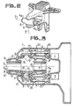
- FIG. 3 represents a side view in section of FIG. 2, after having made the structure 8 rotate by 90 ° around the axis 3.
- the arm 1 of the fixed part houses the motor mechanism 1 controlling the so-called circular movement of the system to be oriented.
- This mechanism is connected to a transmission shaft 6 placed inside the arm 1 and decoupled therefrom using means 20.
- the opposite end of the transmission shaft 6 acts on a conical torque formed by a pinion 17, disposed at the end of the shaft 6, and a toothed wheel 18 of axis 3 orthogonal to that of the pinion 17 and the shaft 6.
- This wheel 18 is placed inside the arm 1 and is connected through the wall of the arm 1 to the structure 8 via the cylindrical part 21 forming one of the points of articulation of the structure 8 with the fixed part.
- This cylindrical part 21 is decoupled by means 10 from the wall of the arm 1 which it passes through.
- a cylindrical part formed by two distinct hollow parts 4a and 4b of cylindrical shape, situated on either side of the axis 3. These two parts 4a and 4b have a common axis 5 with the external structure 8 from which they are decoupled by means 9.
- the arm 2 of the C-shaped fixed part houses the motor mechanism II controlling the so-called elevation movement of the system to be oriented.
- This mechanism is connected to a transmission shaft 7 placed inside the arm 2 and decoupled therefrom by means 20.
- the opposite end of the shaft 7 acts on a conical couple housed by the arm 2 and formed by a pinion 13 disposed at the end of the shaft 7 and a toothed wheel 14 of axis 3.
- the first bevel couple drives, by means of a cylindrical part 19 of axis 3, a second bevel couple arranged inside the structure 8 and comprising a toothed wheel 15 of axis 3 coming to mesh with a toothed wheel 16 of axis 5 placed at the periphery of the cylindrical part 4a.
- the cylindrical transition piece 19 passes through the wall of the arm 2 and of the structure 8, with respect to which it is decoupled by means 11 and 12.
- the system to be oriented is fixed at A, B and A ', B' on the cylindrical parts 4a and 4b respectively, outside the structure 8. It constitutes the second branch of the gimbal.
- the motor It rotates, by means of the shaft 7 provided with the pinion 13, the toothed wheel 14 therefore the wheel 15 coupled by the cylindrical part 19.
- the wheel 15 comes to mesh the wheel 16 and rotates the piece 4a around the axis 5.
- the system fixed to this piece 4a also pivots around this axis and in its movement drives the piece 4b in synchronism. But the parts 4a and 4b being decoupled from the structure 8, the latter remains stationary.
- the motor rotates, via the shaft 6 provided with the pinion 17, the toothed wheel 18 around the axis 3 and therefore the structure 8 to which it is fixed, as well as the parts 4a and 4b arranged inside the structure, and therefore the system to be oriented. It is the circular movement around the axis 3.
- the structure 8 is decoupled, by means 11, from the cylindrical part 19, and the latter and therefore the wheel 15 which is fixed to it, are stationary since the motor mechanism It is not powered.
- the wheel 16 As the part 4a and therefore the wheel 16 rotate around the axis 3, given the circular movement of the structure 8, the wheel 16 must move along the toothed wheel 15 of axis 3 with which it is in contact, which causes the rotation of the part 4a around the axis 5 and consequently that of the system to be oriented and that of the part 4b. It is the movement in elevation around axis 5.
- Means such as gyrometers or annular digital encoders arranged between fixed parts and mobile parts make it possible to know and measure the movements in circular and elevation which makes it possible to control the motor mechanisms accordingly. It is possible to cancel the elevation movement when the motor mechanism of the circular movement 1 is supplied. Indeed, it suffices to simultaneously control, via the motor mechanism II, the toothed wheel 15 of the same angular quantity as the toothed wheel 18 in order to neutralize the relative movement of the two wheels 16 and 15.
- the motor mechanisms can be geared motors.
- the decoupling means 9, 10, 11, 12, 20 are for example ball bearings.
- the device according to the invention can be used in particular for orienting a microwave antenna. Indeed, such an antenna must be able to be oriented quickly along two axes;
- the motor mechanisms occupy in the mobile parts a certain volume which could be used more advantageously for accommodating microwave rotary joints therein.
- the microwave receiver is placed in this case as close as possible to the antenna. It is therefore generally attached to the back of the antenna and is subjected to very strong vibrations. De-plus it gives additional inertia during antenna movements and the motors, on moving parts, limit the strikes of antenna travel.
- the motor mechanisms being installed on fixed parts, allow significant antenna deflections.
- they release the volume located in the center of the gimbal in favor of rotating joints, thus allowing the microwave receiver to be moved to a fixed part where the vibration environment is less severe.
Landscapes
- Variable-Direction Aerials And Aerial Arrays (AREA)
Description
- La présente invention concerne un dispositif d'orientation d'un élément mené selon deux axes de rotation orthogonaux et plus particulièrement un dispositif d'orientation pOl,r entonne hyperfré- .quence.
- Pour orienter des systèmes particulièrement lourds ou pour augmenter la vitesse d'orientation, il est nécessaire d'utiliser des mécanismes moteurs de plus en plus puissants et de minimiser la masse des parties en mouvement.
- Dans les dispositifs d'orientation connus, chaque axe d'orientation possède un mécanisme moteur qui actionne une plate-forme portant l'axe d'orientation suivant et son moteur. L'utilisation de mécanismes moteurs plus puissants, donc plus lourds, freine ces mouvements, certains mécanismes étant placés sur des parties mobiles.
- On a déjà proposé, notamment dans le brevet US 2.930.255, un dispositif d'orientation selon deux axes orthogonaux, dans lequel les mécanismes moteurs sont installés sur des parties fixes. Dans ce cas toutefois, le positionnement en azimuth et le positionnement en élévation sont toujours effectués séparément.
- La présente invention a pour but de remédier aux inconvénients ci-dessus en proposant un dispositif d'orientation selon deux axes orthogonaux avec lequel le positionnement en azimuth et en élévation peut être réalisé simultanément avec un seul moteur.
- D'autre part, le dispositif revendiqué a également pour avantage de libérer un volume utile important grâce au déport des mécanismes moteurs en partie fixe.
- La présente invention a pour objet un dispositif d'orientation d'un élément mené selon deux axes orthogonaux comportant un support fixe, un support mobile pouvant tourner autour d'un des axes dit premier axe et supportant l'élément mené par des bras coaxiaux avec l'autre axe dit second axe et découplés du support mobile, deux mécanismes moteurs positionnés dans la partie fixe susceptible de donner des mouvements selon chacun des axes, caractérisé en ce que l'un des mécanismes moteurs commande un moyen de transmission donnant simultanément un mouvement de rotation autour de chaque axe et l'autre mécanisme moteur commande un ensemble de moyens de transmission donnant uniquement un mouvement de rotation autour du second axe.
- D'autres caractéristiques et avantages de la présente invention apparaîtront à la lecture de la description détaillée faite ci-aprés avec référence aux figures ci-annexées qui représentent:
- Figure 1, une vue en perspective d'un dispositif d'orientation de l'art antérieur;
- Figure 2, une vue en perspective du dispositif d'orientation selon l'invention;
- Figure 3, une vue latérale en coupe du dispositif de la figure 2.
- La figure 1 représente une vue en perspective d'un dispositif de l'art antérieur utilisé pour orienter une antenne de radar. Dans ce dispositif, le moteur 31 entraîne un pignon (non visible sur la figure) qui engrène la partie dentée 33 d'une pièce 34 supportant le moteur 32 et une roue dentée 35. Le moteur 32 entraîne un pignon 36 qui engrène la roue dentée 35. Sur le diamètre extérieur de celle-ci est fixée en son sommet une pièce 37 en forme de V aux deux extrémités de laquelle est articulée une tige respectivement 40 et 41 dont l'autre extrémité vient s'articuler sur un point de la surface de l'antenne 42 à orienter. Celle-ci est également maintenue en son centre par une pièce 38 pouvant pivoter par rapport à la partie 34 autour de l'articulation 39.
- Les deux moteurs 31 et 32 permettent donc d'orienter l'antenne 42 en la faisant pivoter par rapport à deux axes, respectivement l'axe 43 par pivotement de la pièce 34 autour de l'articulation 39 et l'axe 44 par pivotement de la pièce 37 donc de la roue 35. Mais le déplacement circulaire de l'antenne autour de l'axe 43 est freiné par l'inertie du poids du moteur 32.
- La présente invention permet de remédier à cet inconvénient.
- Le dispositif selon l'invention, dont une vue générale est représentée en perspective en figure 2, comprend une partie fixe en forme de C allongé dont les deux bras 1, 2 forment la première branche du cardan, et une partie mobile 4a, 4b, 8 formant la noix du cardan dont l'axe longitudinal 5 constitue l'un des deux axes d'orientation. Cette noix de cardan se compose d'une partie cylindrique 4a, 4b et d'une structure extérieure 8 coaxiale dont la partie 4a, 4b est découplée et à l'intérieur de laquelle elle peut pivoter autour de l'axe longitudinal commun 5. La structure 8 peut elle-même pivoter autour de l'axe 3 orthogonal à l'axe 5, entre les bras 1 et 2 de la partie fixe.
- La figure 3 représente une vue latérale en coupe de la figure 2, après avoir fait pivoter la structure 8 de 90° autour de l'axe 3.
- Le bras 1 de la partie fixe abrite le mécanisme moteur 1 commandant le mouvement dit circulaire du système à orienter. Ce mécanisme est raccordé à un arbre de transmission 6 placé à l'intérieur du bras 1 et découplé de cellui-ci à l'aide de moyens 20. L'extrémité opposée de l'arbre de transmission 6 agit sur un couple conique formé par un pignon 17, disposé à l'extrémité de l'arbre 6, et une roue dentée 18 d'axe 3 orthogonal à celui du pignon 17 et de l'arbre 6. Cette roue 18 est placée à l'intérieur du bras 1 et est raccordée à travers la paroi du bras 1 à la structure 8 par l'intermédiaire de la partie cylindrique 21 formant un des points d'articulation de la structure 8 avec la partie fixe. Cette partie cylindrique 21 est découplée par des moyens 10 de la paroi du bras 1 qu'elle traverse. A l'intérieur de la structure 8 est disposée une partie cylindrique formée de deux parties distinctes creuses 4a et 4b de forme cylindrique, situées de part et d'autre de l'axe 3. Ces deux parties 4a et 4b ont un axe commun 5 avec la structure extérieure 8 dont elles sont découplées par des moyens 9.
- Le bras 2 de la partie fixe en forme de C abrite le mécanisme moteur II commandant le mouvement dit en élévation du système à orienter. Ce mécanisme est raccordé à un arbre de transmission 7 placé à l'intérieur du bras 2 et découplé de celui-ci par des moyens 20. L'extrémité opposée de l'arbre 7 agit sur un couple conique abrité par le bras 2 et formé par un pignon 13 disposé à l'extrémité de l'arbre 7 et une roue dentée 14 d'axe 3. Le premier couple conique attaque, par l'intermédiaire d'une partie cylindrique 19 d'axe 3, un deuxième couple conique disposé à l'intérieur de la structure 8 et comprenant une roue dentée 15 d'axe 3 venant engrener une roue dentée 16 d'axe 5 placée à la périphérie de la partie cylindrique 4a. La pièce cylindrique de transition 19 traverse la paroi du bras 2 et de la structure 8, par rapport à laquelle elle est découplée par des moyens 11 et 12.
- Le système à orienter, non représenté, est fixé en A, B et A', B' sur les parties cylindriques 4a et 4b respectivement, à l'extérieur de la structure 8. Il constitue la deuxième branche du cardan.
- Si on alimente le mécanisme moteur Il seul on déclenche uniquement le mouvement dit en élévation autour de l'axe 5.
- En effet, le moteur Il fait tourner, par l'intermédiaire de l'arbre 7 muni du pignon 13, la roue dentée 14 donc la roue 15 couplées par la partie cylindrique 19. La roue 15 vient engréner la roue 16 et fait tourner la pièce 4a autour de l'axe 5. Le système fixé à cette pièce 4a pivote également autour de cet axe et entraîne dans son mouvement la pièce 4b en synchronisme. Mais les pièces 4a et 4b étant découplées de la structure 8, celle-ci reste immobile.
- - Il ne se produit donc qu'un mouvement en élévation.
- Si par contre on alimente le mécanisme moteur 1 seul, il se produit à la fois un mouvement en circulaire autour de l'axe 3 et un mouvement en élévation autour de l'axe 5.
- En effet, le moteur fait tourner, par l'intermédiaire de l'arbre 6 muni du pignon 17, la roue dentée 18 autour de l'axe 3 et par conséquent la structure 8 à laquelle elle est fixée, ainsi que les parties 4a et 4b disposées à l'intérieur de la structure, et donc le système à orienter. C'est le mouvement en circulaire autour de l'axe 3. Or la structure 8 est découplée, par des moyens 11, de la partie cylindrique 19, et celle-ci et donc la roue 15 qui lui est fixée, sont immobiles puisque le mécanisme moteur Il n'est pas alimenté. Comme la partie 4a et donc la roue 16 tournent autour de l'axe 3, étant donné le mouvement en circulaire de la structure 8, la roue 16 doit se déplacer le long de la roue dentée 15 d'axe 3 avec laquelle elle est en contact, ce qui provoque la rotation de la partie 4a autour de l'axe 5 et par conséquent celle du système à orienter et celle de la partie 4b. C'est le mouvement en élévation autour de l'axe 5.
- Des moyens tels que des gyromètres ou des codeurs numériques annulaires disposés entre parties fixes et parties mobiles permettent de connaître et de mesurer les mouvements en circulaire et en élévation ce qui permet de commander les mécanismes moteurs en conséquence. Il est possible d'annuler le mouvement en élévation lorsque le mécanisme moteur du mouvement en circulaire 1 est alimenté. En effet, il suffit de commander simultanément, par l'intermédiaire du mécanisme moteur Il la roue dentée 15 de la même quantité angulaire que la roue dentée 18 afin de neutraliser le mouvement relatif des deux roues 16 et 15.
- Selon un mode de réalisation préférentiel, les mécanismes moteurs peuvent être des moto- réducteurs.
- Les moyens de découplage 9,10,11,12,20 sont par exemple des roulements à billes.
- Le dispositif selon l'invention peut être utilisé en particulier pour orienter une antenne hyperfréquence. En effet, une telle antenne doit pouvoir être orientée rapidement suivant deux axes; Quand on utilise un dispositif d'orientation de l'art antérieur, les mécanismes moteurs occupent dans les parties mobiles un certain volume qui pourrait être utilisé plus avantageusement pour y loger des joints tournants hyperfréquence. Etant donné le manque de place pour les joints tournants, le récepteur hyperfréquence est disposé dans ce cas le plus près possible de l'antenne. Il est donc en général accolé au dos de l'antenne et est soumis à de très fortes vibrations. De-plus il donne une inertie supplémentaire lors des mouvements d'antenne et les moteurs, sur parties mobiles, limitent les épures de débattement d'antenne.
- Grâce au dispositif d'orientation selon la présente invention, les mécanismes moteurs, étant installés sur des parties fixes, permettent des débattements d'antenne importants. De plus, ils libèrent le volume situé au centre du cardan au profit de joints tournants permettant ainsi de déporter le récepteur hyperfréquence en partie fixe où l'environnement vibratoire est moins sévère.
- Les applications de ce dispositif ne sont pas limitées à l'exemple précité mais s'étend à tous les cas de deux mouvements orthogonaux portés l'un par l'autre et où les mécanismes moteurs doivent, de préférence, être en partie fixe.
Claims (8)
Applications Claiming Priority (2)
| Application Number | Priority Date | Filing Date | Title |
|---|---|---|---|
| FR8100946 | 1981-01-20 | ||
| FR8100946A FR2498379A1 (fr) | 1981-01-20 | 1981-01-20 | Dispositif d'orientation selon deux axes orthogonaux, utilisation dans une antenne hyperfrequence et antenne hyperfrequence comportant un tel dispositif |
Publications (3)
| Publication Number | Publication Date |
|---|---|
| EP0056550A2 EP0056550A2 (fr) | 1982-07-28 |
| EP0056550A3 EP0056550A3 (en) | 1982-08-11 |
| EP0056550B1 true EP0056550B1 (fr) | 1985-04-17 |
Family
ID=9254312
Family Applications (1)
| Application Number | Title | Priority Date | Filing Date |
|---|---|---|---|
| EP81402051A Expired EP0056550B1 (fr) | 1981-01-20 | 1981-12-22 | Dispositif d'orientation selon deux axes orthogonaux, en particulier pour une antenne hyperfréquence |
Country Status (4)
| Country | Link |
|---|---|
| US (1) | US4491847A (fr) |
| EP (1) | EP0056550B1 (fr) |
| DE (1) | DE3170061D1 (fr) |
| FR (1) | FR2498379A1 (fr) |
Families Citing this family (9)
| Publication number | Priority date | Publication date | Assignee | Title |
|---|---|---|---|---|
| US4692771A (en) * | 1985-03-28 | 1987-09-08 | Satellite Technology Services, Inc. | Antenna dish reflector with integral azimuth track |
| US4716416A (en) * | 1985-03-28 | 1987-12-29 | Satellite Technology Services, Inc. | Antenna dish reflector with integral declination adjustment |
| US5077560A (en) * | 1986-02-19 | 1991-12-31 | Sts Enterprises, Inc. | Automatic drive for a TVRO antenna |
| FR2685081B1 (fr) * | 1991-12-11 | 1994-02-04 | Thomson Csf | Structure a controle d'endommagement intrinseque, procede de fabrication et methode d'utilisation. |
| CA2577444C (fr) * | 1996-06-27 | 2009-11-24 | Interdigital Technology Corporation | Utilisation de codes courts pour lineariser la montee en puissance initiale des systemes amdc |
| US5769748A (en) * | 1997-01-16 | 1998-06-23 | Hughes Electronics Corporation | Gimbal employing differential combination of offset drives |
| US6478434B1 (en) | 1999-11-09 | 2002-11-12 | Ball Aerospace & Technologies Corp. | Cryo micropositioner |
| GB2505066A (en) * | 2012-06-27 | 2014-02-19 | Sub10 Systems Ltd | Positioning gear, bracket and system having gear segments |
| US11901606B1 (en) * | 2020-01-09 | 2024-02-13 | Space Exploration Technologies Corp. | Pan/tilt assembly for antenna apparatus |
Family Cites Families (8)
| Publication number | Priority date | Publication date | Assignee | Title |
|---|---|---|---|---|
| US2410827A (en) * | 1943-06-28 | 1946-11-12 | Sperry Gyroscope Co Inc | Scanning device |
| US2651721A (en) * | 1946-03-22 | 1953-09-08 | Sperry Corp | Antenna apparatus |
| NL173647B (nl) * | 1951-11-08 | Naphtachimie Sa | Werkwijze voor de bereiding van katalysatoren voor de polymerisatie van alkenen, werkwijze voor de bereiding van polymeren of copolymeren en gevormde voortbrengselen, vervaardigd onder toepassing van de aldus bereide polymeren of copolymeren. | |
| US2980255A (en) * | 1958-03-04 | 1961-04-18 | Bernhard M Aagaard | Method and apparatus for the grading of coffee beans |
| US2930255A (en) * | 1958-11-28 | 1960-03-29 | Thompson Ramo Wooldridge Inc | Dual drive transmissions |
| GB1186424A (en) * | 1967-03-28 | 1970-04-02 | Marconi Co Ltd | Improvements in or relating to Aerial Drive Mechanisms |
| CH622129A5 (fr) * | 1977-09-30 | 1981-03-13 | Bbc Brown Boveri & Cie | |
| US4238802A (en) * | 1978-12-18 | 1980-12-09 | General Dynamics Corporation, Pomona Division | Differential drive rolling arc gimbal |
-
1981
- 1981-01-20 FR FR8100946A patent/FR2498379A1/fr active Granted
- 1981-12-22 EP EP81402051A patent/EP0056550B1/fr not_active Expired
- 1981-12-22 DE DE8181402051T patent/DE3170061D1/de not_active Expired
-
1982
- 1982-01-20 US US06/341,119 patent/US4491847A/en not_active Expired - Fee Related
Also Published As
| Publication number | Publication date |
|---|---|
| FR2498379B1 (fr) | 1984-10-19 |
| US4491847A (en) | 1985-01-01 |
| EP0056550A3 (en) | 1982-08-11 |
| FR2498379A1 (fr) | 1982-07-23 |
| DE3170061D1 (en) | 1985-05-23 |
| EP0056550A2 (fr) | 1982-07-28 |
Similar Documents
| Publication | Publication Date | Title |
|---|---|---|
| EP0056550B1 (fr) | Dispositif d'orientation selon deux axes orthogonaux, en particulier pour une antenne hyperfréquence | |
| EP0205376B1 (fr) | Tête articulée pour robot industriel et robot équipé d'une telle tête | |
| EP3956219B1 (fr) | Dispositif de propulsion pour aérodyne à voilure tournante et à décollage et atterrissage verticaux, et aérodyne comprenant au moins un tel dispositif de propulsion | |
| EP0153884A1 (fr) | Bras de manipulation modulaire | |
| FR2593106A1 (fr) | Dispositif de deplacement d'un outil ou analogue en porte-a-faux, notamment autour d'un objet. | |
| FR2761286A1 (fr) | Positionneur multiaxe | |
| EP2706267B1 (fr) | Dispositif de positionnement angulaire comprenant deux ensembles mécaniques de transmission de mouvement imbriqués à deux points morts chacun | |
| EP3543588B1 (fr) | Dispositif de positionnement angulaire | |
| FR2539346A1 (fr) | Dispositif manipulateur automatique articule notamment pour le soudage a l'arc | |
| FR2563141A1 (fr) | Mecanisme articule formant un poignet pour robot | |
| FR2774056A1 (fr) | Systeme de direction pour vehicule automobile | |
| EP0188164A1 (fr) | Bloc de direction de véhicule automobile, comportant un coussin central fixe | |
| FR2653219A1 (fr) | Detecteur et procede de detection de verticalite, et base de maintien d'attitude d'un appareil. | |
| FR2504051A1 (fr) | Tete articulee pour robot industriel | |
| FR2704050A1 (fr) | Système de support orientable d'un équipement de mission monté sur un porteur fixe ou mobile. | |
| EP0007861B1 (fr) | Dispositif de réglage d'un rétroviseur notamment pour véhicule | |
| CA2060773C (fr) | Dispositif de support et d'entrainement en rotation d'une charge utile par rapport a une structure, notamment pour un mecanisme de pointage d'antenne de satellite | |
| FR2490335A1 (fr) | Horizon artificiel pour aeronef | |
| WO2022238421A1 (fr) | Dispositif de transmission et de transformation de mouvement et vehicule equipe d'un tel dispositif | |
| EP1582326B1 (fr) | Mécanisme pour bras de support de convoyeur et ensemble de bras de support équipé d'un tel mécanisme | |
| EP0084482B1 (fr) | Télémanipulateur téléscopique du type maître-esclave et ses moyens d'équilibrage | |
| EP3839604B1 (fr) | Dispositif de scan à excentrique amélioré | |
| EP0455543B1 (fr) | Dispositif de pointage d'un réflecteur d'antenne | |
| EP0465582A1 (fr) | Dispositif d'entrainement de la roue avant d'une motocyclette a deux roues motrices et la motocyclette associee | |
| FR2503461A1 (fr) | Dispositif telecommande d'orientation d'antenne |
Legal Events
| Date | Code | Title | Description |
|---|---|---|---|
| PUAI | Public reference made under article 153(3) epc to a published international application that has entered the european phase |
Free format text: ORIGINAL CODE: 0009012 |
|
| PUAL | Search report despatched |
Free format text: ORIGINAL CODE: 0009013 |
|
| AK | Designated contracting states |
Designated state(s): DE GB IT |
|
| AK | Designated contracting states |
Designated state(s): DE GB IT |
|
| 17P | Request for examination filed |
Effective date: 19820827 |
|
| ITF | It: translation for a ep patent filed | ||
| GRAA | (expected) grant |
Free format text: ORIGINAL CODE: 0009210 |
|
| AK | Designated contracting states |
Designated state(s): DE GB IT |
|
| REF | Corresponds to: |
Ref document number: 3170061 Country of ref document: DE Date of ref document: 19850523 |
|
| PLBE | No opposition filed within time limit |
Free format text: ORIGINAL CODE: 0009261 |
|
| STAA | Information on the status of an ep patent application or granted ep patent |
Free format text: STATUS: NO OPPOSITION FILED WITHIN TIME LIMIT |
|
| 26N | No opposition filed | ||
| PGFP | Annual fee paid to national office [announced via postgrant information from national office to epo] |
Ref country code: GB Payment date: 19911122 Year of fee payment: 11 Ref country code: DE Payment date: 19911122 Year of fee payment: 11 |
|
| ITTA | It: last paid annual fee | ||
| PG25 | Lapsed in a contracting state [announced via postgrant information from national office to epo] |
Ref country code: GB Effective date: 19921222 |
|
| GBPC | Gb: european patent ceased through non-payment of renewal fee |
Effective date: 19921222 |
|
| PG25 | Lapsed in a contracting state [announced via postgrant information from national office to epo] |
Ref country code: DE Effective date: 19930901 |