EP0079279B1 - Procédé pour l'ouverture aseptique et anti-particulaire d'enceintes en verre scellé et dispositif et appareil mettant en oeuvre ce procédé - Google Patents
Procédé pour l'ouverture aseptique et anti-particulaire d'enceintes en verre scellé et dispositif et appareil mettant en oeuvre ce procédé Download PDFInfo
- Publication number
- EP0079279B1 EP0079279B1 EP82402029A EP82402029A EP0079279B1 EP 0079279 B1 EP0079279 B1 EP 0079279B1 EP 82402029 A EP82402029 A EP 82402029A EP 82402029 A EP82402029 A EP 82402029A EP 0079279 B1 EP0079279 B1 EP 0079279B1
- Authority
- EP
- European Patent Office
- Prior art keywords
- ampul
- glass
- opening
- station
- melting
- Prior art date
- Legal status (The legal status is an assumption and is not a legal conclusion. Google has not performed a legal analysis and makes no representation as to the accuracy of the status listed.)
- Expired
Links
- 239000011521 glass Substances 0.000 title claims description 40
- 238000000034 method Methods 0.000 title claims description 27
- 230000008569 process Effects 0.000 title description 9
- 239000002245 particle Substances 0.000 title description 2
- 239000003708 ampul Substances 0.000 claims description 37
- 238000002844 melting Methods 0.000 claims description 19
- 230000008018 melting Effects 0.000 claims description 19
- 230000036512 infertility Effects 0.000 claims description 15
- 230000033001 locomotion Effects 0.000 claims description 15
- 238000012360 testing method Methods 0.000 claims description 14
- 238000010438 heat treatment Methods 0.000 claims description 11
- 125000001475 halogen functional group Chemical group 0.000 claims description 9
- 230000004907 flux Effects 0.000 claims description 8
- 239000000470 constituent Substances 0.000 claims description 2
- 239000000047 product Substances 0.000 claims 2
- 239000012263 liquid product Substances 0.000 claims 1
- 239000012265 solid product Substances 0.000 claims 1
- 239000007789 gas Substances 0.000 description 8
- 238000005070 sampling Methods 0.000 description 8
- 230000009471 action Effects 0.000 description 6
- 230000008901 benefit Effects 0.000 description 4
- 230000004927 fusion Effects 0.000 description 3
- 239000000203 mixture Substances 0.000 description 3
- 230000035939 shock Effects 0.000 description 3
- 241001639412 Verres Species 0.000 description 2
- 230000001276 controlling effect Effects 0.000 description 2
- 238000004519 manufacturing process Methods 0.000 description 2
- 239000006060 molten glass Substances 0.000 description 2
- 238000009527 percussion Methods 0.000 description 2
- 230000001105 regulatory effect Effects 0.000 description 2
- 239000007787 solid Substances 0.000 description 2
- 238000013190 sterility testing Methods 0.000 description 2
- 241000894006 Bacteria Species 0.000 description 1
- 208000031968 Cadaver Diseases 0.000 description 1
- 241000233866 Fungi Species 0.000 description 1
- 230000004075 alteration Effects 0.000 description 1
- 238000012550 audit Methods 0.000 description 1
- 239000011324 bead Substances 0.000 description 1
- 230000015572 biosynthetic process Effects 0.000 description 1
- 230000009172 bursting Effects 0.000 description 1
- 238000010276 construction Methods 0.000 description 1
- 238000011109 contamination Methods 0.000 description 1
- 238000001816 cooling Methods 0.000 description 1
- 238000010586 diagram Methods 0.000 description 1
- 239000000428 dust Substances 0.000 description 1
- 230000000694 effects Effects 0.000 description 1
- 230000007717 exclusion Effects 0.000 description 1
- 238000004880 explosion Methods 0.000 description 1
- 230000002349 favourable effect Effects 0.000 description 1
- 238000001914 filtration Methods 0.000 description 1
- 239000012530 fluid Substances 0.000 description 1
- 239000012634 fragment Substances 0.000 description 1
- 239000002737 fuel gas Substances 0.000 description 1
- 238000002347 injection Methods 0.000 description 1
- 239000007924 injection Substances 0.000 description 1
- 238000007918 intramuscular administration Methods 0.000 description 1
- 238000001990 intravenous administration Methods 0.000 description 1
- 239000007788 liquid Substances 0.000 description 1
- 230000004807 localization Effects 0.000 description 1
- 239000008176 lyophilized powder Substances 0.000 description 1
- 244000005700 microbiome Species 0.000 description 1
- 238000012544 monitoring process Methods 0.000 description 1
- 230000002035 prolonged effect Effects 0.000 description 1
- 239000002689 soil Substances 0.000 description 1
- 230000007928 solubilization Effects 0.000 description 1
- 238000005063 solubilization Methods 0.000 description 1
- 239000000243 solution Substances 0.000 description 1
- 230000007480 spreading Effects 0.000 description 1
- 239000000126 substance Substances 0.000 description 1
- 238000012546 transfer Methods 0.000 description 1
- 238000012795 verification Methods 0.000 description 1
Images


Classifications
-
- C—CHEMISTRY; METALLURGY
- C03—GLASS; MINERAL OR SLAG WOOL
- C03B—MANUFACTURE, SHAPING, OR SUPPLEMENTARY PROCESSES
- C03B23/00—Re-forming shaped glass
- C03B23/26—Punching reheated glass
-
- A—HUMAN NECESSITIES
- A61—MEDICAL OR VETERINARY SCIENCE; HYGIENE
- A61L—METHODS OR APPARATUS FOR STERILISING MATERIALS OR OBJECTS IN GENERAL; DISINFECTION, STERILISATION OR DEODORISATION OF AIR; CHEMICAL ASPECTS OF BANDAGES, DRESSINGS, ABSORBENT PADS OR SURGICAL ARTICLES; MATERIALS FOR BANDAGES, DRESSINGS, ABSORBENT PADS OR SURGICAL ARTICLES
- A61L2/00—Methods or apparatus for disinfecting or sterilising materials or objects other than foodstuffs or contact lenses; Accessories therefor
- A61L2/26—Accessories or devices or components used for biocidal treatment
- A61L2/28—Devices for testing the effectiveness or completeness of sterilisation, e.g. indicators which change colour
-
- B—PERFORMING OPERATIONS; TRANSPORTING
- B67—OPENING, CLOSING OR CLEANING BOTTLES, JARS OR SIMILAR CONTAINERS; LIQUID HANDLING
- B67B—APPLYING CLOSURE MEMBERS TO BOTTLES JARS, OR SIMILAR CONTAINERS; OPENING CLOSED CONTAINERS
- B67B7/00—Hand- or power-operated devices for opening closed containers
- B67B7/92—Hand- or power-operated devices for opening closed containers by breaking, e.g. for ampoules
-
- C—CHEMISTRY; METALLURGY
- C03—GLASS; MINERAL OR SLAG WOOL
- C03B—MANUFACTURE, SHAPING, OR SUPPLEMENTARY PROCESSES
- C03B23/00—Re-forming shaped glass
- C03B23/0086—Heating devices specially adapted for re-forming shaped glass articles in general, e.g. burners
-
- C—CHEMISTRY; METALLURGY
- C03—GLASS; MINERAL OR SLAG WOOL
- C03B—MANUFACTURE, SHAPING, OR SUPPLEMENTARY PROCESSES
- C03B23/00—Re-forming shaped glass
- C03B23/18—Re-forming and sealing ampoules
-
- C—CHEMISTRY; METALLURGY
- C12—BIOCHEMISTRY; BEER; SPIRITS; WINE; VINEGAR; MICROBIOLOGY; ENZYMOLOGY; MUTATION OR GENETIC ENGINEERING
- C12Q—MEASURING OR TESTING PROCESSES INVOLVING ENZYMES, NUCLEIC ACIDS OR MICROORGANISMS; COMPOSITIONS OR TEST PAPERS THEREFOR; PROCESSES OF PREPARING SUCH COMPOSITIONS; CONDITION-RESPONSIVE CONTROL IN MICROBIOLOGICAL OR ENZYMOLOGICAL PROCESSES
- C12Q1/00—Measuring or testing processes involving enzymes, nucleic acids or microorganisms; Compositions therefor; Processes of preparing such compositions
- C12Q1/02—Measuring or testing processes involving enzymes, nucleic acids or microorganisms; Compositions therefor; Processes of preparing such compositions involving viable microorganisms
- C12Q1/22—Testing for sterility conditions
Definitions
- the present invention relates to a process for the aseptic and antiparticulate opening of sealed glass enclosures, with a view in particular to allowing a sterility test of the contents of these enclosures.
- the invention also relates to the device and the apparatuses implementing this method.
- any product especially any product intended for injection into the human body by intravenous, intramuscular or parenteral route, must undergo a sterility test to ensure the absence of micro -organisms such as bacteria, fungi or molds, or even foreign solid substances.
- the present invention provides a process which overcomes these various drawbacks in that it allows aseptic opening of the glass ampoules in a controlled and reproducible manner, while avoiding any contamination or heating of the medium contained in these ampoules, which it can be applied to any type of ampoules, it can be easily implemented and used in an easily automated device.
- the method of the invention uses glass melting and it is only characterized by the fact that one of the ends of the glass bulb is subjected to a strong thermal flux over an extremely localized area for a period of time. sufficient to obtain the melting of the glass therein, while maintaining the neighboring planar or frustoconical fraction at a temperature below the melting temperature to maintain its rigidity, but this duration being short enough for a small volume of the gas contained in the 'ampoule is brought quickly to a rise in temperature and pressure leading to the opening of the ampoule in the molten zone considered.
- the extent of said localized zone is located in the vicinity of the longitudinal axis of the bulb to be opened.
- the invention also provides a device for implementing this method, this device itself being characterized by the fact that it only comprises a heating means directed towards a localized area at one of the ends of the bulb and consisting of at least one heat source generating an intense thermal flux in the form of a very high temperature dart close to the melting temperature of the glass, this dart being directed so as to be in a plane substantially tangent to the surface of the glass and in the vicinity of the longitudinal axis of the bulb.
- this device may comprise two sources of dart facing each other and arranged so as to meet to form a halo in the form of a substantially vertical disc, part of the periphery of which is tangent to the surface of the glass to treat.
- the device comprises more than two sources arranged to form a halo whose center is located on the longitudinal axis of the bulb.
- the source or sources of sting are mounted on a fork capable of being moved. ment ascending-descending so as to bring the dart (s) and / or the halo in the desired relative position relative to the surface of the glass to be treated.
- Such an apparatus can be made to operate automatically, that is to say that the ampoules to be opened will be successively opened, their content removed and then admitted into the actual analysis system.
- the means for presenting the ampoules to the opening station can be constituted by a sample holder plate animated with a step-by-step advancement movement that takes place only after the opening of a bulb
- the sampling station can be constituted by a needle-holder device animated by an up-down movement acting in synchronism with, on the one hand, the up-down movement of the device of the opening station and, on the other hand , the step-by-step movement of the sample-holding plate, this sampling station being itself connected to the sterility testing apparatus, the suction device of which is itself actuated in synchronism with the up-down movements of the needle holder device.
- the method of the invention consists in bringing to the molten state an extremely limited area of a glass bulb, to the exclusion of the surrounding areas which are only brought to a temperature below the glass melting temperature.
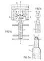
- it is the upper end or pole of the cap 1 ending the neck 2 of the bulb 3 or its lower base 4 which is brought to the melting temperature of the glass.
- the device according to the invention and which implements this method comprises at least one source generating a flame affecting the shape of a very narrow dart and directed so as to shave the area in which the orifice must be realized.
- a stirrup-shaped assembly 9 carrying on its two opposite branches two nozzles or injectors 10 each connected to a not shown source of a gas or of a mixture of combustible gases, the diameter of these nozzles being adjusted so as to produce the two darts 8 whose ends meet to form a halo 11 in the form of a substantially vertical disc and tangent to the surface of the glass to be drilled.
- the halo where the highest temperature prevails which can lead to the melting of the glass, only affects the pole of the cap of the neck of the bulb or its base on a restricted zone, the surrounding zones being subjected only to a lower temperature and consequently escaping from the phenomenon of fusion.
- the orifice can be produced at a point favorable to the vicinity or most as close as possible to the longitudinal axis XX 'of the ampoule to best facilitate the operations for removing its contents.
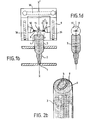
- FIG. 3 Such an apparatus is shown in FIG. 3. It is essentially constituted by a cylindrical part 12 comprising a window 13 in which is capable of sliding, as will be seen below, the stirrup 9 carrying the injectors 10 which has been discussed above. Furthermore, along a generatrix of this cylindrical part, a longitudinal slot 14 is produced carrying a scale of graduations in front of which a cursor 15 can move in the manner which will be described below and whose role will also emerge from this. description.
- the stirrup 9 is carried by a plate 16 made integral with a rack 17 engaged with a gear 18 capable of being rotated by any suitable means, for example an electric motor 19.
- the index or cursor 15 is mounted, via a nut 21, on a shaft 20 whose rotation can be controlled by a crank button 22 to bring said cursor to the desired position opposite the chosen graduation of the graduated scale of the slot 14.
- This position regulates the amplitude of the up-down movement of the stirrup 9, for example by an electrical connection being established by contacts 23a, 23b, 23c provided on the lower part of the rack-holder part and on the index-holder part so as to electrically control the motor 19, and hence the rotation of the gear 18 in engagement with the rack 17.
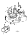
- Such an apparatus can be used as indicated above in a fully automatic assembly illustrated in FIG. 4, allowing a sterility test to be carried out.
- This assembly essentially comprises the bulb opening station 12 as just described, cooperating with a device for presenting the bulbs to be opened.
- the latter can be constituted for example by a bulb holder plate 24 capable of being driven in a step-by-step rotation movement, as will be seen below.
- the height of the bulbs to be opened dictates the height at which the caliper carrying the heat flux must be located so as to implement the method of the invention as defined above.
- the assembly includes a station for sampling the contents of each ampoule, this station being constituted, on the one hand, by a cylindrical element 25 of identical construction and operation to those of the element 12, except for the fact that the caliper carrying the heat flux generator is replaced by a hypodermic needle holder 26-26a capable of being animated by an up-down movement whose amplitude is regulated, as previously , by a cursor brought to a graduated scale 27 by the crank button 28 according to the depth to which the needle must penetrate inside an open bulb.
- the hypodermic needle 26a is directly connected to the sterility checking device. This can be of any known type.
- the electrical devices and circuits for controlling this cycle are of the conventional type and can be produced in any suitable manner known per se.
- the stirrup 9 may include a cooling circuit constituted by a circulation of fluid inside its branches.
- the gas or fuel gas mixture intake circuit has not been shown for the sake of clarity and simplification.
- the invention can be applied to the sterility test of dry products (soluble or lyophilized powders).
- a product solubilization station is provided between the opening station and the sampling station.
Landscapes
- Chemical & Material Sciences (AREA)
- Engineering & Computer Science (AREA)
- Organic Chemistry (AREA)
- Health & Medical Sciences (AREA)
- Life Sciences & Earth Sciences (AREA)
- Materials Engineering (AREA)
- General Health & Medical Sciences (AREA)
- Public Health (AREA)
- Epidemiology (AREA)
- Zoology (AREA)
- Proteomics, Peptides & Aminoacids (AREA)
- Wood Science & Technology (AREA)
- Bioinformatics & Cheminformatics (AREA)
- Analytical Chemistry (AREA)
- Molecular Biology (AREA)
- Immunology (AREA)
- Biotechnology (AREA)
- Biophysics (AREA)
- Biochemistry (AREA)
- Physics & Mathematics (AREA)
- General Engineering & Computer Science (AREA)
- Microbiology (AREA)
- Genetics & Genomics (AREA)
- Mechanical Engineering (AREA)
- Animal Behavior & Ethology (AREA)
- Veterinary Medicine (AREA)
- Medical Preparation Storing Or Oral Administration Devices (AREA)
- Devices For Opening Bottles Or Cans (AREA)
- Re-Forming, After-Treatment, Cutting And Transporting Of Glass Products (AREA)
- Sampling And Sample Adjustment (AREA)
- Devices For Use In Laboratory Experiments (AREA)
Applications Claiming Priority (2)
| Application Number | Priority Date | Filing Date | Title |
|---|---|---|---|
| FR8120734A FR2515511B1 (fr) | 1981-11-05 | 1981-11-05 | Procede pour l'ouverture aseptique et anti-particulaire d'enceintes en verre scelle et dispositif et appareil mettant en oeuvre ce procede |
| FR8120734 | 1981-11-05 |
Publications (2)
| Publication Number | Publication Date |
|---|---|
| EP0079279A1 EP0079279A1 (fr) | 1983-05-18 |
| EP0079279B1 true EP0079279B1 (fr) | 1985-05-22 |
Family
ID=9263719
Family Applications (1)
| Application Number | Title | Priority Date | Filing Date |
|---|---|---|---|
| EP82402029A Expired EP0079279B1 (fr) | 1981-11-05 | 1982-11-04 | Procédé pour l'ouverture aseptique et anti-particulaire d'enceintes en verre scellé et dispositif et appareil mettant en oeuvre ce procédé |
Country Status (5)
| Country | Link |
|---|---|
| US (1) | US4465501A (en:Method) |
| EP (1) | EP0079279B1 (en:Method) |
| JP (1) | JPS5886161A (en:Method) |
| DE (1) | DE3263783D1 (en:Method) |
| FR (1) | FR2515511B1 (en:Method) |
Families Citing this family (10)
| Publication number | Priority date | Publication date | Assignee | Title |
|---|---|---|---|---|
| JPS63242260A (ja) * | 1987-03-31 | 1988-10-07 | エーザイ株式会社 | 薬液収集装置 |
| AT404827B (de) * | 1994-07-28 | 1999-03-25 | Avl Verbrennungskraft Messtech | Verfahren und vorrichtung zur entnahme einer flüssigkeit aus einer verschlossenen glasampulle |
| AT406014B (de) * | 1997-12-22 | 2000-01-25 | Avl List Gmbh | Vorrichtung zur entnahme einer flüssigkeit aus einer glasampulle |
| CN103193379A (zh) * | 2013-04-18 | 2013-07-10 | 柯显信 | 一种避免药用安瓿瓶内表面产生碎屑的方法 |
| CN103496659B (zh) * | 2013-09-29 | 2015-08-19 | 北京大学深圳医院 | 医用药瓶开启装置及开启方法 |
| CN103803466B (zh) * | 2014-02-18 | 2016-03-02 | 董小强 | 一种平推换瓶式的安瓿瓶自动开瓶装置 |
| EP3356238B1 (en) * | 2015-09-30 | 2020-01-08 | Muffin Incorporated | Systems and methods for filling and sealing vials |
| CN109354394B (zh) * | 2018-10-12 | 2021-11-12 | 湖北新华光信息材料有限公司 | 一种石英安瓿瓶熔封装置及方法 |
| CN109502526B (zh) * | 2018-10-18 | 2021-07-06 | 孔祥媛 | 一种医疗安瓿瓶辅助掰断装置 |
| US20220064048A1 (en) * | 2020-08-31 | 2022-03-03 | Seyed Mohammadreza Jafari | Sealing glass ampules using electricity generated plasma arc |
Family Cites Families (12)
| Publication number | Priority date | Publication date | Assignee | Title |
|---|---|---|---|---|
| GB191581A (en) * | 1921-12-12 | 1923-01-18 | George Edgar Bateson | Improvements relating to machines for forming the necks of glass or the like bottles |
| US2224486A (en) * | 1937-09-14 | 1940-12-10 | Kimble Glass Co | Manufacture of glass ampoules |
| GB533473A (en) * | 1938-11-09 | 1941-02-13 | British Thomson Houston Co Ltd | Improvements in and relating to methods of making glass bulbs |
| US2704418A (en) * | 1950-03-03 | 1955-03-22 | Automatic Glassware Machinery | Machine for the manufacture of hollow glass articles |
| US2956372A (en) * | 1957-05-14 | 1960-10-18 | Westinghouse Electric Corp | Tipping-off method |
| US3188191A (en) * | 1959-08-06 | 1965-06-08 | Union Carbide Corp | Method of severing glass tubing |
| GB1084252A (en:Method) * | 1964-02-12 | |||
| US3923487A (en) * | 1971-08-10 | 1975-12-02 | Owens Illinois Inc | Method of making glass ampuls in a non-contaminating manner |
| JPS50143681A (en:Method) * | 1974-05-08 | 1975-11-19 | ||
| US4036698A (en) * | 1974-11-06 | 1977-07-19 | Millipore Corporation | Method and apparatus for membrane filter sterility testing |
| GB1571586A (en) * | 1976-05-04 | 1980-07-16 | Autopack Ltd | Method and apparatus for filling closed ampoules |
| JPS566779A (en) * | 1979-06-29 | 1981-01-23 | Nippon Steel Corp | Pipe working device |
-
1981
- 1981-11-05 FR FR8120734A patent/FR2515511B1/fr not_active Expired
-
1982
- 1982-11-02 US US06/438,666 patent/US4465501A/en not_active Expired - Lifetime
- 1982-11-02 JP JP57193250A patent/JPS5886161A/ja active Granted
- 1982-11-04 DE DE8282402029T patent/DE3263783D1/de not_active Expired
- 1982-11-04 EP EP82402029A patent/EP0079279B1/fr not_active Expired
Also Published As
| Publication number | Publication date |
|---|---|
| JPS5886161A (ja) | 1983-05-23 |
| FR2515511A1 (fr) | 1983-05-06 |
| EP0079279A1 (fr) | 1983-05-18 |
| FR2515511B1 (fr) | 1985-11-15 |
| JPS6366537B2 (en:Method) | 1988-12-21 |
| DE3263783D1 (en) | 1985-06-27 |
| US4465501A (en) | 1984-08-14 |
Similar Documents
| Publication | Publication Date | Title |
|---|---|---|
| EP0079279B1 (fr) | Procédé pour l'ouverture aseptique et anti-particulaire d'enceintes en verre scellé et dispositif et appareil mettant en oeuvre ce procédé | |
| FR2767583A1 (fr) | Dispositif pour le prelevement et/ou l'injection a l'interieur d'un tube d'echantillon bouche | |
| FR2580078A1 (en:Method) | ||
| EP1370361A2 (fr) | Tete de lavage et d'extraction pour appareil de lavage de microplaques et appareil correspondant | |
| WO2011051192A1 (fr) | Dispositif et procede de recuperation de particules magnetiques piegees sur un bouchon magnetique | |
| EP0316698B1 (fr) | Dispositif pour délivrer une dose prédéterminée d'un liquide | |
| FR2905592A1 (fr) | "machine pour remplir de semence des paillettes d'insemination artificielle" | |
| FR2597260A1 (fr) | Procede d'introduction directe automatique d'echantillons dans un spectrometre de masse, et dispositif pour la mise en oeuvre de ce procede | |
| EP4234509A2 (fr) | Procede et installation de desalcalinisation de recipients en verre par voie liquide | |
| EP0006556B1 (fr) | Procédé et dispositif pour déposer dans un récipient une dose prédéterminée d'une substance liquide | |
| EP0522959B1 (fr) | Procédé et installation pour transférer en dehors d'une enceinte étanche un fluide contenu dans un récipient fermé | |
| FR2691648A1 (fr) | Procédé et appareil pour la réduction de volume de contenants en matière plastique. | |
| EP2683647B1 (fr) | Station de desoperculage selectif de cartes gel | |
| EP1861331B1 (fr) | Sertisseuse a verin electrique | |
| FR3057665A1 (fr) | Appareil pour la coloration automatique d'echantillons sur lames de microscope | |
| FR2606006A1 (fr) | Dispositif d'alimentation en bouchons d'un ensemble de tetes de bouchage de recipients | |
| FR2460885A1 (fr) | Procede de thermoscellage et dispositifs de mise en oeuvre | |
| FR2725274A1 (fr) | Procede de detection pour le reperage de debris de verre a l'interieur de bouteilles | |
| CH693090A5 (fr) | Procédé et appareil pour ramollir et écraser les bouteilles en matériau thermoplastique. | |
| FR2574563A1 (fr) | Procede de denudage de fibres optiques et dispositif de mise en oeuvre de ce procede | |
| JP2000118595A (ja) | アンプル瓶の熔閉装置及び方法 | |
| FR2763561A1 (fr) | Systeme de gonflage sterile pour un sac a paroi souple ferme | |
| EP3271075B1 (fr) | Dispositif de preparation d'une couche de cellules biologiques sur une lame et appareil de preparation automatique d'une couche de cellules utilisant ledit dispositif | |
| BE885842Q (fr) | Tete capsuleuse pour bouteilles ou analogues | |
| WO2014091108A1 (fr) | Procédé de découpe à froid d'une lampe |
Legal Events
| Date | Code | Title | Description |
|---|---|---|---|
| PUAI | Public reference made under article 153(3) epc to a published international application that has entered the european phase |
Free format text: ORIGINAL CODE: 0009012 |
|
| AK | Designated contracting states |
Designated state(s): BE CH DE GB IT LI NL |
|
| 17P | Request for examination filed |
Effective date: 19830624 |
|
| ITF | It: translation for a ep patent filed | ||
| GRAA | (expected) grant |
Free format text: ORIGINAL CODE: 0009210 |
|
| AK | Designated contracting states |
Designated state(s): BE CH DE GB IT LI NL |
|
| REF | Corresponds to: |
Ref document number: 3263783 Country of ref document: DE Date of ref document: 19850627 |
|
| PLBE | No opposition filed within time limit |
Free format text: ORIGINAL CODE: 0009261 |
|
| STAA | Information on the status of an ep patent application or granted ep patent |
Free format text: STATUS: NO OPPOSITION FILED WITHIN TIME LIMIT |
|
| 26N | No opposition filed | ||
| ITTA | It: last paid annual fee | ||
| PGFP | Annual fee paid to national office [announced via postgrant information from national office to epo] |
Ref country code: NL Payment date: 20011016 Year of fee payment: 20 |
|
| PGFP | Annual fee paid to national office [announced via postgrant information from national office to epo] |
Ref country code: GB Payment date: 20011029 Year of fee payment: 20 |
|
| PGFP | Annual fee paid to national office [announced via postgrant information from national office to epo] |
Ref country code: CH Payment date: 20011128 Year of fee payment: 20 |
|
| PGFP | Annual fee paid to national office [announced via postgrant information from national office to epo] |
Ref country code: BE Payment date: 20011129 Year of fee payment: 20 |
|
| PGFP | Annual fee paid to national office [announced via postgrant information from national office to epo] |
Ref country code: DE Payment date: 20011214 Year of fee payment: 20 |
|
| REG | Reference to a national code |
Ref country code: GB Ref legal event code: IF02 |
|
| REG | Reference to a national code |
Ref country code: CH Ref legal event code: PUE Owner name: MILLIPORE S.A. TRANSFER- MILLIPORE Ref country code: CH Ref legal event code: NV Representative=s name: FUHRER MARBACH & PARTNER |
|
| NLS | Nl: assignments of ep-patents |
Owner name: MILLIPORE |
|
| PG25 | Lapsed in a contracting state [announced via postgrant information from national office to epo] |
Ref country code: LI Free format text: LAPSE BECAUSE OF EXPIRATION OF PROTECTION Effective date: 20021103 Ref country code: GB Free format text: LAPSE BECAUSE OF EXPIRATION OF PROTECTION Effective date: 20021103 Ref country code: CH Free format text: LAPSE BECAUSE OF EXPIRATION OF PROTECTION Effective date: 20021103 |
|
| PG25 | Lapsed in a contracting state [announced via postgrant information from national office to epo] |
Ref country code: NL Free format text: LAPSE BECAUSE OF EXPIRATION OF PROTECTION Effective date: 20021104 |
|
| REG | Reference to a national code |
Ref country code: GB Ref legal event code: PE20 Effective date: 20021103 |
|
| REG | Reference to a national code |
Ref country code: CH Ref legal event code: PL |
|
| NLV7 | Nl: ceased due to reaching the maximum lifetime of a patent |
Effective date: 20021104 |