EP0079079A1 - Apparat und Detektorkopf für radioaktive Aerosolteilchen - Google Patents
Apparat und Detektorkopf für radioaktive Aerosolteilchen Download PDFInfo
- Publication number
- EP0079079A1 EP0079079A1 EP82110312A EP82110312A EP0079079A1 EP 0079079 A1 EP0079079 A1 EP 0079079A1 EP 82110312 A EP82110312 A EP 82110312A EP 82110312 A EP82110312 A EP 82110312A EP 0079079 A1 EP0079079 A1 EP 0079079A1
- Authority
- EP
- European Patent Office
- Prior art keywords
- filter
- support
- detection head
- block
- detection device
- Prior art date
- Legal status (The legal status is an assumption and is not a legal conclusion. Google has not performed a legal analysis and makes no representation as to the accuracy of the status listed.)
- Ceased
Links
Images
Classifications
-
- G—PHYSICS
- G01—MEASURING; TESTING
- G01T—MEASUREMENT OF NUCLEAR OR X-RADIATION
- G01T7/00—Details of radiation-measuring instruments
- G01T7/02—Collecting means for receiving or storing samples to be investigated and possibly directly transporting the samples to the measuring arrangement; particularly for investigating radioactive fluids
- G01T7/04—Collecting means for receiving or storing samples to be investigated and possibly directly transporting the samples to the measuring arrangement; particularly for investigating radioactive fluids by filtration
Definitions
- the present invention relates in particular to a device,. an assembly and a head for detecting particles of an aerosol having radioactive properties, which can be used in particular to determine whether or not there is atmospheric contamination by radioactive aerosols, in particular on building sites or in premises located nearby or in nuclear power plants.
- the object of the present invention is to remedy the drawbacks of existing detection apparatuses and to design an easy-to-decontaminate detection device and assembly, of simple construction, capable of operating continuously for a relatively long period of time and, in a variant, portable.
- the device for detecting particles of an aerosol exhibiting radioactive properties comprises a flow channel for the aerosol gas, a particle retention filter arranged across the flow channel and at the through which the gas passes, this flow channel comprising, upstream of said filter, a distribution chamber containing in its wall opposite to said filter a detection head the active face of which faces away from said filter and comprising at least one inlet for the gas and, downstream of the filter, a distribution chamber connected to a suction pump.
- the detection device is such that said filter is in the form of a ribbon, that means are provided for advancing said filter step by step in the direction of its length from the active side of said detection head, that a support surrounds said flow channel and faces said filter on the side of said distribution chamber and that a presser means is provided for applying or pressing said filter against said support so that the flow channel is sealed.
- the detection device preferably comprises a block which delimits said vacuum chamber and which is slidably mounted to approach or move away from said support, said block comprising a counter-support which surrounds said flow channel and faces said support on the other side of said filter and that drive means are provided for moving said block in the direction which brings it closer to said support so that said counter-support applies or presses said filter against said support and in the direction which moves it away from said support so as to release said filter for advancement, said block and said drive means forming said presser means.
- said drive means are preferably formed by a screw-nut system whose screw or nut is integral with said block and whose nut or screw can be driven by an electric motor in one way or the other to move said block away from said support.
- said drive means comprise at least one spring which acts on said block in the direction which brings it closer to said support and at least one electromagnet whose movable part is connected to said block, this electromagnet acting against said spring in order to move said block away from said support.
- This alternative embodiment makes it possible to have a clamping force of the filter between the block and the constant support since it is exerted by said spring and, moreover, the time necessary for the advancement of the filter is brief because the movement of removal of the block is caused by the electromagnet.
- the vacuum chamber delimited by said block is preferably connected to said suction pump by a flexible pipe or a bellows.
- the detection device preferably comprises two supports adapted to receive said ribbon filter in the form of rolls, one carrying the filter roll in supplying ribbon and the other receiving the used filter, the filter in ribbon extending from one support to the other passing between said support and said presser means and said support receiving the used filter being capable of being driven in rotation by an electric motor so as to advance step by step -not in the direction of its length, said ribbon filter in front of said detection head.
- the detection device may also comprise two guide rollers for said ribbon filter, the ribbon filter extending from one roller to the other passing between said support and said presser means. These two guide rollers can be placed between said supports.
- the detection device preferably comprises an open lateral slit or an open lateral free space allowing insertion of said strip filter between said support and said presser means at any point of its length by sliding it laterally. In this way, the installation of the ribbon filter in front of the detection head is very simple.
- the detection device may comprise a lead shield surrounding said flow channel and said detection head.
- the detection device preferably comprises a thin plastic sheet removably mounted for its change in front of the active face of said detection head so as to protect the latter.
- the present invention also relates to a set 'for detecting particles of an aerosol having radioactive properties, this set being in the form of a suitcase portable easily by a person and comprising, inside, the detection device which has just been described.
- the detection assembly comprises a portable suitcase comprising at least two compartments separated by a partition and an access cover per compartment, the detection device defined above being mounted in one of the compartments while the electronic control and measurement circuits therein associated are mounted in the other, light and / or sound signaling means connected to the electronic circuit being mounted on said suitcase and the light signaling means being visible from the outside of this suitcase.
- the detection device and the electronic circuits are preferably mounted on said partition.
- the present invention also relates to a particular detection head intended to be mounted in the detection device defined above, this detection head being adapted in particular for the measurement of surface activity ⁇ on the surface formed by said filter, in an environment ⁇ .
- detection head preferably not requiring shielding while retaining high performance, to maximize the detector surface-to-volume ratio of the detection head and to obtain as low a background noise as possible.
- a detection head successively comprising a first plane semiconductor detector facing said surface, a screen absorbing ⁇ radiation from said surface and a second planar semiconductor detector, said detectors and said screen being stacked so as to form a unit, the detectors having substantially the same thickness, said first detector serving for measuring ⁇ activity and being sensitive to 0 radiation and said second detector serving for measuring ⁇ radiation for the correction of the measurement made by the first detector. It is also preferable that said detectors have the same surface.
- a screen such that electrons do not reach the second detector while limiting the distance separating said detectors so that the response in an external flux ⁇ is substantially identical or in a constant ratio whatever or the distribution of this flow.
- said detectors can be directly attached to the screen.
- a detection head such that said detectors and said screen are mounted in a housing having an opening on the side of said surface.
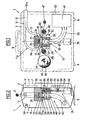
- the portable detection assembly represented in FIGS. J and 2 generally identified by the reference 1 comprises a suitcase generally identified by the reference 2.
- the suitcase 2 comprises two compartments 3 and 4 which are separated by a vertical partition 5.
- the compartments 3 and 4 are delimited by covers in the form of a bowl 6 and 7 which can be dismantled, the means of connection between the covers 6 and 7 and the peripheral edge of the partition 5 not having been shown since they are conventional.
- the suitcase 2, when the covers 6 and 7 are mounted, is sealed to avoid any infiltration inside the suitcase of dust or liquid products.
- the suitcase 2 comprises two feet 8 making it possible to place the suitcase and to keep it vertical and comprises at its upper part a manual gripping handle 9 provided for its transport.
- the detection device 10 comprises a gas supply pipe generally identified by the reference 11 and comprising an inlet conduit 12 extending longitudinally to the Suitcase 2 and having an open end J2a extending slightly to the outside of the suitcase 2.
- the other end of the conduit 12 is divided into two conduits 13 and 14 which meet so as to form a loop 11a.
- the loop 11a formed by the conduits 13 and 14 is in a vertical plane parallel to the partition 5 and extends downwards.
- the conduits 13 and 14 are, in the example shown, of rectangular section. To prevent the end 12a from being accidentally blocked, it could for example be surrounded at a distance by a large mesh grid which does not stop the dust and preferably does not disturb the flow of air.
- the lower part of the loop 11a comprises two substantially parallel parallel opposite walls 15 and 16.
- an opening 17 and in the lower wall 16 is formed an opening 18, the openings 17 and 18 being one in opposite each other and cylindrical.
- a cylindrical detection head 19 In the opening 17 of the upper wall 15 is disposed a cylindrical detection head 19 whose axis is vertical and whose active face which faces the opening 18 is substantially at the level of the upper wall 15.
- a sheet 20 made of plastic is mounted just in front of the contact face of the detection head 19 so as to be substantially at the level of the internal face of the wall 15.
- the lower part of the loop formed by the conduits 13 and 14 and the detection head 19 are ⁇ surrounded by a support block 21 which, in the example shown, is in the form of a parallelepiped whose horizontal lower face 22 is at the level of the external face of the wall 16.
- the block 21 is fixed to the partition 5 of the suitcase 2 by any known means and for example by screws not shown,
- a sealed connection which can be effected by any known means.
- the plastic sheet 20 can be fixed to a ring which can be screwed into the opening 17, the detection head being for example mounted in a recess of the block 21 by a screw.
- a distribution chamber 23 into which the gas from the end 12a of the inlet duct 12 penetrates by two lateral sides to flow through the opening 18 of the bottom wall 16 .
- a block 24 which, in the example shown, is of substantially parallelepipedic and comprises a substantially horizontal upper face 26, is mounted sliding in the vertical direction on the partition 5.
- the block 24 comprises two lateral shoulders 27 and 28 which are held by vertical slides 29 and 30 fixed on the partition 5 for example by screws.
- a drive means In order to move the block 24 up or down, there is provided a drive means generally identified by the reference 31.
- the drive means 31 comprises a vertical axis 32, the upper part 33 of which is threaded and enters a tapped hole 34 of the block 24.
- the lower end of the axis 32 is connected to an electric motor or to a gear motor 35 which is fixed to the partition 5.
- the axis 32 comprises a shoulder 36 which is caught between the two fingers of a fork 37 fixed to the plate 5. This fork 37, in cooperating with the shoulder 36, keeps the axis 32 in translation.
- the motor 35 will rotate in one direction or the other, it will drive, via the axis 32, the block 24 in translation up or down.
- the block 24 includes a substantially cylindrical vertical passage defining a vacuum chamber 38 whose upper opening 39 is opposite the opening 18 of the lower wall 16 of the pipe 11 and substantially of the same diameter and whose lower opening 40 is, via a pipe 42, connected to a suction pump 41 fixed to the partition 5, this pipe being flexible so as not to interfere with the translational movement of the block 24.
- the ends of the flexible pipe 42 are conventionally fixed, one to the block 24 and the other to the inlet pipe of the suction pump 41.
- the suction pump 41 comprises an outlet pipe 43 which extends longitudinally to the case 2 and which leads out of it.
- the outlet duct 43 opens on the same side as the open end 12a of the supply duct 12.
- the duct 43 is preferably placed on the side opposite entry J2a or on one of the lateral sides of suitcase 2.
- a ribbon filter 44 wound in the form of a roller 45 disposed on a support such as an axis 46 mounted on the partition 5, extends between the outer face of the wall 16 of the supply pipe 11 and the upper face 26 of the block 24 and is wound around a second support such as an axis 47 which is also mounted on the partition 5 - So that the ribbon filter 44 extends substantially horizontally between the external face of the wall 16 and the upper face 26 of the block 24, there are two lateral rollers 48 and 49 mounted rotating on the partition 5 and comprising a flat-bottomed groove against which the ribbon filter 44 is supported.
- the filter 44 may deform and penetrate into the opening 39 of the block away from the detection head. This deformation may distort the measurement.
- the support axis 47 can be rotated by an electric motor 50 fixed to the partition 5 in the compartment 4.
- the ribbon filter 44 extends between the opening 18 of the chamber 23 and the opening 39 of the chamber 38 and has a width greater than the diameter of these openings to overflow on each side.
- the block 24 In a position shown in FIGS. 1 and 2, the block 24 is in its lower position and is therefore distant from the lower wall 16 of the supply pipe 11.
- the motor 35 In order to create a completely sealed gas flow channel from the inlet 12a of the supply pipe 1] to the suction pump 41, it suffices to actuate the motor 35 to move the block 24 upwards so that its upper face 26 comes to apply or press sealingly the ribbon filter 44 against the outer face of the wall 16 surrounding the opening 18.
- the outer face of the wall 16 of the pipe 11 forms a support for the filter 44
- the shoulder 51 forms a counter -support for the filter 44
- the movable block 24 forms a medium presser pe stating to return seals the flow channel at the filter.
- the block 24 presses the ribbon filter 44 against the outer face of the wall 16 corresponds to the position in which the measurement of atmospheric contamination can be carried out.
- the pump 41 by actuating the pump 41, the atmospheric air charged with particles or dust is sucked in, the air penetrating into the sealed channel formed by the tubing 11, the chamber 38 and the flexible pipe through the end 32a of the tubing.
- the ribbon filter must be advanced by one step to place a new part in front of the detection head.
- the motor 35 is actuated to lower the block 24 and, thanks to the motor 50, the ribbon filter 44 is pulled to make it advance one step.
- the block 24 is then raised using the motor 35 to again create the necessary sealing of the flow channel to carry out a new measurement period.
- the block when the block is in its position away from the outer face of the wall 16 of the chamber 23, there is an open slot or a free space 51a opening laterally which allows a access between the support formed by the external face of the wall 16 of the pipe 11 and the counter-support formed by the seal 51.
- the slot 51a is useful for changing the filter roll into a ribbon when it is completely used . Indeed, it allows to easily dispose the end part of a new ribbon filter by sliding it laterally through the slot 5Ja to arrange the new filter in front of the detection head, the new ribbon filter roll then being mounted on the axis 46 and the free end of the ribbon filter being attached to the motor axis 47 by any known means.
- blocks 21 and 24 are made of lead and a core 52 is disposed in the vacuum chamber 38, this core 52 being held in block 24 by means of radial lugs 53, the block 24 being, for the purpose of mounting the core 52, in two parts. It can be noted that in certain applications where the shielding is not necessary, the blocks 21 and 24 and the core 52 may be made of another material such as a plastic material.
- compartment 4 of the suitcase 2 are arranged the electronic control and measurement circuits which are represented in the figure by two plates 54 and 55 which are fixed to the partition 5.
- On the cover 6 are mounted means for signaling such as bulbs 56, these bulbs 56 being visible from the outside.
- These signaling means can also include audible alarms.
- One can also provide, in the suitcase 2 a location for the reception of an electrical power source such as a battery.
- the detection head 19, the motor 35, the motor 50, the suction pump 41 and the bulbs 56 are connected, for example by wires not shown, to the electronic circuits 54 and 55 and that it an external electric current supply wire can be provided.
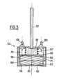
- the detection head shown in FIG. 3 and generally identified by the reference 57 is suitable for measuring the surface activity ⁇ on the surface formed by the filter 44 which is located opposite the detection head in a ⁇ atmosphere.
- the detection head 57 comprises a housing formed by a cylindrical casing 58 provided at one of its ends with an internal shoulder 59 defining an opening 60 and a cover 61 forming the other end of the casing 58.
- the detection head 57 successively comprises a first semiconductor detector 62 in the form of a disc, a screen or absorbent 63 in the form of a cylinder, which in the example shown is in two parts separated by a radial insulating film 64 whose faces are metallized but which could be in one piece, a second detector to semiconductor 65 also being in the form of a disk with the same surface area as the detector 62, a solid washer 66 and a spring 67 placed between the washer 66 and the cover 61.
- the detection head 57 is designed so that its detection components are stacked in a box to form a unit of small volume.
- connection 68 and 69 On the cover 61 are provided two external connection connections 68 and 69, the connection 68 being electrically connected to the detector 65 by a wire 70 and the connection 69 being electrically connected to the lower metallized face of the insulation 64 by a wire 71 which extends in an axial groove of the casing 58 so as to bypass the solid washer 66 and the screen 63.
- the upper metallized face of the insulation 64 is electrically connected to the mass of the casing 58.
- the ' external branch connections 68 and 69 can be connected to electronic circuits 54 and 55 by electrical wires such as shielded cables.
- the detection head 57 further comprises an axial threaded rod 72 fixed to the cover 61, this threaded rod 72 being provided for fixing the detection head 57 to the block 21 of the detection device 10 shown in FIGS. 1 and 2.
- the detectors 62 and 65 are designed such that the detector 62 is used for measuring the activity ⁇ while being sensitive to radiation 0 and that the detector 65 measures the radiation ⁇ with a view to correcting the measurement carried out by the detector 62, the screen 63 which may for example be made of aluminum used to absorb ⁇ radiation.
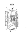
- a detection assembly 1a which corresponds to the detection assembly 1 shown in FIGS. 1 and 2 and which differs from it only in that it comprises, a means of drive of the different block 24.
- the motor drive means 31 of the detection assembly 1 is replaced by a drive means 31a with an electromagnet.
- the drive means 31a provided in this variant in fact comprises an electromagnet 73 whose outer casing is fixed to the partition 5 by means of a console 74.
- the movable rod 75 of the electromagnet 73 is parallel to the slides 27 and 28 and extends or is extended upwards to the block 24a, l 'upper end of the rod 75 being fixed to the block 24a.
- the upper end 76 of the rod 75 is screwed into the block 24a.
- the drive means 3Ja also comprises a spring 77 which acts on the block 24a in the direction which brings it closer to the block 21.
- the spring 77 is placed around the rod 75 and is supported on the one hand on the upper edge of the casing of the electromagnet 73 and on the other hand against a shoulder 78 carried by the rod 75.
- the spring 77 is placed below the block it must be powerful enough to carry the block 24a and the elements carried by the latter and to exert the clamping force of the filter 44 between the shoulder 51 and the wall 20 surrounding the opening 18.
- the electromagnet 73 When it is desired to release the filter 44, the electromagnet 73 is actuated which pulls the block 24a downwards by compressing the spring 77. When the filter is advanced, the electromagnet 73 is released and then the spring 77 raises the block 24a and applies the filter 44 against the wall 20 surrounding the opening. It can be noted that the clamping force of the filter 44 will be the same each time because the spring 77 returns to its initial position.
- this drive means 31a is faster than the drive means 3J provided previously. Consequently, the time required to change the position of the filter 44 should advantageously be shortened.
- the detection assembly as just described and as shown in the figures and 2 has many advantages. Indeed, it can be very light and as it is in the form of a suitcase, it can be easily transported manually and placed at the exact place where one wishes to measure possible atmospheric contamination. In addition, it includes signaling means which immediately alert the personnel and it can have a very long operating autonomy. Indeed, thanks to the fact that the filter is in the form of a ribbon and that means are provided for advancing the filter 44 and means for creating the airtightness of the air flow anal, it is possible to carry out a very rapid change of the useful filter part and therefore to have a practically continuous monitoring of the contamination.
- the electronic circuits 54, 55 must be able to operate the detection assembly 1 automatically and in particular to control the suction pump 41, the motors 35 and 50, carry out the detection measurements using of the detection head 19, to interpret these measurements to control the signaling means 56 and to report all the operating faults and in particular the lack of filter.
- the case 2 includes two separate compartments 3 and 4 so that access to each compartment can be selected. Indeed, access to compartment 3 in particular for changing the filter 44 can be authorized to low-qualified personnel while access to compartment 4 in which the electronic circuits are arranged can be authorized to more qualified personnel. For this purpose, different locks can be mounted on the covers 6 and 7 of the compartments 3 and 4.
- the present invention is obviously not limited to the example described above.
- a detection device having a fixed block 24 on which could be mounted a presser means disposed in the flow channel and capable of forming a seal at the location of the ribbon filter, can design a suitcase of a completely different shape and we can make a detection head mounted in a different way while keeping the detectors and the screen stacked.
Landscapes
- Chemical & Material Sciences (AREA)
- Analytical Chemistry (AREA)
- Physics & Mathematics (AREA)
- Health & Medical Sciences (AREA)
- Life Sciences & Earth Sciences (AREA)
- General Physics & Mathematics (AREA)
- High Energy & Nuclear Physics (AREA)
- Molecular Biology (AREA)
- Spectroscopy & Molecular Physics (AREA)
- Measurement Of Radiation (AREA)
Applications Claiming Priority (2)
| Application Number | Priority Date | Filing Date | Title |
|---|---|---|---|
| FR8121086A FR2516243A1 (fr) | 1981-11-10 | 1981-11-10 | Dispositif, ensemble et tete de detection des particules d'un aerosol presentant des proprietes radioactives |
| FR8121086 | 1981-11-10 |
Publications (1)
| Publication Number | Publication Date |
|---|---|
| EP0079079A1 true EP0079079A1 (de) | 1983-05-18 |
Family
ID=9263881
Family Applications (1)
| Application Number | Title | Priority Date | Filing Date |
|---|---|---|---|
| EP82110312A Ceased EP0079079A1 (de) | 1981-11-10 | 1982-11-09 | Apparat und Detektorkopf für radioaktive Aerosolteilchen |
Country Status (2)
| Country | Link |
|---|---|
| EP (1) | EP0079079A1 (de) |
| FR (1) | FR2516243A1 (de) |
Cited By (11)
| Publication number | Priority date | Publication date | Assignee | Title |
|---|---|---|---|---|
| FR2547421A1 (fr) * | 1983-06-10 | 1984-12-14 | Commissariat Energie Atomique | Procede de detection de la contamination atmospherique par des aerosols de particules alpha et detecteur portatif de cette contamination mettant en oeuvre le procede |
| US5489775A (en) * | 1993-04-16 | 1996-02-06 | Commissariat A L'energie Atomique | Method and device for the energy-calibration of an electronic unit for detecting beta and/or X photons and gamma radiations with compton distribution emited by a radioactive aerosol |
| US5932879A (en) * | 1996-05-07 | 1999-08-03 | Regents Of The University Of Michigan | Solid state beta-sensitive surgical probe |
| US6076009A (en) * | 1997-05-05 | 2000-06-13 | The University Of Michigan | Solid state beta-sensitive surgical probe |
| WO2013135938A1 (es) * | 2012-03-16 | 2013-09-19 | Universitat Rovira I Virgili | Estación de identificación y medida en tiempo real de la radiactividad ambiental gamma mediante espectrometría sobre filtro de papel |
| WO2014191411A1 (fr) * | 2013-05-28 | 2014-12-04 | Tech Systemes | Systeme de prelevement et utilisation de ce systeme |
| CN104216002A (zh) * | 2014-09-03 | 2014-12-17 | 北京市射线应用研究中心 | 一种α、β、γ放射性气溶胶连续取样测量装置 |
| US9915600B2 (en) | 2016-02-19 | 2018-03-13 | Research Triangle Institute | Devices, systems and methods for detecting particles |
| US10345216B2 (en) | 2014-08-20 | 2019-07-09 | Research Triangle Institute | Systems, devices, and methods for flow control and sample monitoring control |
| CN111830551A (zh) * | 2020-05-25 | 2020-10-27 | 浙江恒达仪器仪表股份有限公司 | 一种便携式放射性气溶胶自动采样分析装置及检测方法 |
| US11047787B2 (en) | 2019-04-29 | 2021-06-29 | Research Triangle Institute | And method for optical bench for detecting particles |
Families Citing this family (1)
| Publication number | Priority date | Publication date | Assignee | Title |
|---|---|---|---|---|
| FR3069925B1 (fr) | 2017-08-01 | 2023-12-08 | Bertin Technologies Sa | Dispositif de collecte et de detection d'aerosols |
Citations (5)
| Publication number | Priority date | Publication date | Assignee | Title |
|---|---|---|---|---|
| GB838144A (en) * | 1958-10-15 | 1960-06-22 | Barcross Ltd | Radioactivity warning apparatus |
| FR1264743A (fr) * | 1960-07-19 | 1961-06-23 | Controls For Radiation | Perfectionnements apportés aux dispositifs pour la détection des rayonnements |
| US3448269A (en) * | 1965-06-28 | 1969-06-03 | Commissariat Energie Atomique | Method and apparatus for analysing radioactive aerosols |
| US4140912A (en) * | 1977-07-25 | 1979-02-20 | The United States Of America As Represented By The Secretary Of The Navy | Atmospheric radon monitor |
| FR2456331A1 (fr) * | 1979-05-11 | 1980-12-05 | Commissariat Energie Atomique | Dispositif de prelevement et de controle d'aerosols radioactifs |
-
1981
- 1981-11-10 FR FR8121086A patent/FR2516243A1/fr active Granted
-
1982
- 1982-11-09 EP EP82110312A patent/EP0079079A1/de not_active Ceased
Patent Citations (5)
| Publication number | Priority date | Publication date | Assignee | Title |
|---|---|---|---|---|
| GB838144A (en) * | 1958-10-15 | 1960-06-22 | Barcross Ltd | Radioactivity warning apparatus |
| FR1264743A (fr) * | 1960-07-19 | 1961-06-23 | Controls For Radiation | Perfectionnements apportés aux dispositifs pour la détection des rayonnements |
| US3448269A (en) * | 1965-06-28 | 1969-06-03 | Commissariat Energie Atomique | Method and apparatus for analysing radioactive aerosols |
| US4140912A (en) * | 1977-07-25 | 1979-02-20 | The United States Of America As Represented By The Secretary Of The Navy | Atmospheric radon monitor |
| FR2456331A1 (fr) * | 1979-05-11 | 1980-12-05 | Commissariat Energie Atomique | Dispositif de prelevement et de controle d'aerosols radioactifs |
Cited By (16)
| Publication number | Priority date | Publication date | Assignee | Title |
|---|---|---|---|---|
| FR2547421A1 (fr) * | 1983-06-10 | 1984-12-14 | Commissariat Energie Atomique | Procede de detection de la contamination atmospherique par des aerosols de particules alpha et detecteur portatif de cette contamination mettant en oeuvre le procede |
| EP0128827A1 (de) * | 1983-06-10 | 1984-12-19 | Commissariat A L'energie Atomique | Methode und Verfahren zur Detektion der Luftverschmutzung durch alpha-Aerosole sowie zugehöriger tragbarer Strahlungsdetektor |
| US4607165A (en) * | 1983-06-10 | 1986-08-19 | Commissariat A L'energie Atomique | Process and apparatus for detecting atmospheric contamination by alpha particle aerosols |
| US5489775A (en) * | 1993-04-16 | 1996-02-06 | Commissariat A L'energie Atomique | Method and device for the energy-calibration of an electronic unit for detecting beta and/or X photons and gamma radiations with compton distribution emited by a radioactive aerosol |
| US5932879A (en) * | 1996-05-07 | 1999-08-03 | Regents Of The University Of Michigan | Solid state beta-sensitive surgical probe |
| US6076009A (en) * | 1997-05-05 | 2000-06-13 | The University Of Michigan | Solid state beta-sensitive surgical probe |
| WO2013135938A1 (es) * | 2012-03-16 | 2013-09-19 | Universitat Rovira I Virgili | Estación de identificación y medida en tiempo real de la radiactividad ambiental gamma mediante espectrometría sobre filtro de papel |
| FR3006446A1 (fr) * | 2013-05-28 | 2014-12-05 | Tech Systemes | Systeme de prelevement et utilisation de ce systeme |
| WO2014191411A1 (fr) * | 2013-05-28 | 2014-12-04 | Tech Systemes | Systeme de prelevement et utilisation de ce systeme |
| US10018551B2 (en) | 2014-08-20 | 2018-07-10 | Research Triangle Institute | Devices, systems and methods for detecting particles |
| US10345216B2 (en) | 2014-08-20 | 2019-07-09 | Research Triangle Institute | Systems, devices, and methods for flow control and sample monitoring control |
| US10481070B2 (en) | 2014-08-20 | 2019-11-19 | Research Triangle Institute | Systems, devices, and methods for flow control and sample monitoring control |
| CN104216002A (zh) * | 2014-09-03 | 2014-12-17 | 北京市射线应用研究中心 | 一种α、β、γ放射性气溶胶连续取样测量装置 |
| US9915600B2 (en) | 2016-02-19 | 2018-03-13 | Research Triangle Institute | Devices, systems and methods for detecting particles |
| US11047787B2 (en) | 2019-04-29 | 2021-06-29 | Research Triangle Institute | And method for optical bench for detecting particles |
| CN111830551A (zh) * | 2020-05-25 | 2020-10-27 | 浙江恒达仪器仪表股份有限公司 | 一种便携式放射性气溶胶自动采样分析装置及检测方法 |
Also Published As
| Publication number | Publication date |
|---|---|
| FR2516243B1 (de) | 1984-12-28 |
| FR2516243A1 (fr) | 1983-05-13 |
Similar Documents
| Publication | Publication Date | Title |
|---|---|---|
| EP0079079A1 (de) | Apparat und Detektorkopf für radioaktive Aerosolteilchen | |
| BE1008563A3 (fr) | Dispositif de controle. | |
| FR2684232A1 (fr) | Disjoncteur a vide muni de moyens d'autodiagnostic. | |
| EP0162751A1 (de) | Vorrichtung zur Überwachung der Luftverunreinigung durch Aerosol-Alphateilchen | |
| EP0673098B1 (de) | Regelungs und Bedienungsvorrichtung für ein gekapseltes Versorgungskabel | |
| FR2732775A1 (fr) | Detecteur d'echantillons en continu avec standard | |
| EP2158602B1 (de) | Transport-pod-schnittstelle | |
| CH347903A (fr) | Appareil détecteur de la radioactivité alpha d'un gaz | |
| EP0537074B1 (de) | Leistungsschalter mit Umhüllung aus zusammengesetztem Material, welcher mit einer Überwachungsvorrichtung ausgerüstet ist | |
| WO2009074740A2 (fr) | Dispositif et procede de controle de la contamination radioactive d'un utilisateur | |
| EP3662248B1 (de) | Vorrichtung zum sammeln und entnehmen von aerosolen | |
| EP0326479B1 (de) | Röntgenstrahlungsdetektor für Tomographie | |
| EP3255406A1 (de) | Vorrichtung zur entnahme und analyse einer gasförmigen probe | |
| FR2548789A1 (fr) | Installation pour detecter la presence d'isotopes de l'iode | |
| EP0509919A1 (de) | Automatische Anlage zum Fördern und Wiegen von mit einer radioaktiven Flüssigkeit gefüllten Flaschen zwischen einer Entnahmevorrichtung und einer Analysevorrichtung | |
| FR3006446A1 (fr) | Systeme de prelevement et utilisation de ce systeme | |
| FR2754062A1 (fr) | Dispositif pour analyser une matiere pulverulente circulant dans un conduit | |
| FR2466781A1 (fr) | Dispositif pour la mesure des particules radioactives (isotopes) presentes dans des gaz | |
| Gouyen et al. | An apparatus for analyzing radioactive samples | |
| FR2636584A1 (fr) | Dispositif de transport par pneumatisme pour charges lourdes et volumineuses et de flexibilite accrue | |
| KR100417374B1 (ko) | 간극형 하전입자 검출기의 검출모듈 제조장치 및 제조방법 | |
| FR2505506A1 (fr) | Appareil pour mesurer la concentration de radio-activite de gaz | |
| EP0545780A1 (de) | Messgerät für Alpha-Aktivität einer Lösung | |
| FR2539520A1 (fr) | Appareil pour l'exposition en continu, par contact, de materiaux photosensibles au moyen d'une source lumineuse a fente | |
| CH346046A (fr) | Appareil pour l'analyse spectrale |
Legal Events
| Date | Code | Title | Description |
|---|---|---|---|
| PUAI | Public reference made under article 153(3) epc to a published international application that has entered the european phase |
Free format text: ORIGINAL CODE: 0009012 |
|
| AK | Designated contracting states |
Designated state(s): DE GB |
|
| 17P | Request for examination filed |
Effective date: 19831031 |
|
| STAA | Information on the status of an ep patent application or granted ep patent |
Free format text: STATUS: THE APPLICATION HAS BEEN REFUSED |
|
| 18R | Application refused |
Effective date: 19860227 |
|
| RIN1 | Information on inventor provided before grant (corrected) |
Inventor name: LUCAS, JEAN-JACQUES Inventor name: LAFONT, GUY MARC |