EP0079032B1 - Apparatus for electroplating a metallic workpiece - Google Patents
Apparatus for electroplating a metallic workpiece Download PDFInfo
- Publication number
- EP0079032B1 EP0079032B1 EP82110104A EP82110104A EP0079032B1 EP 0079032 B1 EP0079032 B1 EP 0079032B1 EP 82110104 A EP82110104 A EP 82110104A EP 82110104 A EP82110104 A EP 82110104A EP 0079032 B1 EP0079032 B1 EP 0079032B1
- Authority
- EP
- European Patent Office
- Prior art keywords
- container
- cathode
- anode
- nickel
- process according
- Prior art date
- Legal status (The legal status is an assumption and is not a legal conclusion. Google has not performed a legal analysis and makes no representation as to the accuracy of the status listed.)
- Expired
Links
Images
Classifications
-
- C—CHEMISTRY; METALLURGY
- C25—ELECTROLYTIC OR ELECTROPHORETIC PROCESSES; APPARATUS THEREFOR
- C25D—PROCESSES FOR THE ELECTROLYTIC OR ELECTROPHORETIC PRODUCTION OF COATINGS; ELECTROFORMING; APPARATUS THEREFOR
- C25D21/00—Processes for servicing or operating cells for electrolytic coating
-
- C—CHEMISTRY; METALLURGY
- C25—ELECTROLYTIC OR ELECTROPHORETIC PROCESSES; APPARATUS THEREFOR
- C25D—PROCESSES FOR THE ELECTROLYTIC OR ELECTROPHORETIC PRODUCTION OF COATINGS; ELECTROFORMING; APPARATUS THEREFOR
- C25D17/00—Constructional parts, or assemblies thereof, of cells for electrolytic coating
-
- C—CHEMISTRY; METALLURGY
- C25—ELECTROLYTIC OR ELECTROPHORETIC PROCESSES; APPARATUS THEREFOR
- C25D—PROCESSES FOR THE ELECTROLYTIC OR ELECTROPHORETIC PRODUCTION OF COATINGS; ELECTROFORMING; APPARATUS THEREFOR
- C25D21/00—Processes for servicing or operating cells for electrolytic coating
- C25D21/10—Agitating of electrolytes; Moving of racks
-
- C—CHEMISTRY; METALLURGY
- C25—ELECTROLYTIC OR ELECTROPHORETIC PROCESSES; APPARATUS THEREFOR
- C25D—PROCESSES FOR THE ELECTROLYTIC OR ELECTROPHORETIC PRODUCTION OF COATINGS; ELECTROFORMING; APPARATUS THEREFOR
- C25D21/00—Processes for servicing or operating cells for electrolytic coating
- C25D21/16—Regeneration of process solutions
- C25D21/18—Regeneration of process solutions of electrolytes
Landscapes
- Chemical & Material Sciences (AREA)
- Engineering & Computer Science (AREA)
- Chemical Kinetics & Catalysis (AREA)
- Electrochemistry (AREA)
- Materials Engineering (AREA)
- Metallurgy (AREA)
- Organic Chemistry (AREA)
- Electroplating Methods And Accessories (AREA)
Description
Die Erfindung bezieht sich auf ein Verfahren zum galvanischen Abscheiden eines Metalls auf einem metallischen Werkstück nach dem Oberbegriff des Anspruchs 1.The invention relates to a method for the electrodeposition of a metal on a metallic workpiece according to the preamble of
Um beim galvanischen Vernickeln den Gehalt an Nickelionen in dem Beschichtungsbad zu regenerieren, ist es bekannt, Anoden zu verwenden, die sich beim Durchgang des Stromes durch das Beschichtungsbad auflösen. Diese löslichen Anoden weisen jedoch den Nachteil auf, daß sich ihre Abmessungen während des Auflösens verändern, was eine ungleichmäßige Abscheidung des Metalls auf dem als Kathode dienenden Werkstück zur Folge hat. Außerdem ist die mit löslichen Anoden erzielbare Abscheidungsgeschwindigkeit durch die Auflösung der Anode begrenzt und relativ gering.In order to regenerate the content of nickel ions in the plating bath during electroplating, it is known to use anodes which dissolve when the current passes through the plating bath. However, these soluble anodes have the disadvantage that their dimensions change during dissolution, which results in an uneven deposition of the metal on the workpiece serving as the cathode. In addition, the deposition rate that can be achieved with soluble anodes is limited by the dissolution of the anode and is relatively low.
Auch sind Beschichtungsbäder bekannt, in denen dem als Kathode dienenden Werkstück eine unlösliche Anode, z. B. eine Bleianode, zugeordnet ist (DE-A-1 926 462). Dabei wird das Nickel in Form einer Lösung direkt in das Bad gegeben. Beim diskontinuierlichen Nachdosieren des Nickels ist dann ein erheblicher Arbeitsaufwand und beim automatischen Nachdosieren ein entsprechend großer apparativer Aufwand erforderlich.Coating baths are also known in which the workpiece serving as the cathode is an insoluble anode, e.g. B. a lead anode is assigned (DE-A-1 926 462). The nickel is added directly to the bath in the form of a solution. In the case of discontinuous dosing of the nickel, a considerable amount of work is then required, and in the case of automatic dosing, a correspondingly large amount of equipment is required.
Da in der Regel ein Nickelsulfatbad verwendet wird, verläuft in dem Beschichtungsbad eine Elektrolyse nach folgendem Schema :

Es bildet sich also während der Elektrolyse Schwefelsäure (H2S04). Um die Schwefelsäure gleichzeitig zu neutralisieren, d. h. um den für die Galvanisierung optimalen pH-Wert wieder herzustellen, wird dem Bad bei der Nachdosierung vorzugsweise Nickelkarbonat (NiC03) zugegeben. Nickelkarbonat ist jedoch krebserzeugend. Weiterhin ist die frische Zubereitung von Nickelkarbonat über das Ausfällen von Calziumsulfat (CaS04) aus Nickelsulfat (NiS04) und Calziumhydroxid (Ca(OH)2) aufwendig. Das im Handel erhältliche Nickelkarbonat technischer Reinheit enthält demgegenüber unlösliche Verbindungen, z. B. unlösliche Eisen-, Zink- und Nickelhydroxykarbonate.So it forms during the electrolysis sulfuric acid (H 2 S0 4 ). In order to neutralize the sulfuric acid at the same time, ie to restore the optimal pH value for the galvanization, nickel carbonate (NiC0 3 ) is preferably added to the bath during the subsequent dosing. However, nickel carbonate is carcinogenic. Furthermore, the fresh preparation of nickel carbonate via the precipitation of calcium sulfate (CaS0 4 ) from nickel sulfate (NiS0 4 ) and calcium hydroxide (Ca (OH) 2) is expensive. The commercially available technical grade nickel carbonate, on the other hand, contains insoluble compounds, e.g. B. insoluble iron, zinc and nickel hydroxy carbonates.
Es muß daher nach der Korrekturzugabe zur Nachdosierung des Nickels filtriert werden, was neue Probleme aufwirft. So wird beispielsweise bei der Nickelbeschichtung der Zylinderlaufflächen von Kolbenbrennkraftmaschinen ein Nickeldispersions bad verwendet, d. h. in dem Beschichtungsbad sind suspendierte Teilchen, beispielsweise fein verteiltes Siliziumkarbid, enthalten. Um die Nachdosierung vorzunehmen, wird dem Bad ein Teil, z. B. 100 Liter, entnommen, dem das Nickelkarbonat zugegeben wird.It is therefore necessary to filter after the addition of the corrective dose of nickel, which creates new problems. For example, a nickel dispersion bath is used in the nickel coating of the cylinder surfaces of piston internal combustion engines. H. Suspended particles, for example finely divided silicon carbide, are contained in the coating bath. To make the dosing, the bathroom is a part, for. B. 100 liters, to which the nickel carbonate is added.
Durch das Filtrieren dieses Teils des Beschichtungsbades, um die unlöslichen Verunreinigungen in dem Nickelkarbonat zu entfernen, geht dann aber auch das in diesem Teil enthaltene Siliziumkarbid verloren.However, by filtering this part of the coating bath to remove the insoluble impurities in the nickel carbonate, the silicon carbide contained in this part is also lost.
Auch ist das Beschichtungsbad selektiv von löslichen Verunreinigungen zu reinigen. Insbesondere wenn die Brennkraftmaschinen vor dem Galvanisieren mit einer Zinkatbeize gebeizt werden, geht nämlich durch den säuren pH-Wert des Beschichtungsbades das Zink allmählich in Lösung.The coating bath must also be selectively cleaned of soluble contaminants. In particular, if the internal combustion engines are pickled with a zincate pickle before galvanizing, the acid pH of the coating bath gradually causes the zinc to dissolve.
Aus der GB-A-1 273 978 ist eine Vorrichtung bekannt, die dem Oberbegriff des Anspruchs 1 entspricht. Bei der einen Ausführungsform der bekannten Vorrichtung wird gemäß der weiter unten wiedergegebenen Sekundärreaktion (11) Wasserstoff an der Kathode des zweiten Behälters gebildet, d. h. die Kathode einer sehr hohen Stromdichte ausgesetzt. Bei der zweiten Ausführungsform ist die Kathode des zweiten Behälters als Sauerstoffelektrode ausgebildet.From GB-A-1 273 978 a device is known which corresponds to the preamble of
Aus der DE-A-1 496 966 ist es bekannt, bei einem kombinierten nicht elektrischen und elektrischen Verfahren der Werkstückkathode lösliche Nickelanoden zuzuordnen sowie einen zweiten Behälter vorzusehen, der gleichfalls eine lösliche Nickelanode enthält, um den Gehalt des Nickelelektrolyten zu erhöhen. Um die der löslichen Anode zugeordnete Kathode im zweiten Behälter ist dabei ein Diaphragma angeordnet, das verhindern soll, daß sich das an der Anode des zweiten Behälters in Lösung gegangene Nickel an der Kathode des zweiten Behälters wieder abscheidet. Mangels Diaphragmen mit einer hohen Durchlässigkeit für Oxoniumionen und einer geringen Durchlässigkeit für Nickelionen bei hohen Stromdichten hat das bekannte Verfahren jedoch keinen Eingang in die Praxis gefunden.From DE-A-1 496 966 it is known to assign soluble nickel anodes to the workpiece cathode in a combined non-electrical and electrical method and to provide a second container which likewise contains a soluble nickel anode in order to increase the content of the nickel electrolyte. A diaphragm is arranged around the cathode associated with the soluble anode in the second container, which is intended to prevent the nickel which has dissolved in the anode of the second container from being deposited again on the cathode of the second container. In the absence of diaphragms with a high permeability for oxonium ions and a low permeability for nickel ions at high current densities, the known method has not found its way into practice.
Aus der DE-A-1 926 974 ist eine Einrichtung zur selektiven Reinigung galvanischer Bäder bekannt, in der eine Kathode konzentrisch um eine Anode angeordnet ist. Die Anode ist dabei vorzugsweise unlöslich. Insbesondere wird von einer Nickelanode abgeraten, weil sie sich abarbeitet.DE-A-1 926 974 discloses a device for the selective cleaning of galvanic baths, in which a cathode is arranged concentrically around an anode. The anode is preferably insoluble. In particular, a nickel anode is not recommended because it will work out.
Der Erfindung, wie sie in den Ansprüchen gekennzeichnet ist, liegt die Aufgabe zugrunde, bei einem Galvanisierverfahren bei dem der Werkstückkathode eine unlösliche Anode zugeordnet ist, mit einfachem apparativen Aufwand ein Nachdosieren des Elektrolyten des Beschichtungsbades überflüssig zu machen und zugleich eine Selektivreinigung des Beschichtungsbades durchzuführen.The invention, as characterized in the claims, is based on the object, in a galvanizing process in which the workpiece cathode is assigned an insoluble anode, to make replenishment of the electrolyte of the coating bath superfluous with simple equipment and at the same time carry out a selective cleaning of the coating bath.
Nachstehend ist die Erfindung anhand der beigefügten Zeichnung näher erläutert. Darin zeigen :
Figur 1 eine schematische Ansicht einer Ausführungsform der Erfindung ;Figur 2 ein Diagramm, das die Auflösungsgeschwindigkeit der Nickelanode des zweiten Behälters und die Abscheidungsgeschwindigkeit des Nickels an der Kathode des zweiten Behälters in Abhängigkeit von der Stromdichte an der Oberfläche der Anode bzw. Kathode wiedergibt ; undFigur 3 ein Diagrammentsprechend Figur 2, jedoch mit Wiedergabe der Abscheidegeschwindigkeit von Zink anstelle von Nickel an der Kathode des zweiten Behälters.
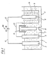
- Figure 1 is a schematic view of an embodiment of the invention;
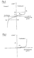
- FIG. 2 shows a diagram which shows the dissolution rate of the nickel anode of the second container and the deposition rate of the nickel at the cathode of the second container as a function of the current density at the surface of the anode or cathode; and
- Figure 3 is a diagram corresponding to Figure 2, but showing the deposition rate of zinc instead of nickel on the cathode of the second container.
Gemäß Figur 1 besteht die Vorrichtung im wesentlichen aus einem ersten Behälter 1 und einem zweiten Behälter 2, in denen jeweils eine Kathode 3 bzw. 4 und eine Anode 5 bzw. 6 angeordnet sind.According to FIG. 1, the device essentially consists of a
Der Behälter 1 ist mit dem Beschichtungsbad 7 gefüllt, wobei das im Behälter 1 durch die Metallabscheidung an der Kathode 3 an Elektrolyt verarmte Beschichtungsbad 7 dem Behälter 2 über eine Leitung 8 zugeführt und nach der Anreicherung des Elektrolyten im Behälter 2 über eine Umwälzleitung 9 mit einer Pumpe zu dem Behälter 1 wieder zurücktransportiert wird.The
An eine Gleichstromquelle 10 ist die Kathode 3 des Behälters 1 und die Anode 6 des Behälters 2 jeweils über eine Leitung 11 bzw. 12 angeschlossen. Die Kathode 4 des Behälters 2 ist mit der Anode 5 des Behälters 1 über eine elektrische Leitung 13 verbunden. Statt dieser Schaltung in Reihe kann auch eine solche Schaltung getroffen sein, daß der Strom im Bad des Behälters 2 unabhängig von dem Strom im Bad des Behälters 1 eingeschaltet bzw. die Stromstärke im Bad des Behälters 2 unabhängig von der Stromstärke im Bad des Behälters 1 eingestellt werden kann.The
Die Kathode 3 des Behälters 1 wird durch das zu beschichtende Werkstück, also beispielsweise durch die Zylinder einer Hubkolbenbrennkraftmaschine gebildet, deren Laufflächen beschichtet werden sollen. Die Anode 5 besteht aus Blei und ist unlöslich.The
Das Beschichtungsbad 7 wird durch ein Nickelsulfatbad gebildet, beispielsweise mit einer Nickelsalzkonzentration von 700 Gramm/Liter Wasser. In dem Bad 7 kann Siliziumkarbid aufgeschlämmt sein, beispielsweise 30 Gramm/Liter. Für eine optimale; gleichmäßige Nickelabscheidung an der Werkstückkathode 3 wird ein pH-Wert des Beschichtungsbades 7 von 3 bis 4 angestrebt.The
Die Kathode 4 des Behälters 2 ist porös, beispielsweise gitterförmig ausgebildet und besteht aus einem leitenden Metall, z. B. einem Stahlgewebe, während die Anode 6 des Behälters 2 aus Nickel gebildet ist. Die Kathode 4 ist zylindrisch ausgebildet und konzentrisch um die Anode 6 angeordnet, so daß die Oberfläche der Kathode 4 des Behälters 2 um ein Vielfaches, beispielsweise 50 bis 200 Mal größer ist als die Oberfläche der Anode 6 des Behälters 2.The
Bei der Nickelbeschichtung der Zylinderlaufflächen von Kolbenbrennkraftmaschinen fließt in dem Bad der Behälter 1 und 2 ein Strom von beispielsweise 2 bis 3 Kilo-Ampere.With the nickel coating of the cylinder running surfaces of piston internal combustion engines, a current of, for example, 2 to 3 kilo amperes flows in the bath of the
Bei dem erfindungsgemäßen Verfahren geht von der Nickelanode 6 in dem Behälter 2 praktisch so viel Nickel in Lösung, wie sich an der Kathode 3 bzw. dem Werkstück im Behälter 1 abscheidet. Wesentlich ist nun bei dem erfindungsgemäßen Verfahren vor allem, daß sich das von der Nickelanode 6 im Behälter 2 in Lösung gegangene Nickel nicht wieder an der der Anode 6 zugeordneten Kathode 4 des Behälters 2 abscheidet, sondern weitestgehend über die Umwälzleitung 9 dem Behälter 1 zugeführt wird. Dies wird erfindungsgemäß durch die um ein Vielfaches größere Oberfläche der Kathode 4 gegenüber der Anode 6 des Behälters 2 erreicht.In the method according to the invention, practically as much nickel goes into solution from the
Wie dem Diagramm der Figur 2 zu entnehmen, wird die Auflösungsgeschwindigkeit des Nickels an der Anode 6 des Behälters 2 und die Abscheidungsgeschwindigkeit des Nickels an der Kathode 4 des Behälters 2 durch die Stromdichte A/dm2 an der Anode 6 bzw. der Kathode 4 des Behälters 2 bestimmt. Daß heißt, da die Oberfläche der Anode 6 des Behälters 2 um ein Vielfaches kleiner ist als die Oberfläche der Kathode 4 des Behälters 2, ist die Stromdichte an der Oberfläche der Anode 6 um ein Vielfaches größer als an der Oberfläche der Kathode 4 des zweiten Behälters 1.As can be seen from the diagram in FIG. 2, the dissolution rate of the nickel at the
An der Kathode 4 des zweiten Behälters 2 herrscht also eine relativ geringe Stromdichte von beispielsweise 1 A/dm2, so daß die Nickelabscheidung an der Kathode 4 des Behälters 2 geringfügig ist, während an der Anode 6 des Behälters 2 eine relativ große Stromdichte von beispielsweise 50 A/dm2 und damit eine entsprechend hohe Auflösungsgeschwindigkeit des Nickels vorliegt. Das Größenverhältnis zwischen den Oberflächender Anode 6 und der Kathode 4 des Behälters 2 findet ihre Grenze einmal darin, daß die Größe der Kathode 4 aus praktischen Gründen nicht beliebig groß gewählt werden kann, ferner in der folgenden Sekundärreaktion.

Das heißt, durch die Elektrolyse der gemäß der Gleichung I gebildeten Schwefelsäure bzw. des Wassers.That is, by the electrolysis of the sulfuric acid or water formed according to equation I.
Die Stromdichte an der Anode 6 zur Auflösung derselben muß also unterhalb des Wertes bleiben, bei dem die Wasserelektrolyse einzusetzen beginnt, wie in dem Diagramm der Figur 2 durch die Gerade 02 veranschaulicht.The current density at the
Neben der Bildung von neuem Nickelelektrolyten zur Regenerierung des Beschichtungsbades dient die erfindungsgemäße Vorrichtung zugleich zur selektiven Reinigung des Beschichtungsbades von solchen metallischen Verunreinigungen, die bei vorgegebener Stromdichte eine höhere Abscheidungsgeschwindigkeit an der Kathode 4 des Behälters 2 aufweisen als Nickel, z. B. von Zinkionen. Aus Figur 3 ist ersichtlich, daß bei einer Stromdichte von beispielsweise 1 A/dm2 an der Oberfläche der Kathode 4 des Behälters 2 die Abscheidungsgeschwindigkeit von Zink um ein Vielfaches größer ist als von Nickel, so daß gegenüber Nickel bevorzugt im Beschichtungsbad enthaltenes Zink und andere Verunreinigungen an der Kathode 4 des Behälters 2 abgeschieden werden, d. h. das Beschichtungsbad wird selektiv gereinigt, ohne daß es zur Nickelabscheidung kommt.In addition to the formation of new nickel electrolyte for the regeneration of the coating bath, the device according to the invention also serves for the selective cleaning of the coating bath from such metallic impurities which, at a given current density, have a higher deposition rate at the
Die lösliche Nickelanode 6 im Behälter 2 ist zweckmäßig von einem porösen Magnetfilter 14 umgeben, um zu verhindern, daß Nickelflitter, die beim Auflösen der Anode 6 entstehen können, in das Beschichtungsbad 7 gelangen. Derartige Magnetfilter sind an sich bekannt (vgl. DE-OS 3 007 161The
Die Vorteile des erfindungsgemäßen Verfahrens sind insbesondere darin zu sehen, daß ein Nachdosieren des Elektrolyten des Beschichtungsbades entfällt, der pH-Wert des Beschichtungsbades über längere Zeit konstant bleibt und das Beschichtungsbad zugleich selektiv gereinigt wird. Aus diesen Vorteilen resultiert eine problemlose Badführung.The advantages of the method according to the invention are to be seen in particular in that there is no need to replenish the electrolyte in the coating bath, the pH of the coating bath remains constant over a long period of time and the coating bath is simultaneously cleaned selectively. These advantages result in problem-free bathroom management.
Claims (8)
Applications Claiming Priority (2)
| Application Number | Priority Date | Filing Date | Title |
|---|---|---|---|
| DE3144128 | 1981-11-06 | ||
| DE3144128A DE3144128C1 (en) | 1981-11-06 | 1981-11-06 | Device for the galvanic deposition of a metal on a metallic workpiece |
Publications (2)
| Publication Number | Publication Date |
|---|---|
| EP0079032A1 EP0079032A1 (en) | 1983-05-18 |
| EP0079032B1 true EP0079032B1 (en) | 1987-03-04 |
Family
ID=6145791
Family Applications (1)
| Application Number | Title | Priority Date | Filing Date |
|---|---|---|---|
| EP82110104A Expired EP0079032B1 (en) | 1981-11-06 | 1982-11-03 | Apparatus for electroplating a metallic workpiece |
Country Status (2)
| Country | Link |
|---|---|
| EP (1) | EP0079032B1 (en) |
| DE (2) | DE3144128C1 (en) |
Families Citing this family (2)
| Publication number | Priority date | Publication date | Assignee | Title |
|---|---|---|---|---|
| US4933051A (en) * | 1989-07-24 | 1990-06-12 | Omi International Corporation | Cyanide-free copper plating process |
| US6413390B1 (en) * | 2000-10-02 | 2002-07-02 | Advanced Micro Devices, Inc. | Plating system with remote secondary anode for semiconductor manufacturing |
Citations (1)
| Publication number | Priority date | Publication date | Assignee | Title |
|---|---|---|---|---|
| GB1273978A (en) * | 1968-07-08 | 1972-05-10 | Nat Res Dev | Improvements in or relating to electrolytic deposition of metals |
Family Cites Families (4)
| Publication number | Priority date | Publication date | Assignee | Title |
|---|---|---|---|---|
| NL71231C (en) * | 1948-04-22 | |||
| DE1496966A1 (en) * | 1966-12-29 | 1969-08-14 | Peach Arthur Leslie | Plating process |
| FR1582093A (en) * | 1968-05-31 | 1969-09-26 | ||
| DE1926974A1 (en) * | 1969-05-23 | 1970-11-26 | Siemens Ag | Device for selective cleaning of galvanic baths |
-
1981
- 1981-11-06 DE DE3144128A patent/DE3144128C1/en not_active Expired
-
1982
- 1982-11-03 EP EP82110104A patent/EP0079032B1/en not_active Expired
- 1982-11-03 DE DE8282110104T patent/DE3275563D1/en not_active Expired
Patent Citations (1)
| Publication number | Priority date | Publication date | Assignee | Title |
|---|---|---|---|---|
| GB1273978A (en) * | 1968-07-08 | 1972-05-10 | Nat Res Dev | Improvements in or relating to electrolytic deposition of metals |
Also Published As
| Publication number | Publication date |
|---|---|
| DE3275563D1 (en) | 1987-04-09 |
| DE3144128C1 (en) | 1983-06-09 |
| EP0079032A1 (en) | 1983-05-18 |
Similar Documents
| Publication | Publication Date | Title |
|---|---|---|
| EP0878561B1 (en) | Process and apparatus for the regeneration of tin plating solutions | |
| DE1496886A1 (en) | Method and device for the preparation of metal treatment solutions | |
| EP0638664A1 (en) | Process and apparatus for regenerating solutions containing metal ions and sulfuric acid | |
| DE10261493A1 (en) | Anode for electroplating | |
| EP1831435B1 (en) | Method for continuously operating acid or alkaline zinc or zinc alloy baths | |
| DE2759952C2 (en) | Process for the operational control of a copper plating bath that works without an external power supply | |
| EP0079032B1 (en) | Apparatus for electroplating a metallic workpiece | |
| DE19736350C1 (en) | Process for regulating the concentration of substances in electrolytes and device for carrying out the process | |
| EP0240589B1 (en) | Process and apparatus for regenerating an electroless copper-plating bath | |
| DE2713392C2 (en) | Process for the preparation of metal complex solutions | |
| EP0575699A2 (en) | Process and apparatus for regenerating metal ions and sulfuric acid containing aqueous solutions and use thereof | |
| DE4405741C1 (en) | Electrolytic deposition of metal coating | |
| DE4407448C2 (en) | Electrolysis process for regenerating an iron (III) chloride or iron (III) sulfate solution, in particular for spray etching steel | |
| DE102021002197A1 (en) | Device and method for coating a component or semi-finished product with a chromium layer | |
| EP0054695B1 (en) | Method for the galvanic manufacture of whiskers and apparatus for carrying out this method | |
| DE2360834C3 (en) | Bath and process for the galvanic deposition of palladium layers | |
| DE4315411C2 (en) | Process for the regeneration of spent chromic acid solutions | |
| DE4031979A1 (en) | Equipment for removing contaminants from chrome plating baths - comprises membrane tank with one or more membrane cylinders of sintered ceramic, clarifying tank and pumped circulation systems | |
| DE4229917C1 (en) | Electrolytic bath for meter coating - has sec. anode contg. alkaline or ammonium soln. with acid added to electrolyte to compensate for pH rise | |
| DE4218916C2 (en) | Use of a grid anode for electrolytic detoxification or regeneration of an aqueous solution containing cyanide | |
| EP0483937A1 (en) | Electrolytic cell, process and its use | |
| DE2836720C2 (en) | Process for the continuous electrolytic regeneration of a washing solution containing silver cyanide which occurs during electroplating processes and a device for carrying out the process | |
| DE3330838C2 (en) | ||
| DE2617991C3 (en) | Method and device for treating waste water | |
| DE19653273C2 (en) | A method for recovering at least one metal deposited on a substrate |
Legal Events
| Date | Code | Title | Description |
|---|---|---|---|
| PUAI | Public reference made under article 153(3) epc to a published international application that has entered the european phase |
Free format text: ORIGINAL CODE: 0009012 |
|
| 17P | Request for examination filed |
Effective date: 19830301 |
|
| AK | Designated contracting states |
Designated state(s): DE FR GB IT SE |
|
| GRAA | (expected) grant |
Free format text: ORIGINAL CODE: 0009210 |
|
| AK | Designated contracting states |
Kind code of ref document: B1 Designated state(s): DE FR GB IT SE |
|
| REF | Corresponds to: |
Ref document number: 3275563 Country of ref document: DE Date of ref document: 19870409 |
|
| ET | Fr: translation filed | ||
| ITF | It: translation for a ep patent filed |
Owner name: STUDIO JAUMANN |
|
| PG25 | Lapsed in a contracting state [announced via postgrant information from national office to epo] |
Ref country code: SE Effective date: 19871104 |
|
| PLBE | No opposition filed within time limit |
Free format text: ORIGINAL CODE: 0009261 |
|
| STAA | Information on the status of an ep patent application or granted ep patent |
Free format text: STATUS: NO OPPOSITION FILED WITHIN TIME LIMIT |
|
| 26N | No opposition filed | ||
| GBPC | Gb: european patent ceased through non-payment of renewal fee | ||
| PG25 | Lapsed in a contracting state [announced via postgrant information from national office to epo] |
Ref country code: FR Free format text: LAPSE BECAUSE OF NON-PAYMENT OF DUE FEES Effective date: 19880729 |
|
| PG25 | Lapsed in a contracting state [announced via postgrant information from national office to epo] |
Ref country code: DE Effective date: 19880802 |
|
| REG | Reference to a national code |
Ref country code: FR Ref legal event code: ST |
|
| PG25 | Lapsed in a contracting state [announced via postgrant information from national office to epo] |
Ref country code: GB Effective date: 19881121 |
|
| EUG | Se: european patent has lapsed |
Ref document number: 82110104.5 Effective date: 19880913 |