EP0078758B1 - Perfectionnements aux réducteurs de couple - Google Patents
Perfectionnements aux réducteurs de couple Download PDFInfo
- Publication number
- EP0078758B1 EP0078758B1 EP19820450016 EP82450016A EP0078758B1 EP 0078758 B1 EP0078758 B1 EP 0078758B1 EP 19820450016 EP19820450016 EP 19820450016 EP 82450016 A EP82450016 A EP 82450016A EP 0078758 B1 EP0078758 B1 EP 0078758B1
- Authority
- EP
- European Patent Office
- Prior art keywords
- sector
- hub
- wheel
- box
- controlled
- Prior art date
- Legal status (The legal status is an assumption and is not a legal conclusion. Google has not performed a legal analysis and makes no representation as to the accuracy of the status listed.)
- Expired
Links
- 239000003638 chemical reducing agent Substances 0.000 title claims description 43
- 230000002093 peripheral effect Effects 0.000 claims description 7
- 238000005461 lubrication Methods 0.000 claims description 2
- 238000003754 machining Methods 0.000 description 7
- 238000012423 maintenance Methods 0.000 description 5
- 238000005452 bending Methods 0.000 description 3
- 230000008878 coupling Effects 0.000 description 2
- 238000010168 coupling process Methods 0.000 description 2
- 238000005859 coupling reaction Methods 0.000 description 2
- 238000009434 installation Methods 0.000 description 2
- 210000000056 organ Anatomy 0.000 description 2
- 230000005540 biological transmission Effects 0.000 description 1
- 238000006243 chemical reaction Methods 0.000 description 1
- 230000000295 complement effect Effects 0.000 description 1
- 239000000470 constituent Substances 0.000 description 1
- 230000001186 cumulative effect Effects 0.000 description 1
- 239000000428 dust Substances 0.000 description 1
- 230000000694 effects Effects 0.000 description 1
- 239000004519 grease Substances 0.000 description 1
- 238000000034 method Methods 0.000 description 1
- 238000000465 moulding Methods 0.000 description 1
- 238000007789 sealing Methods 0.000 description 1
- 238000012795 verification Methods 0.000 description 1
Images
Classifications
-
- F—MECHANICAL ENGINEERING; LIGHTING; HEATING; WEAPONS; BLASTING
- F16—ENGINEERING ELEMENTS AND UNITS; GENERAL MEASURES FOR PRODUCING AND MAINTAINING EFFECTIVE FUNCTIONING OF MACHINES OR INSTALLATIONS; THERMAL INSULATION IN GENERAL
- F16H—GEARING
- F16H1/00—Toothed gearings for conveying rotary motion
- F16H1/02—Toothed gearings for conveying rotary motion without gears having orbital motion
- F16H1/04—Toothed gearings for conveying rotary motion without gears having orbital motion involving only two intermeshing members
- F16H1/12—Toothed gearings for conveying rotary motion without gears having orbital motion involving only two intermeshing members with non-parallel axes
- F16H1/16—Toothed gearings for conveying rotary motion without gears having orbital motion involving only two intermeshing members with non-parallel axes comprising worm and worm-wheel
-
- F—MECHANICAL ENGINEERING; LIGHTING; HEATING; WEAPONS; BLASTING
- F16—ENGINEERING ELEMENTS AND UNITS; GENERAL MEASURES FOR PRODUCING AND MAINTAINING EFFECTIVE FUNCTIONING OF MACHINES OR INSTALLATIONS; THERMAL INSULATION IN GENERAL
- F16K—VALVES; TAPS; COCKS; ACTUATING-FLOATS; DEVICES FOR VENTING OR AERATING
- F16K31/00—Actuating devices; Operating means; Releasing devices
- F16K31/44—Mechanical actuating means
- F16K31/53—Mechanical actuating means with toothed gearing
- F16K31/54—Mechanical actuating means with toothed gearing with pinion and rack
Definitions
- the present invention relates to worm gear reducers intended in particular for manual or motorized control of industrial valves.
- This type of reducer generally comprises an endless screw engaged with either a toothed sector for fractional turn reducers, or a toothed wheel for full turn reducers.
- the two engaged parts have their orthogonal axes and are held in place by a housing or enclosure constituted by two complementary parts assembled together in front of them after installation inside the worm and the sector or the wheel.
- a start device intended to delimit the angular movement of the sector and generally consisting of two screws arranged at the periphery of the housing and adjustable from the outside.
- said enclosure comprises a hollow body forming a mounting base on the valve, for example, to be actuated and a cover attached to the body on the side opposite to the valve.
- the enclosure comprises a base in the form of a fixing flange and a hollow body in the form of a bell which covers the entire mechanism, these two parts integrally constituting a closed enclosure excluding the two circular openings arranged in the axis of the controlled shaft and serving as a bearing for the hollow hub of the toothed wheel.
- a base in the form of a fixing flange
- a hollow body in the form of a bell which covers the entire mechanism
- this axis is the seat of a force having in particular a radial component balanced by the reaction of the device maintaining the axis of said sector or wheel.
- the sector (or the wheel) generally consists of a hollow cylindrical axis which fits onto the rod transmitting the force and a portion of disc (or disc) coaxial said axis and of configuration practically symmetrical with respect to a plane perpendicular to the axis of the sector (or of the wheel).
- the arrangements adopted comprise either two bearings, one secured to the base and the other secured, as the case may be, either to the removable cover, or to the bell-shaped enclosure covering the mechanism, as illustrated. for example by the document DE-A-2.133.237 already cited.
- the position indicator is in the form of a simple flat disc with an index, which implies an additional weather-sealing system generally taking the form of a seal. placed at the level of the outer bearing of the sector axis.
- the object of the present invention is to eliminate these drawbacks by proposing a new mounting structure for torque reducers. reducing precise machining operations, making it easier to assemble the components as well as subsequent maintenance operations.
- Torque reducer of the type comprising a toothed wheel or sector integral in rotation with a shaft to be controlled and comprising a hollow hub connected to the peripheral toothing, a worm screw moved manually or by motor in tangential engagement with said toothing and axis orthogonal to the axis of said wheel or sector and a housing or enclosure enclosing the above organs, open on the side opposite the controlled shaft, the opening being closed by a removable cover and at least part of which determines the surfaces bearings supporting the axis of the wheel or sector coaxially with said driven shaft, said reducer being characterized in that said hollow hub is connected to the peripheral toothing by means of a veil shaped so as to form between the hub and the teeth an annular space in which is disposed a single bearing for centering and centering the hub forming an integral part of the body of said housing, the radial result of the force transmitted by the screw the wheel or sector applying substantially in the central part of said bearing.
- This arrangement has the substantial advantage of eliminating any bending torques because the radial component of the force to which the wheel or the sector is subjected applies in the central part of the bearing.
- the latter can therefore be very significantly reduced in length, which facilitates machining and therefore reduces friction.
- the reduction gear according to the invention advantageously comprises a rotation indicator integral with the external face of said cover which is constituted by a substantially plane disc integral in rotation with the wheel or sector, said housing body being intended to be attached on the body of the controlled device.
- the gearbox housing therefore has only one main part which is only machined, the cover being a simple closing disc
- the opening of the main body in a weatherproof manner and allowing direct and instant access to the interior of the reducer to ensure its maintenance and verification without any disassembly of the essential organs of the reducer.
- this can advantageously be provided with adjustable stop screws for limiting the travel of the sector, carried by the sector, on the cover side, and cooperating with fixed projections integral with the housing body.
- This system for adjusting the travel of the sector is thus entirely inside the case unlike current systems and very easily accessible by simply removing the cover.
- the housing no longer has to be specially machined to receive traditional screw-stops, the same housing can be used for different reducers with full turn, or fraction of turn.
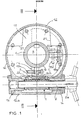
- the reduction gear shown in the drawings is a fraction-turn reduction gear comprising an endless screw 1 secured to an axis 2, one end of which 2a is keyed onto a rotation drive member not shown (a flywheel or a motor for example) .
- the screw 1 is engaged with the teeth 3 of a quarter-turn sector 4 integral in rotation with a controlled shaft 5 actuating for example a valve.
- Sector 4 is integral with a cylindrical hub 6 keyed to the end of the shaft 5 and consists of a web 7 inclined on the axis of the hub 6, forming an integral part of the latter and the peripheral part of which constitutes teeth 3.
- the general plane of the web 7 is inclined by about fifty degrees about the axis of the hub 6, the junction of the web 7 with the hub 6 being offset from the center of the hub.
- annular space 8 is formed between the teeth 3 and the hub 6, under the veil 7, an annular space 8 in the form of a wedge whose fundamental interest will appear later.
- the hub 6 is supported and centered by a single bearing 9 shaped on a tubular extension 10 integral with a base 11 intended to be attached and fixed by any suitable means to a body of a valve for example, controlled by the shaft 5 .
- the base 11 is itself extended by an external envelope 12 forming a casing and constituting the main body of the enclosure of the reducer.
- the parts 10, 11 and 12 are of course produced in one piece by molding and then machining.
- the height of the main body 12 of said enclosure corresponds substantially to that of the hub 6, while the length of the single bearing 9 is very small in comparison with the lengths of the single bearing of known reducers or of the cumulative length of the two bearings arranged on one side and on the other side of the sector other known types of reducers, as was pointed out above.
- the central part of said bearing 9 is perpendicular to the normal component 13 of the force transmitted by the screw 1 to sector 4 thanks to the possibility of placing the bearing 9 in the annular corner space 8.
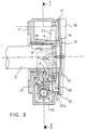
- the screw 1 is held and centered in an extension 12a (Fig. 1) of the body 12 in the manner conventional using sleeves 14 with added needle bearings and fixed on said body 12a.
- the body 12 is open on the side opposite the base 11.
- a cylindrical flange 12b is provided coaxial with the hub 6.
- the circular opening thus determined is closed using a substantially flat cover 15 removably fixed at the end of the shaft 5 for example.
- the cover 15 is fitted thanks to an internal circular shoulder 16 on the end of the hub 6 while the peripheral rim of the cover has a return 17 conforming to the rim 12b in order to make the reducer tight against dust and bad weather. A slight clearance nevertheless remains between the cover 15 and the fixed rim 12b so as not to impede the rotation of the cover 15 which carries on its outer face a rotation indicator 18, in the well known manner.
- the system for adjusting the angular movement of sector 4 consists of two stop screws 19a and 19b mounted adjustable on two lugs 20a and 20b secured to sector 4 (cover side 15) and offset by 90 ° between them.
- abutment screws 19a, 19b cooperate with fixed projections 21 molded from the main body 12 and arranged accordingly inside the enclosure.
- This arrangement of the projections 21 is moreover such that the quarter-turn sector 4 could be instantly replaced by a half-turn sector provided, in its central part with an ear such as the ear 20a carrying a first stop screw such as 19a and a second abutment screw such as the screw shown in 19c disposed head to tail with the first and thus ensuring the precise 180 ° movement of the latter sector.
- the reducer shown and described above has a number of significant advantages over known reducers.
- the radial component 13 of the force to which the sector 4 is subjected in operation applies, thanks to the lateral offset of the web 7, in a zone located between the two ends of the single bearing 9, the length of the latter can be significantly reduced since there is no longer any effect of bending torque exerted on said bearing.
- the friction is reduced accordingly, however, that the machining of the bearing is less important and also less tight due to the excellent balance of forces that can be obtained with such an arrangement of the bearing.
- the reduction gear according to the invention also has a reduced height corresponding to the length of the hub 6 substantially, which can be reduced to the strict minimum necessary to ensure proper coupling with the shaft to be controlled 5.
- adjustable stop screws 19a, 19b, 19c inside, on sector 4 eliminates the need to machine the gearbox housing which can be standard and used for various types of gearboxes (full turn, quarter turn , half-turn, any fraction of a turn).
- a lubrication reserve for the screw 1 by producing an internal rib 22 retaining secured to the base 11, in line with the contact zone between the screw 1 and the toothing 3, the reduction gear being arranged with the axis of its vertical hub above the controlled valve.
- This rib 22 also performs the role of a squeegee with respect to the flank of the toothing 3 and confines the grease in its zone of use.
- the veil 7 may have another conformation (L-shaped section for example) insofar as there is produced, between the teeth 3 and the hub 6, an annular space making it possible to house the single bearing 9.
- L-shaped section for example
- the sector 4 could be arranged in the opposite direction on the end of the shaft 5 in which case the support bearing would be shaped on an internal extension of an enclosure body attached to a base similar to the base 11, said body enveloping the reduction gear members in the manner of body 12 and being closed off at the end of the shaft 5 by a disc-cover similar to cover 15 but of diameter reduced substantially to the outside diameter of the hub 6.
- the reduction gear according to the invention is used for controlling any device comprising a shaft whose rotation must be controlled, such as an industrial valve for example, but can also constitute the essential part of a mechanical jack.
Landscapes
- Engineering & Computer Science (AREA)
- General Engineering & Computer Science (AREA)
- Mechanical Engineering (AREA)
- General Details Of Gearings (AREA)
- Gear Transmission (AREA)
- Gears, Cams (AREA)
Applications Claiming Priority (2)
| Application Number | Priority Date | Filing Date | Title |
|---|---|---|---|
| FR8120772A FR2515764A1 (fr) | 1981-11-04 | 1981-11-04 | Perfectionnements aux reducteurs de couple |
| FR8120772 | 1981-11-04 |
Publications (2)
| Publication Number | Publication Date |
|---|---|
| EP0078758A1 EP0078758A1 (fr) | 1983-05-11 |
| EP0078758B1 true EP0078758B1 (fr) | 1986-08-13 |
Family
ID=9263731
Family Applications (1)
| Application Number | Title | Priority Date | Filing Date |
|---|---|---|---|
| EP19820450016 Expired EP0078758B1 (fr) | 1981-11-04 | 1982-11-03 | Perfectionnements aux réducteurs de couple |
Country Status (4)
| Country | Link |
|---|---|
| EP (1) | EP0078758B1 (https=) |
| DE (1) | DE3272605D1 (https=) |
| FR (1) | FR2515764A1 (https=) |
| SU (1) | SU1232138A3 (https=) |
Families Citing this family (1)
| Publication number | Priority date | Publication date | Assignee | Title |
|---|---|---|---|---|
| FR2975363B1 (fr) * | 2011-05-19 | 2013-05-17 | Jtekt Europe Sas | Direction de vehicule automobile a assistance electrique |
Family Cites Families (6)
| Publication number | Priority date | Publication date | Assignee | Title |
|---|---|---|---|---|
| US1450660A (en) * | 1920-10-22 | 1923-04-03 | Alvan H Alberger | Driving mechanism for agitators |
| US1496379A (en) * | 1923-09-20 | 1924-06-03 | Reid John | Worm and gear power |
| US1564742A (en) * | 1923-10-22 | 1925-12-08 | Cleveland Worm And Gear Compan | Worm-gear reduction unit |
| GB979500A (en) * | 1963-02-06 | 1965-01-06 | King Of Prussia Res And Dev Co | Improvements in or relating to valves for controlling fluid flow |
| DE2133237A1 (de) * | 1971-07-03 | 1973-01-11 | Limitorque Gmbh | Vorgelege zur betaetigung von schiebern, ventilen oder dergleichen |
| US4084447A (en) * | 1976-04-01 | 1978-04-18 | Westran Corporation | Valve actuator |
-
1981
- 1981-11-04 FR FR8120772A patent/FR2515764A1/fr active Granted
-
1982
- 1982-11-03 EP EP19820450016 patent/EP0078758B1/fr not_active Expired
- 1982-11-03 DE DE8282450016T patent/DE3272605D1/de not_active Expired
- 1982-11-04 SU SU823514797A patent/SU1232138A3/ru active
Also Published As
| Publication number | Publication date |
|---|---|
| DE3272605D1 (en) | 1986-09-18 |
| SU1232138A3 (ru) | 1986-05-15 |
| EP0078758A1 (fr) | 1983-05-11 |
| FR2515764B1 (https=) | 1984-01-20 |
| FR2515764A1 (fr) | 1983-05-06 |
Similar Documents
| Publication | Publication Date | Title |
|---|---|---|
| FR2801652A1 (fr) | Armature ajustable pour un systeme de deplacement a pivot d'une premiere piece d'articulation par rapport a une deuxieme piece d'articulation | |
| FR2677416A1 (fr) | Petit moteur equipe d'un mecanisme reducteur a vis. | |
| CH652462A5 (fr) | Actuateur lineaire a moteur electrique. | |
| FR2712852A1 (fr) | Essieu arrière pour un tracteur. | |
| EP2469358B1 (fr) | Mécanisme de transmission de mouvements axiaux et rotatifs entre deux axes décalés | |
| EP0686536B1 (fr) | Moto-réducteur comprenant un carter creux muni d'une plaque de fermeture, notamment moto-réducteur d'essuyage | |
| EP0686537B1 (fr) | Moto-réducteur comprenant un carter creux muni d'une plaque de fermeture, notamment moto-réducteur d'essuyage | |
| EP4185483A1 (fr) | Dispositif de transmission et engin roulant équipé d'un tel dispositif de transmission | |
| EP0078758B1 (fr) | Perfectionnements aux réducteurs de couple | |
| FR2580760A1 (fr) | Procede et dispositif pour la reduction du jeu de fonctionnement radial entre deux pieces engagees l'une dans l'autre et animees d'un mouvement de rotation l'une par rapport a l'autre et reducteur de vitesse " sans jeu " obtenu a l'aide de ce procede | |
| FR2745250A1 (fr) | Motoreducteur fixe par le couvercle | |
| EP0236650A1 (fr) | Dispositif d'entraînement de deux arbres alignés, avec mécanisme différentiel, notamment deux arbres de transmission reliés à deux roues arrière de véhicule | |
| FR3001270A3 (fr) | "differentiel de transmission comportant des moyens de friction perfectionnes" | |
| FR2590633A1 (fr) | Dispositif de fixation reglable, en particulier pour l'assemblage d'ecrans video | |
| EP0649971B1 (fr) | Dispositif de renvoi d'angle pour volet roulant | |
| FR2704287A1 (fr) | Dispositif de transmission. | |
| EP0132171B1 (fr) | Dispositif de commande d'un miroir de rétroviseur extérieur de l'intérieur d'un véhicule | |
| EP0059657A1 (fr) | Valve de servodirection à montage simplifié | |
| FR2747169A1 (fr) | Boitier de transformation de mouvement, rotatif-alternatif, ou inversement avec changement possible de direction, de frequence, de phase et d'amplitude | |
| FR2744679A1 (fr) | Transmission de vehicule equipee d'un ralentisseur electrique | |
| FR2566595A3 (fr) | Groupe d'entrainement comportant un moteur de commande de preference electrique, comportant une vis de reglage bloquee dans sa position de service | |
| FR2538063A1 (fr) | Dispositif de transmission de mouvement a roue dentee et vis sans fin, et son application a une installation de positionnement d'antenne | |
| FR2968617A1 (fr) | Installation d'entrainement notamment pour un dispositif d'essuie-glace de vehicule | |
| FR2625543A1 (fr) | Nouveau clapet pour canalisations | |
| FR2755461A1 (fr) | Cremone monodirectionnelle |
Legal Events
| Date | Code | Title | Description |
|---|---|---|---|
| PUAI | Public reference made under article 153(3) epc to a published international application that has entered the european phase |
Free format text: ORIGINAL CODE: 0009012 |
|
| AK | Designated contracting states |
Designated state(s): BE DE GB IT NL |
|
| 17P | Request for examination filed |
Effective date: 19831109 |
|
| GRAA | (expected) grant |
Free format text: ORIGINAL CODE: 0009210 |
|
| AK | Designated contracting states |
Kind code of ref document: B1 Designated state(s): BE DE GB IT NL |
|
| ITF | It: translation for a ep patent filed | ||
| REF | Corresponds to: |
Ref document number: 3272605 Country of ref document: DE Date of ref document: 19860918 |
|
| PLBE | No opposition filed within time limit |
Free format text: ORIGINAL CODE: 0009261 |
|
| STAA | Information on the status of an ep patent application or granted ep patent |
Free format text: STATUS: NO OPPOSITION FILED WITHIN TIME LIMIT |
|
| 26N | No opposition filed | ||
| PGFP | Annual fee paid to national office [announced via postgrant information from national office to epo] |
Ref country code: NL Payment date: 19871130 Year of fee payment: 6 |
|
| PG25 | Lapsed in a contracting state [announced via postgrant information from national office to epo] |
Ref country code: GB Effective date: 19891103 |
|
| PG25 | Lapsed in a contracting state [announced via postgrant information from national office to epo] |
Ref country code: BE Effective date: 19891130 |
|
| BERE | Be: lapsed |
Owner name: LES TECHNIQUES NOUVELLES DES FLUIDES S.A. Effective date: 19891130 |
|
| PG25 | Lapsed in a contracting state [announced via postgrant information from national office to epo] |
Ref country code: NL Effective date: 19900601 |
|
| GBPC | Gb: european patent ceased through non-payment of renewal fee | ||
| NLV4 | Nl: lapsed or anulled due to non-payment of the annual fee | ||
| PG25 | Lapsed in a contracting state [announced via postgrant information from national office to epo] |
Ref country code: DE Effective date: 19900801 |