EP0078421B1 - Adaptive control system for machine tool or the like - Google Patents
Adaptive control system for machine tool or the like Download PDFInfo
- Publication number
- EP0078421B1 EP0078421B1 EP82109474A EP82109474A EP0078421B1 EP 0078421 B1 EP0078421 B1 EP 0078421B1 EP 82109474 A EP82109474 A EP 82109474A EP 82109474 A EP82109474 A EP 82109474A EP 0078421 B1 EP0078421 B1 EP 0078421B1
- Authority
- EP
- European Patent Office
- Prior art keywords
- spindle
- bearings
- pressure
- thrust
- adjusting
- Prior art date
- Legal status (The legal status is an assumption and is not a legal conclusion. Google has not performed a legal analysis and makes no representation as to the accuracy of the status listed.)
- Expired
Links
Images

Classifications
-
- F—MECHANICAL ENGINEERING; LIGHTING; HEATING; WEAPONS; BLASTING
- F16—ENGINEERING ELEMENTS AND UNITS; GENERAL MEASURES FOR PRODUCING AND MAINTAINING EFFECTIVE FUNCTIONING OF MACHINES OR INSTALLATIONS; THERMAL INSULATION IN GENERAL
- F16N—LUBRICATING
- F16N29/00—Special means in lubricating arrangements or systems providing for the indication or detection of undesired conditions; Use of devices responsive to conditions in lubricating arrangements or systems
- F16N29/02—Special means in lubricating arrangements or systems providing for the indication or detection of undesired conditions; Use of devices responsive to conditions in lubricating arrangements or systems for influencing the supply of lubricant
-
- B—PERFORMING OPERATIONS; TRANSPORTING
- B23—MACHINE TOOLS; METAL-WORKING NOT OTHERWISE PROVIDED FOR
- B23Q—DETAILS, COMPONENTS, OR ACCESSORIES FOR MACHINE TOOLS, e.g. ARRANGEMENTS FOR COPYING OR CONTROLLING; MACHINE TOOLS IN GENERAL CHARACTERISED BY THE CONSTRUCTION OF PARTICULAR DETAILS OR COMPONENTS; COMBINATIONS OR ASSOCIATIONS OF METAL-WORKING MACHINES, NOT DIRECTED TO A PARTICULAR RESULT
- B23Q11/00—Accessories fitted to machine tools for keeping tools or parts of the machine in good working condition or for cooling work; Safety devices specially combined with or arranged in, or specially adapted for use in connection with, machine tools
- B23Q11/12—Arrangements for cooling or lubricating parts of the machine
- B23Q11/121—Arrangements for cooling or lubricating parts of the machine with lubricating effect for reducing friction
-
- B—PERFORMING OPERATIONS; TRANSPORTING
- B23—MACHINE TOOLS; METAL-WORKING NOT OTHERWISE PROVIDED FOR
- B23Q—DETAILS, COMPONENTS, OR ACCESSORIES FOR MACHINE TOOLS, e.g. ARRANGEMENTS FOR COPYING OR CONTROLLING; MACHINE TOOLS IN GENERAL CHARACTERISED BY THE CONSTRUCTION OF PARTICULAR DETAILS OR COMPONENTS; COMBINATIONS OR ASSOCIATIONS OF METAL-WORKING MACHINES, NOT DIRECTED TO A PARTICULAR RESULT
- B23Q15/00—Automatic control or regulation of feed movement, cutting velocity or position of tool or work
- B23Q15/007—Automatic control or regulation of feed movement, cutting velocity or position of tool or work while the tool acts upon the workpiece
- B23Q15/12—Adaptive control, i.e. adjusting itself to have a performance which is optimum according to a preassigned criterion
-
- B—PERFORMING OPERATIONS; TRANSPORTING
- B23—MACHINE TOOLS; METAL-WORKING NOT OTHERWISE PROVIDED FOR
- B23Q—DETAILS, COMPONENTS, OR ACCESSORIES FOR MACHINE TOOLS, e.g. ARRANGEMENTS FOR COPYING OR CONTROLLING; MACHINE TOOLS IN GENERAL CHARACTERISED BY THE CONSTRUCTION OF PARTICULAR DETAILS OR COMPONENTS; COMBINATIONS OR ASSOCIATIONS OF METAL-WORKING MACHINES, NOT DIRECTED TO A PARTICULAR RESULT
- B23Q15/00—Automatic control or regulation of feed movement, cutting velocity or position of tool or work
- B23Q15/007—Automatic control or regulation of feed movement, cutting velocity or position of tool or work while the tool acts upon the workpiece
- B23Q15/18—Compensation of tool-deflection due to temperature or force
-
- F—MECHANICAL ENGINEERING; LIGHTING; HEATING; WEAPONS; BLASTING
- F01—MACHINES OR ENGINES IN GENERAL; ENGINE PLANTS IN GENERAL; STEAM ENGINES
- F01M—LUBRICATING OF MACHINES OR ENGINES IN GENERAL; LUBRICATING INTERNAL COMBUSTION ENGINES; CRANKCASE VENTILATING
- F01M5/00—Heating, cooling, or controlling temperature of lubricant; Lubrication means facilitating engine starting
-
- F—MECHANICAL ENGINEERING; LIGHTING; HEATING; WEAPONS; BLASTING
- F16—ENGINEERING ELEMENTS AND UNITS; GENERAL MEASURES FOR PRODUCING AND MAINTAINING EFFECTIVE FUNCTIONING OF MACHINES OR INSTALLATIONS; THERMAL INSULATION IN GENERAL
- F16C—SHAFTS; FLEXIBLE SHAFTS; ELEMENTS OR CRANKSHAFT MECHANISMS; ROTARY BODIES OTHER THAN GEARING ELEMENTS; BEARINGS
- F16C19/00—Bearings with rolling contact, for exclusively rotary movement
- F16C19/52—Bearings with rolling contact, for exclusively rotary movement with devices affected by abnormal or undesired conditions
- F16C19/525—Bearings with rolling contact, for exclusively rotary movement with devices affected by abnormal or undesired conditions related to temperature and heat, e.g. insulation
-
- F—MECHANICAL ENGINEERING; LIGHTING; HEATING; WEAPONS; BLASTING
- F16—ENGINEERING ELEMENTS AND UNITS; GENERAL MEASURES FOR PRODUCING AND MAINTAINING EFFECTIVE FUNCTIONING OF MACHINES OR INSTALLATIONS; THERMAL INSULATION IN GENERAL
- F16C—SHAFTS; FLEXIBLE SHAFTS; ELEMENTS OR CRANKSHAFT MECHANISMS; ROTARY BODIES OTHER THAN GEARING ELEMENTS; BEARINGS
- F16C25/00—Bearings for exclusively rotary movement adjustable for wear or play
- F16C25/06—Ball or roller bearings
- F16C25/08—Ball or roller bearings self-adjusting
-
- F—MECHANICAL ENGINEERING; LIGHTING; HEATING; WEAPONS; BLASTING
- F16—ENGINEERING ELEMENTS AND UNITS; GENERAL MEASURES FOR PRODUCING AND MAINTAINING EFFECTIVE FUNCTIONING OF MACHINES OR INSTALLATIONS; THERMAL INSULATION IN GENERAL
- F16C—SHAFTS; FLEXIBLE SHAFTS; ELEMENTS OR CRANKSHAFT MECHANISMS; ROTARY BODIES OTHER THAN GEARING ELEMENTS; BEARINGS
- F16C33/00—Parts of bearings; Special methods for making bearings or parts thereof
- F16C33/30—Parts of ball or roller bearings
- F16C33/66—Special parts or details in view of lubrication
- F16C33/6637—Special parts or details in view of lubrication with liquid lubricant
- F16C33/6659—Details of supply of the liquid to the bearing, e.g. passages or nozzles
- F16C33/667—Details of supply of the liquid to the bearing, e.g. passages or nozzles related to conditioning, e.g. cooling, filtering
-
- F—MECHANICAL ENGINEERING; LIGHTING; HEATING; WEAPONS; BLASTING
- F16—ENGINEERING ELEMENTS AND UNITS; GENERAL MEASURES FOR PRODUCING AND MAINTAINING EFFECTIVE FUNCTIONING OF MACHINES OR INSTALLATIONS; THERMAL INSULATION IN GENERAL
- F16C—SHAFTS; FLEXIBLE SHAFTS; ELEMENTS OR CRANKSHAFT MECHANISMS; ROTARY BODIES OTHER THAN GEARING ELEMENTS; BEARINGS
- F16C33/00—Parts of bearings; Special methods for making bearings or parts thereof
- F16C33/30—Parts of ball or roller bearings
- F16C33/66—Special parts or details in view of lubrication
- F16C33/6637—Special parts or details in view of lubrication with liquid lubricant
- F16C33/6659—Details of supply of the liquid to the bearing, e.g. passages or nozzles
- F16C33/6674—Details of supply of the liquid to the bearing, e.g. passages or nozzles related to the amount supplied, e.g. gaps to restrict flow of the liquid
-
- F—MECHANICAL ENGINEERING; LIGHTING; HEATING; WEAPONS; BLASTING
- F16—ENGINEERING ELEMENTS AND UNITS; GENERAL MEASURES FOR PRODUCING AND MAINTAINING EFFECTIVE FUNCTIONING OF MACHINES OR INSTALLATIONS; THERMAL INSULATION IN GENERAL
- F16N—LUBRICATING
- F16N29/00—Special means in lubricating arrangements or systems providing for the indication or detection of undesired conditions; Use of devices responsive to conditions in lubricating arrangements or systems
-
- F—MECHANICAL ENGINEERING; LIGHTING; HEATING; WEAPONS; BLASTING
- F16—ENGINEERING ELEMENTS AND UNITS; GENERAL MEASURES FOR PRODUCING AND MAINTAINING EFFECTIVE FUNCTIONING OF MACHINES OR INSTALLATIONS; THERMAL INSULATION IN GENERAL
- F16N—LUBRICATING
- F16N7/00—Arrangements for supplying oil or unspecified lubricant from a stationary reservoir or the equivalent in or on the machine or member to be lubricated
- F16N7/30—Arrangements for supplying oil or unspecified lubricant from a stationary reservoir or the equivalent in or on the machine or member to be lubricated the oil being fed or carried along by another fluid
- F16N7/32—Mist lubrication
- F16N7/34—Atomising devices for oil
-
- F—MECHANICAL ENGINEERING; LIGHTING; HEATING; WEAPONS; BLASTING
- F16—ENGINEERING ELEMENTS AND UNITS; GENERAL MEASURES FOR PRODUCING AND MAINTAINING EFFECTIVE FUNCTIONING OF MACHINES OR INSTALLATIONS; THERMAL INSULATION IN GENERAL
- F16C—SHAFTS; FLEXIBLE SHAFTS; ELEMENTS OR CRANKSHAFT MECHANISMS; ROTARY BODIES OTHER THAN GEARING ELEMENTS; BEARINGS
- F16C2322/00—Apparatus used in shaping articles
- F16C2322/39—General build up of machine tools, e.g. spindles, slides, actuators
-
- G—PHYSICS
- G05—CONTROLLING; REGULATING
- G05B—CONTROL OR REGULATING SYSTEMS IN GENERAL; FUNCTIONAL ELEMENTS OF SUCH SYSTEMS; MONITORING OR TESTING ARRANGEMENTS FOR SUCH SYSTEMS OR ELEMENTS
- G05B2219/00—Program-control systems
- G05B2219/30—Nc systems
- G05B2219/37—Measurements
- G05B2219/37344—Torque, thrust, twist, machining force measurement
-
- G—PHYSICS
- G05—CONTROLLING; REGULATING
- G05B—CONTROL OR REGULATING SYSTEMS IN GENERAL; FUNCTIONAL ELEMENTS OF SUCH SYSTEMS; MONITORING OR TESTING ARRANGEMENTS FOR SUCH SYSTEMS OR ELEMENTS
- G05B2219/00—Program-control systems
- G05B2219/30—Nc systems
- G05B2219/37—Measurements
- G05B2219/37431—Temperature
-
- G—PHYSICS
- G05—CONTROLLING; REGULATING
- G05B—CONTROL OR REGULATING SYSTEMS IN GENERAL; FUNCTIONAL ELEMENTS OF SUCH SYSTEMS; MONITORING OR TESTING ARRANGEMENTS FOR SUCH SYSTEMS OR ELEMENTS
- G05B2219/00—Program-control systems
- G05B2219/30—Nc systems
- G05B2219/49—Nc machine tool, till multiple
- G05B2219/49043—Control of lubrication
-
- G—PHYSICS
- G05—CONTROLLING; REGULATING
- G05B—CONTROL OR REGULATING SYSTEMS IN GENERAL; FUNCTIONAL ELEMENTS OF SUCH SYSTEMS; MONITORING OR TESTING ARRANGEMENTS FOR SUCH SYSTEMS OR ELEMENTS
- G05B2219/00—Program-control systems
- G05B2219/30—Nc systems
- G05B2219/49—Nc machine tool, till multiple
- G05B2219/49044—Control preload of spindle bearing
Definitions
- the present invention concerns a control system for machine tools or the like, to regulate spindle bearing preload to assure optimum . machine tool performance.
- the present invention provides an apparatus for rotatably supporting a member journaled in a frame by antifriction bearings; sensing means in position for determining the axial and/or radial thrust imposed in use upon said rotatable member and to produce a signal representing the thrust; pressure means disposed in use to apply a force to said bearings for preloading the bearings; adjusting means connected to regulate said pressure means for varying the force on said bearings; a control means connected to receive the signal from said sensing means representing the thrust on the rotatable member; and means connecting said control means to said adjusting means for regulating the operation of said adjusting means in accordance with the signal received from said sensing means so that the preload force applied to said bearings is continually adjusted according to a predetermined relationship to suit the prevailing conditions.
- Figs. 1 and 2 illustrate a portion of a high speed spindle assembly 100 of a numerically controlled machine tool.
- Spindle assembly 100 is typically disposed in a frame such as the machine tool spindlehead (not shown) which is linearly movable on the machine tool along an axis at a rate referred to as the spindle axis feedrate.
- Spindle assembly 100 comprises a spindle 110 having an axially extending bore therethrough dimensioned to receive the shank 112 of a cutting tool therein.
- Spindle 110 is integral with the shaft of a motor 114 comprised of a stator 114a and a rotor 114b.
- a key 115 extending from spindle 110 engages a complementary keyway in the rotor (not shown) to lock the spindle to the rotor so that spindle 110 rotates co-jointly with rotor 114b.
- Front spindle bearing 118 comprises a pair of ball bearings 124a and 124b, respectively, which are carried on spindle 110 between a shoulder or flange 126 and threads 127.
- a nut 128 engages threads 127 to urge the lower races of ball bearings 124a and 124b against shoulder 126. Adjusting the displacement of nut 128 from shoulder 126 serves to vary the force against, or the preloading on, the lower ball bearing races.
- the amount of force or preloading on the upper races of ball bearings 124a and 124b varies in accordance with the pressure of hydraulic fluid admitted into piston chamber 130 through a connecting passage 136 from a source of hydraulic fluid (not shown) which is coupled to connecting passage 136 through a pressure regulator (described hereinafter).
- the pressure of hydraulic fluid admitted through connecting passage 136 from the source of hydraulic fluid is varied by the pressure regulator in accordance with radial and axial spindle bearing thrust.
- two pairs of spindle thrust sensors 137a and 137b, respectively, whose sensors are typically comprised of a magnetic or capacitive transducer, are disposed within bearing cap 132 adjacent to spindle shoulder 126 to measure radial and axial spindle thrust, respectively.
- Fig. 2 which is an enlarged fragmentary view of a portion of the spindle assembly illustrated in Fig. 1, to measure radial spindle thrust, one thrust sensor of thrust sensor pair 137a is vertically disposed in bearing cap 132 adjacent to flange 126 above the axis 138 of spindle 110; the other thrust sensor (not shown) of thrust sensor pair 137a is vertically disposed in bearing cap 132 so as to be adjacent to flange 126 below the spindle axis.
- one thrust sensor of thrust sensor pair 137b is horizontally mounted in bearing cap 132 adjacent to the flange so as to be above the spindle axis while the other thrust sensor (not shown) of thrust sensor pair 137b is horizontally mounted in the bearing cap adjacent to flange 126 below spindle axis 138.
- the thrust sensors of thrust sensor pairs 137a and 137b are connected differentially to produce a signal varying in accordance with radial and axial spindle thrust, respectively.
- Control apparatus 200 comprises an analog to digital (A/D) converter 218, for converting the analog signal from each of thrust sensor pairs 137a and 137b (Figs. 1 and 2) into a digital signal which is transmitted to a micro- computer 220.
- A/D analog to digital
- Micro-computer 220 is responsive to the output signals from A/D converter 218 and, during intervals when the radial and axial thrusts on spindle 110 (Fig.
- microcomputer 220 modulates the output signal supplied to a pressure regulator 225, coupled between the source of pressurized hydraulic fluid and passage 136 (Fig. 1) to increase the pressure of hydraulic fluid admitted through connecting passage 136 to piston chamber 130 (Fig. 1) so as to increase the force of piston 130 against the upper races of bearings 124a and 124b (Fig. 1), accordingly, thereby increasing bearing preload to reduce bearing chatter.
- microcomputer 220 also supplies an output signal to the spindle-head axis drive motor amplifier (not shown) to reduce the axis feedrate accordingly.
- microcomputer 220 in response commands pressure regulator 225 to reduce the pressure of fluid admitted into piston chamber 130 through connecting passage 136, thereby reducing the preload on bearing 124a and 124b (Figs. 1 and 2).
- microcomputer 220 also supplies an output signal to the spindlehead axis drive system motor amplifier to command an increase in the spindle feedrate accordingly. In this way, microcomputer 220 dynamically regulates the preloading on spindle bearings 124a and 124b.
- microcomputer 220 is also responsive to machine tool spindle speed, as sensed by a tachometer, or as determined by the machine tool control system. During intervals when machine tool spindle speed is increased, it may be desirable to decrease bearing preload. This is readily accomplished by microcomputer 220 in response to an increase in magnitude of the speed signal supplied thereto. Conversely, when spindle speed decreases, microcomputer 220 increases the volume of fluid admitted by the pressure regulated into piston chamber 130 (Fig. 2) through connecting passage 136 (Fig. 2) to increase bearing preload.
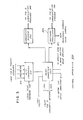
- a lubrication passage 139 is disposed through bearing cap 132 to carry an oil-air lubrication mist mixture to bearings 124a and 124b from a lubrication system 230 illustrated in Fig. 3, which is configured identically to lubrication system 22 described in our copending European patent application No.
- a temperature sensor 140 (best illustrated in Fig. 2) is disposed in bearing cap 132 adjacent to bearing 124a and supplies A/D converter 218 illustrated in Fig. 5 with a signal varying in accordance with bearing temperature.
- micro- computer 220 Fig.
- microcomputer 220 (Fig. 5) utilizes the output signals from each of thrust sensor pairs 137a and 137b to sense variations in radial and axial thrust, respectively, which in practice, precedes changes in spindle bearing temperature. By anticipating changes in spindle bearing temperature prior to their occurrence, microcomputer 220 is better able to regulate spindle bearing lubrication.
- Spindle 110 has a pair of tool gripping collets 140a and 140b, which are each integrated to a separate one of the spindle ends, respectively.
- Each of tool gripping collets 140a and 140b, respectively, is urged radially inward to grip shank 112 of the cutting tool by a separate one of collet nuts 142a and 142b which are each in threaded engagement with spindle 110 adjacent to a separate one of collets 140a and 140b.
- the spindle carries a pair of hollow bore collet nut drivers 145a and 145b, the collet nut drivers each being carried on the spindle adjacent to a separate one of the spindle ends so as to be coaxial with, and adjacent to, a separate one of collet nuts 142a and 142b, respectively.
- the bore through each collet nut driver is dimensioned to receive a respective one of the collet nuts.
- each collet nut driver such as collet nut driver 145a, for example, carries a set of splines 146a, which splines are complementary to the exterior splines 146b carried on the rearward end of each of the collet nuts, such as collet nut 142a, and are complementary to the exterior splines 146c carried on each end of spindle 110 adjacent to a separate one of collets 140a and 140b.
- Each collet nut driver such as collet nut driver 145a is slidable along the spindle between a first or inward most position at which location the collet nut driver is adjacent to an associated one of bearing caps 132 and 160, respectively, and a second or outward most position at which location the collet nut driver is distal from the corresponding bearing cap.
- the collet nut driver is displaced along the spindle to its first or inward most position adjacent to its corresponding bearing cap, the splines on the interior surface of the collet nut driver engage the exterior splines on both the collet nut and the spindle, thus preventing the collet nut from rotating independently of the spindle.
- Each collet nut driver is restrained from axial movement, once slidably moved to its inward most position to engage both the spindle splines and the splines on the corresponding collet nut, by a pair of Vlier screws 148, only one of which is shown, the Vlier screws being threaded into the spindle to extend radially therefrom so that each engages a circumferential groove circumscribing the inner bore of a corresponding collet nut driver.
- Proximity switches 150a and 150b are each mounted in a separate one of front and rear bearing caps 132 and 160, respectively, so that each switch is adjacent to a separate one of front and rear collet nut drivers 145a and 145b, respectively.
- Each of proximity switches 150a and 150b, respectively, is actuated when a separate one of collet nut drivers 145a and 145b, respectively, is slidably moved inwardly to be adjacent to a separate one of bearing caps 132 and 160, respectively, to jointly engage a separate one of collet nuts 142a and 142b, respectively, with the spindle.
- each proximity switch supplies microcomputer 220 with a signal indicative of the engagement of the corresponding collet nut and the spindle.
- microcomputer 220 supplies an inhibit signal to the drive amplifier controlling motor 114 to prevent spindle rotation. In this manner, damage to the cutting tool as well as the machine tool operator is prevented when the cutting tool is not firmly held in the spindle.
Description
- The present invention concerns a control system for machine tools or the like, to regulate spindle bearing preload to assure optimum . machine tool performance.
- It is known from document US-A-3 687 511 to adjust automatically the clearance or play in an antifriction bearing for a machine tool spindle. In this document sensors detect the distance between the bearing housing and the spindle shaft and adjust the bearing preload by movement of the bearing housing to and fro on a tapered needle or roller bearing. The aim of the arrangement is to keep the play in the bearing constant over a wide range of speeds and loads.
- The present invention provides an apparatus for rotatably supporting a member journaled in a frame by antifriction bearings; sensing means in position for determining the axial and/or radial thrust imposed in use upon said rotatable member and to produce a signal representing the thrust; pressure means disposed in use to apply a force to said bearings for preloading the bearings; adjusting means connected to regulate said pressure means for varying the force on said bearings; a control means connected to receive the signal from said sensing means representing the thrust on the rotatable member; and means connecting said control means to said adjusting means for regulating the operation of said adjusting means in accordance with the signal received from said sensing means so that the preload force applied to said bearings is continually adjusted according to a predetermined relationship to suit the prevailing conditions.
- In the drawings:
- Fig. 1 is a side elevational view of a high speed machine tool spindle of a machine tool;
- Fig. 2 is an enlarged view of a portion of the high speed spindle illustrated in Fig. 1; and
- Fig. 3 is a block diagram of a modification of the control apparatus of Fig. 1 for controlling a machine tool embodying the spindle of Figs. 1 and 2.
- Figs. 1 and 2 illustrate a portion of a high
speed spindle assembly 100 of a numerically controlled machine tool.Spindle assembly 100 is typically disposed in a frame such as the machine tool spindlehead (not shown) which is linearly movable on the machine tool along an axis at a rate referred to as the spindle axis feedrate.Spindle assembly 100 comprises aspindle 110 having an axially extending bore therethrough dimensioned to receive theshank 112 of a cutting tool therein. Spindle 110 is integral with the shaft of amotor 114 comprised of a stator 114a and a rotor 114b. Akey 115 extending fromspindle 110 engages a complementary keyway in the rotor (not shown) to lock the spindle to the rotor so thatspindle 110 rotates co-jointly with rotor 114b. - Spindle 110 extends through the
case 116 ofmotor 114 and is journalled to the front and rear ofmotor case 116 by front andrear spindle bearings spindle 110 adjacent to a separate one of the ends thereof. Front spindle bearing 118 comprises a pair ofball bearings 124a and 124b, respectively, which are carried onspindle 110 between a shoulder or flange 126 andthreads 127. Anut 128 engagesthreads 127 to urge the lower races ofball bearings 124a and 124b against shoulder 126. Adjusting the displacement ofnut 128 from shoulder 126 serves to vary the force against, or the preloading on, the lower ball bearing races. The upper races ofball bearings 124a and 124b are urged against a vertical wall inmotor case 116 by anannular ring piston 129 which is reciprocally disposed in apiston chamber 130 within a front bearingcap 132 fastened tomotor case 116 bybolts 134 which are disposed through passages spaced equidistantly about the bearing cap circumference. - The amount of force or preloading on the upper races of
ball bearings 124a and 124b varies in accordance with the pressure of hydraulic fluid admitted intopiston chamber 130 through a connectingpassage 136 from a source of hydraulic fluid (not shown) which is coupled to connectingpassage 136 through a pressure regulator (described hereinafter). The pressure of hydraulic fluid admitted through connectingpassage 136 from the source of hydraulic fluid is varied by the pressure regulator in accordance with radial and axial spindle bearing thrust. To this end, two pairs ofspindle thrust sensors 137a and 137b, respectively, whose sensors are typically comprised of a magnetic or capacitive transducer, are disposed within bearingcap 132 adjacent to spindle shoulder 126 to measure radial and axial spindle thrust, respectively. Referring now to Fig. 2 which is an enlarged fragmentary view of a portion of the spindle assembly illustrated in Fig. 1, to measure radial spindle thrust, one thrust sensor ofthrust sensor pair 137a is vertically disposed inbearing cap 132 adjacent to flange 126 above the axis 138 ofspindle 110; the other thrust sensor (not shown) ofthrust sensor pair 137a is vertically disposed inbearing cap 132 so as to be adjacent to flange 126 below the spindle axis. To measure axial bearing thrust, one thrust sensor of thrust sensor pair 137b is horizontally mounted inbearing cap 132 adjacent to the flange so as to be above the spindle axis while the other thrust sensor (not shown) of thrust sensor pair 137b is horizontally mounted in the bearing cap adjacent to flange 126 below spindle axis 138. The thrust sensors ofthrust sensor pairs 137a and 137b are connected differentially to produce a signal varying in accordance with radial and axial spindle thrust, respectively. - The output signal produced by each of
thrust sensor pairs 137a and 137b, which varies in accordance with radial and axial spindle thrust, respectively, is supplied to a control apparatus 200 illustrated in Fig. 5 which controls the spindle axis rate and bearing preload as well as the percentage volume of oil in the oil-air lubrication mist mixture. Control apparatus 200 comprises an analog to digital (A/D)converter 218, for converting the analog signal from each ofthrust sensor pairs 137a and 137b (Figs. 1 and 2) into a digital signal which is transmitted to a micro-computer 220. Micro-computer 220 is responsive to the output signals from A/D converter 218 and, during intervals when the radial and axial thrusts on spindle 110 (Fig. 1) are large, as will likely occur when spindle speeds are low and the force on the cutting tool is disposed within the spindle is large,microcomputer 220 modulates the output signal supplied to apressure regulator 225, coupled between the source of pressurized hydraulic fluid and passage 136 (Fig. 1) to increase the pressure of hydraulic fluid admitted through connectingpassage 136 to piston chamber 130 (Fig. 1) so as to increase the force ofpiston 130 against the upper races ofbearings 124a and 124b (Fig. 1), accordingly, thereby increasing bearing preload to reduce bearing chatter. In addition, during intervals of large radial and axial spindle thrusts,microcomputer 220 also supplies an output signal to the spindle-head axis drive motor amplifier (not shown) to reduce the axis feedrate accordingly. At high spindle speeds when the force on the cutting tool held in spindle 110 (Fig. 1) is likely to be much lower, thereby resulting in lower radial and axial thrusts on spindle 110 (Fig. 1)microcomputer 220, in responsecommands pressure regulator 225 to reduce the pressure of fluid admitted intopiston chamber 130 through connectingpassage 136, thereby reducing the preload onbearing 124a and 124b (Figs. 1 and 2). During this same interval of lower radial and axial spindle bearing thrusts,microcomputer 220 also supplies an output signal to the spindlehead axis drive system motor amplifier to command an increase in the spindle feedrate accordingly. In this way,microcomputer 220 dynamically regulates the preloading onspindle bearings 124a and 124b. - In addition to being responsive to radial and axial spindle thrust,
microcomputer 220 is also responsive to machine tool spindle speed, as sensed by a tachometer, or as determined by the machine tool control system. During intervals when machine tool spindle speed is increased, it may be desirable to decrease bearing preload. This is readily accomplished bymicrocomputer 220 in response to an increase in magnitude of the speed signal supplied thereto. Conversely, when spindle speed decreases,microcomputer 220 increases the volume of fluid admitted by the pressure regulated into piston chamber 130 (Fig. 2) through connecting passage 136 (Fig. 2) to increase bearing preload. - Referring back to Figs. 1 and 2 jointly, a
lubrication passage 139 is disposed through bearingcap 132 to carry an oil-air lubrication mist mixture tobearings 124a and 124b from alubrication system 230 illustrated in Fig. 3, which is configured identically to lubrication system 22 described in our copending European patent application No. A temperature sensor 140 (best illustrated in Fig. 2) is disposed inbearing cap 132 adjacent to bearing 124a and supplies A/D converter 218 illustrated in Fig. 5 with a signal varying in accordance with bearing temperature. In accordance with the digital output signal from A/D converter 218, micro- computer 220 (Fig. 3) while regulating bearing preload and the spindle axis feedrate, also supplies a pair of control signals tolubrication system 230 to regulate the percentage volume of oil in the oil-air mist mixture supplied throughlubrication passage 139 tobearings 124a and 124b. To provide for faster lubrication system response, microcomputer 220 (Fig. 5) utilizes the output signals from each ofthrust sensor pairs 137a and 137b to sense variations in radial and axial thrust, respectively, which in practice, precedes changes in spindle bearing temperature. By anticipating changes in spindle bearing temperature prior to their occurrence,microcomputer 220 is better able to regulate spindle bearing lubrication. - Spindle 110 has a pair of
tool gripping collets 140a and 140b, which are each integrated to a separate one of the spindle ends, respectively. Each oftool gripping collets 140a and 140b, respectively, is urged radially inward togrip shank 112 of the cutting tool by a separate one of collet nuts 142a and 142b which are each in threaded engagement withspindle 110 adjacent to a separate one ofcollets 140a and 140b. To prevent the collet nut at each end of the spindle from loosening during high speed rotation ofspindle 110, the spindle carries a pair of hollow bore collet nut drivers 145a and 145b, the collet nut drivers each being carried on the spindle adjacent to a separate one of the spindle ends so as to be coaxial with, and adjacent to, a separate one of collet nuts 142a and 142b, respectively. The bore through each collet nut driver is dimensioned to receive a respective one of the collet nuts. The interior surface of the bore through each collet nut driver, such as collet nut driver 145a, for example, carries a set of splines 146a, which splines are complementary to the exterior splines 146b carried on the rearward end of each of the collet nuts, such as collet nut 142a, and are complementary to the exterior splines 146c carried on each end ofspindle 110 adjacent to a separate one ofcollets 140a and 140b. Each collet nut driver, such as collet nut driver 145a is slidable along the spindle between a first or inward most position at which location the collet nut driver is adjacent to an associated one ofbearing caps screws 148, only one of which is shown, the Vlier screws being threaded into the spindle to extend radially therefrom so that each engages a circumferential groove circumscribing the inner bore of a corresponding collet nut driver. -
Proximity switches rear bearing caps proximity switches bearing caps microcomputer 220 with a signal indicative of the engagement of the corresponding collet nut and the spindle. Should one of collet nut drivers 145a and 145b be slidably moved outwardly causing a corresponding one ofproximity switches microcomputer 220 supplies an inhibit signal to the driveamplifier controlling motor 114 to prevent spindle rotation. In this manner, damage to the cutting tool as well as the machine tool operator is prevented when the cutting tool is not firmly held in the spindle.
Claims (5)
Applications Claiming Priority (2)
| Application Number | Priority Date | Filing Date | Title |
|---|---|---|---|
| US316059 | 1981-10-29 | ||
| US06/316,059 US4527661A (en) | 1981-10-29 | 1981-10-29 | Adaptive control system for machine tool or the like |
Publications (3)
| Publication Number | Publication Date |
|---|---|
| EP0078421A2 EP0078421A2 (en) | 1983-05-11 |
| EP0078421A3 EP0078421A3 (en) | 1983-08-03 |
| EP0078421B1 true EP0078421B1 (en) | 1987-12-23 |
Family
ID=23227295
Family Applications (2)
| Application Number | Title | Priority Date | Filing Date |
|---|---|---|---|
| EP82109473A Expired EP0078420B1 (en) | 1981-10-29 | 1982-10-13 | Lubrication system for machine tool or the like |
| EP82109474A Expired EP0078421B1 (en) | 1981-10-29 | 1982-10-13 | Adaptive control system for machine tool or the like |
Family Applications Before (1)
| Application Number | Title | Priority Date | Filing Date |
|---|---|---|---|
| EP82109473A Expired EP0078420B1 (en) | 1981-10-29 | 1982-10-13 | Lubrication system for machine tool or the like |
Country Status (8)
| Country | Link |
|---|---|
| US (1) | US4527661A (en) |
| EP (2) | EP0078420B1 (en) |
| JP (2) | JPS5884294A (en) |
| KR (1) | KR860000747B1 (en) |
| CA (2) | CA1186775A (en) |
| DE (2) | DE3277863D1 (en) |
| IL (1) | IL66654A0 (en) |
| NO (2) | NO823223L (en) |
Families Citing this family (75)
| Publication number | Priority date | Publication date | Assignee | Title |
|---|---|---|---|---|
| JPS6188015A (en) * | 1984-10-08 | 1986-05-06 | Nippon Seiko Kk | Pre-load controlling spindle unit |
| JPS61127922A (en) * | 1984-11-27 | 1986-06-16 | Okuma Mach Works Ltd | Automatic preload regulating method for rolling bearing and device thereof |
| DE3523254A1 (en) * | 1985-06-28 | 1987-01-02 | Brueckner Trockentechnik Gmbh | METHOD AND DEVICE FOR THE AUTOMATIC LUBRICATION OF THE CHAIN LINKS OF AN ENDLESS CONTINUOUS RAILWAY TRANSPORT CHAIN IN A TENSING MACHINE |
| JPS62130218U (en) * | 1986-02-07 | 1987-08-17 | ||
| NL8601665A (en) * | 1986-06-25 | 1988-01-18 | Skf Ind Trading & Dev | DEVICE FOR SUPPLYING A LUBRICANT TO A MECHANISM, IN PARTICULAR A ROLL BEARING. |
| DE3637776A1 (en) * | 1986-11-06 | 1988-05-11 | Kloeckner Humboldt Deutz Ag | LUBRICATION SYSTEM FOR A GAS TURBINE ENGINE |
| JPS63146365U (en) * | 1987-03-13 | 1988-09-27 | ||
| JP2516382B2 (en) * | 1987-11-06 | 1996-07-24 | セイコー精機株式会社 | Machining equipment with magnetic bearing as main shaft |
| JPS6449795A (en) * | 1987-08-18 | 1989-02-27 | Takano Corp | Lubrication monitor for machine |
| US4911267A (en) * | 1987-08-31 | 1990-03-27 | Yohwa Trading Co., Ltd. | Oiler with drippage preventing device |
| DE3838786A1 (en) * | 1988-02-16 | 1989-08-24 | Werkzeugmasch Heckert Veb | Method and device for the controlled lubrication of pairs of friction locations |
| DE3823497A1 (en) * | 1988-07-11 | 1990-01-18 | Siemens Ag | PIEZOELECTRIC LUBRICATION DEVICE FOR A BEARING |
| JP2765897B2 (en) * | 1988-12-23 | 1998-06-18 | 株式会社日立製作所 | Lubricant supply method and bearing device using the method |
| FR2642877A1 (en) * | 1989-02-07 | 1990-08-10 | Francon Henri | Method of processing documentation by optical reading |
| DE3904952C1 (en) * | 1989-02-16 | 1990-07-26 | Willy Vogel Ag, 1000 Berlin, De | |
| US5224051A (en) * | 1989-05-19 | 1993-06-29 | Cincinnati Milacron, Inc. | Fluid condition monitoring and controlling system for a metalworking fluid central system |
| FR2647182B1 (en) * | 1989-05-22 | 1992-01-10 | Cit Alcatel | DEVICE FOR THE GREASE SUPPLY OF MULTIPLE BEARINGS |
| US5125480B1 (en) * | 1990-12-10 | 1995-04-04 | Lubrication Syst Co Texas Inc | Lubrication system |
| DE4203994A1 (en) * | 1992-02-12 | 1993-08-19 | Hermle Berthold Maschf Ag | MACHINE TOOL WITH AN AUTOMATIC THERMAL EXPANSION COMPENSATION DEVICE |
| US5318152A (en) | 1993-01-29 | 1994-06-07 | Lubrication Systems Company Of Texas, Inc. | Lubricating system |
| CN1059023C (en) * | 1993-03-18 | 2000-11-29 | 巴马格股份公司 | Antifriction bearing |
| FR2720308B1 (en) * | 1994-05-31 | 1996-08-09 | Recoules Fils Ets | Pneumatic machining machine. |
| US5816122A (en) * | 1996-04-30 | 1998-10-06 | General Dynamics Advanced Technology Systems, Inc. | Apparatus and method for adaptive suppression of vibrations in mechanical systems |
| US7017712B1 (en) * | 1997-03-19 | 2006-03-28 | Trico Mfg. Corp. | Apparatus and method for lubricant condition control and monitoring |
| DE19722970C2 (en) * | 1997-05-31 | 1999-04-15 | Rebs Zentralschmiertech Gmbh | Device for distributing a lubricant-air mixture to different lubrication channels of the machine housing |
| JPH10339326A (en) * | 1997-06-06 | 1998-12-22 | Nippon Seiko Kk | Rolling bearing for hard disk drive |
| DE19748649C2 (en) * | 1997-11-04 | 2000-05-25 | Karlsruhe Forschzent | Device for lubricating moving components |
| US6167318A (en) * | 1997-12-22 | 2000-12-26 | Alemite Corporation | Oil mist generating system and method |
| JPH11287395A (en) * | 1997-12-23 | 1999-10-19 | Satzinger Gmbh & Co | Lubricant supplying method for device having many place to be lubricated and centralized lubricating equipment for executing method |
| US5948968A (en) * | 1998-06-22 | 1999-09-07 | Lubrication Systems Company Of Texas, Inc. | Oil mist gauge |
| US6477885B1 (en) * | 1998-12-25 | 2002-11-12 | Nsk Ltd. | Lubricant applying system for a rolling bearing |
| US6312226B1 (en) | 1999-03-16 | 2001-11-06 | Roy F. Senior, Jr. | Device and method for detecting bearing overheating in turbine pump systems |
| NL1014210C2 (en) * | 2000-01-27 | 2001-07-30 | Skf Eng & Res Centre Bv | Intelligent bearing maintenance. |
| DE10015996C2 (en) * | 2000-03-31 | 2002-11-07 | Spirka Maschb Gmbh | Method for operating a rotor braiding machine and rotor braiding machine |
| FR2816692B1 (en) * | 2000-11-15 | 2003-01-03 | Vogel Mecafluid | LUBRICATION AND MONITORING SYSTEM FOR A LUBRICATED ELEMENT |
| JP2003042392A (en) * | 2001-07-27 | 2003-02-13 | I M N Kk | Lubricating oil supply method in rotating part supporting body |
| ITMI20030676A1 (en) * | 2003-04-07 | 2004-10-08 | Auges S R L | DEVICE AND METHOD TO DELIVER A LUBRICANT AND / OR REFRIGERANT FLUID IN MECHANICAL PROCESSING |
| JP4151472B2 (en) * | 2003-04-25 | 2008-09-17 | 株式会社ジェイテクト | Roller bearing device and lubrication method for roller bearing |
| DE10336765A1 (en) | 2003-08-08 | 2005-03-24 | Contitech Elastomer-Beschichtungen Gmbh | Blanket and method for its production |
| WO2006029063A2 (en) * | 2004-09-07 | 2006-03-16 | Unist, Inc. | Machine lubricant and coolant distribution system |
| US20060073303A1 (en) * | 2004-10-04 | 2006-04-06 | Trico Mfg. Corp. | Flinger disc |
| US7862875B2 (en) * | 2004-10-04 | 2011-01-04 | Trico Corporation | Flinger disc |
| JP4424293B2 (en) * | 2005-09-29 | 2010-03-03 | 株式会社ジェイテクト | Rolling bearing device |
| DE102006059838B3 (en) * | 2006-12-15 | 2008-04-03 | Rebs Zentralschmiertechnik Gmbh | Lubricant supply for roller bearing for rolling mill has detector for detecting temperature of gas flowing out of bearing that outputs warning signal if difference between detected and reference temperature exceeds maximum permissible value |
| DE102007013611A1 (en) | 2007-03-22 | 2008-09-25 | Contitech Elastomer-Beschichtungen Gmbh | Blanket with a non-stretchable carrier layer |
| DE102007021294B4 (en) * | 2007-05-07 | 2009-10-01 | P & L Gmbh & Co. Kg | Dynamically optimized machine tool with superimposed drive systems |
| JP2009061571A (en) * | 2007-09-10 | 2009-03-26 | Ntn Corp | Spindle device for machine tool spindle |
| BE1017806A3 (en) * | 2007-10-08 | 2009-07-07 | Ct Rech Metallurgiques Asbl | ATOMIZATION LUBRICATION SYSTEM AND METHOD FOR ROLLING CYLINDERS. |
| SE531604C2 (en) * | 2007-10-17 | 2009-06-02 | Atlas Copco Rock Drills Ab | Device and method for controlling the supply of lubricant in a work vehicle |
| US8096164B2 (en) | 2008-01-17 | 2012-01-17 | Trico Corporation | Apparatus and methods for management of fluid condition |
| US8220671B2 (en) | 2008-03-12 | 2012-07-17 | Trico Corporation | Lubricant dispenser with nozzle |
| USD687923S1 (en) | 2008-06-03 | 2013-08-13 | Trico Corporation | Lubricant dispensing nozzle |
| DE102008052490A1 (en) * | 2008-10-21 | 2010-04-22 | Metso Lindemann Gmbh | Arrangement for the axial support of a shaft of a working machine |
| US8147684B2 (en) * | 2009-03-27 | 2012-04-03 | Trico Corporation | Apparatus and methods for lubricant filtration and drum pump filtration system |
| EP2488614A4 (en) * | 2009-10-16 | 2015-10-21 | Univ Virginia Patent Found | Gas-expanded lubricants for increased energy efficiency and related method and system |
| US8147683B2 (en) | 2010-01-22 | 2012-04-03 | Trico Corporation | Portable lubricant filtration system and method |
| CN103080628B (en) * | 2010-04-01 | 2016-03-30 | Skf公司 | The lubrication system improved |
| CN101972949A (en) * | 2010-10-27 | 2011-02-16 | 威海华东数控股份有限公司 | Screw lubrication detecting device for numerical control machine tool |
| WO2012109320A1 (en) * | 2011-02-08 | 2012-08-16 | The University Of Utah Research Foundation | System and method for dispensing a minimum quantity of cutting fluid |
| DE102011102539A1 (en) * | 2011-05-26 | 2012-11-29 | Linde Aktiengesellschaft | Aerosol lubricator, lubrication assembly and lubrication method |
| USD687922S1 (en) | 2012-04-25 | 2013-08-13 | Trico Corporation | Lubricant dispenser |
| USD687921S1 (en) | 2012-04-25 | 2013-08-13 | Trico Corporation | Lubricant dispenser |
| USD696956S1 (en) | 2012-04-25 | 2014-01-07 | Trico Corporation | Lubricant dispenser |
| DE102013100988A1 (en) | 2013-01-31 | 2014-07-31 | Baier & Köppel GmbH & Co. | Device for performing to state-dependant lubrication of sliding and/or rolling mating, has control units that are controlled by feeding units, such that lubricant and/or lubricant additive of sliding and/or rolling matings are supplied |
| DE102013114510A1 (en) * | 2013-12-19 | 2015-06-25 | Gea Mechanical Equipment Gmbh | Bearing arrangement for centrifuges |
| DE102015005634A1 (en) * | 2015-05-05 | 2015-08-06 | Bielomatik Leuze Gmbh & Co. Kg | Apparatus for minimal quantity lubrication |
| TWI564500B (en) * | 2015-05-22 | 2017-01-01 | 普陽商貿有限公司 | Intelligent oil-gas mixing lubrication system |
| US10576596B2 (en) * | 2015-10-22 | 2020-03-03 | Unist, Inc. | Minimum quantity lubrication system |
| JP6407905B2 (en) * | 2016-03-11 | 2018-10-17 | ファナック株式会社 | Main shaft bearing protection device and machine tool equipped with the same |
| KR101824580B1 (en) * | 2016-08-26 | 2018-02-01 | 하이윈 테크놀로지스 코포레이션 | Lubrication detection method for linear motion system |
| CN108608016A (en) * | 2018-04-27 | 2018-10-02 | 北京科技大学 | A kind of discrimination method and its system of electro spindle rapid warm raising |
| DE102018111083A1 (en) * | 2018-05-08 | 2019-11-14 | Broetje-Automation Gmbh | Atomizer unit of a minimal quantity lubrication system |
| WO2020026196A1 (en) | 2018-08-02 | 2020-02-06 | Unist, Inc. | Minimum quantity lubrication system and method |
| EP4000740A1 (en) | 2020-11-19 | 2022-05-25 | Alfa Laval Corporate AB | A method of greasing a decanter centrifuge |
| CN115289377A (en) * | 2022-07-14 | 2022-11-04 | 清华大学 | Oil-gas two-phase supply system and method with adjustable oil-gas ratio wide range |
Citations (1)
| Publication number | Priority date | Publication date | Assignee | Title |
|---|---|---|---|---|
| US3687511A (en) * | 1970-01-23 | 1972-08-29 | Werkzeug Mas Fab Adolf Waldric | Device for infinitely variable adjustment of the play of an antifriction bearing for a spindle or the like |
Family Cites Families (40)
| Publication number | Priority date | Publication date | Assignee | Title |
|---|---|---|---|---|
| US3066578A (en) * | 1958-12-17 | 1962-12-04 | Cincinnati Milling Machine Co | Temperature control of machine tool |
| FR1223607A (en) * | 1959-01-31 | 1960-06-17 | Device intended to prevent local expansions in machine parts in which high capacity tool spindles rotate | |
| US3027625A (en) * | 1959-05-01 | 1962-04-03 | Curtiss Wright Corp | Mist coolant system |
| US3071207A (en) * | 1960-08-25 | 1963-01-01 | Gen Electric | Lubrication system for high temperature environments |
| DE1196906B (en) * | 1962-11-21 | 1965-07-15 | Kugelfischer G Schaefer & Co | Device for measuring the clearance in radial roller bearings |
| GB1020250A (en) * | 1963-07-16 | 1966-02-16 | Toyoda Machine Works Ltd | Means for controlling pre-load applied to a shaft bearing |
| US3211060A (en) * | 1963-12-11 | 1965-10-12 | Giddings & Lewis | Spindle bearing preload assembly |
| US3222991A (en) * | 1964-05-22 | 1965-12-14 | Cincinnati Milling Machine Co | Bearing preload mechanism for machine tool |
| GB1013139A (en) | 1964-09-04 | 1965-12-15 | Rolls Royce | Gas turbine engine |
| GB1205487A (en) * | 1968-03-30 | 1970-09-16 | Ferranti Ltd | Improvements relating to bearing systems |
| US3555962A (en) * | 1968-06-03 | 1971-01-19 | New Britain Machine Co | Machine tool |
| US3487467A (en) * | 1968-07-08 | 1969-12-30 | Eaton Yale & Towne | Thermal electric bearing monitoring system |
| US3625308A (en) * | 1969-08-21 | 1971-12-07 | Litton Industries Inc | Spindle lubrication safety device |
| US3579073A (en) * | 1970-05-20 | 1971-05-18 | Richard Johnstone | Spindle growth compensator |
| DE2025693A1 (en) * | 1970-05-21 | 1971-12-09 | Siemens Ag | Procedure for monitoring the operating condition of rolling bearings |
| US3674112A (en) * | 1970-06-30 | 1972-07-04 | Houdaille Industries Inc | Centralized lubrication system |
| FR2106905A6 (en) * | 1970-09-29 | 1972-05-05 | Stephanois Rech | |
| BE787637A (en) * | 1971-12-20 | 1973-02-19 | Timken Co | BEARING STRUCTURE |
| JPS4895027U (en) * | 1972-02-15 | 1973-11-13 | ||
| DE2222279C3 (en) * | 1972-05-06 | 1982-02-11 | Karl H. Ing.(grad.) 7300 Esslingen Kessler | Device for continuously influencing the working temperature of a sewing needle in a sewing machine |
| DE2229990A1 (en) * | 1972-06-20 | 1974-01-10 | Walter Dr Ing Klaschka | LUBRICATION SYSTEM |
| US3792434A (en) * | 1972-07-14 | 1974-02-12 | J Williams | Bearing temperature sensing apparatus for use on a trailer |
| US3856114A (en) * | 1973-01-29 | 1974-12-24 | Kearney & Trecker Corp | Automatic lubrication system |
| FR2239150A5 (en) * | 1973-07-26 | 1975-02-21 | Cit Alcatel | Cooling system for roller bearing - has helical groove for cooling fluid in the fixed race |
| CH579742A5 (en) * | 1974-09-11 | 1976-09-15 | Voumard Machines Co Sa | |
| FR2326270A1 (en) * | 1975-10-02 | 1977-04-29 | Europ Propulsion | TOOL HOLDER SPINDLE ASSEMBLY, ESPECIALLY FOR GRINDING MACHINE |
| US4133484A (en) * | 1976-06-07 | 1979-01-09 | Joseph Jannone | Apparatus for spraying liquids in mono-dispersed form with capacity to control the quantity of spray |
| US4122720A (en) * | 1977-04-07 | 1978-10-31 | Alnor Instrument Company | Diesel engine exhaust temperature monitor |
| CH620253A5 (en) * | 1977-04-14 | 1980-11-14 | Sulzer Ag | |
| US4272216A (en) * | 1978-12-20 | 1981-06-09 | Kearney & Trecker Corporation | Machine tool lubrication system |
| US4198676A (en) * | 1978-12-20 | 1980-04-15 | Livezey Robert L Jr | General purpose electronic thermometer having selective data recovery, data conversion, and data derivation capabilities |
| US4284174A (en) * | 1979-04-18 | 1981-08-18 | Avco Corporation | Emergency oil/mist system |
| US4312424A (en) * | 1979-07-18 | 1982-01-26 | Washington Irrigation & Development Company | Automatic grease lubrication system for metering and dispensing lubrication grease onto rolling-sliding, line contact, bearing surface surface |
| US4326603A (en) * | 1979-12-17 | 1982-04-27 | International Business Machines Corporation | Lubrication control apparatus |
| DE3007512C2 (en) * | 1980-02-28 | 1982-04-29 | Fa. Hermann Heye, 3063 Obernkirchen | Device for applying a lubricating or separating liquid to a glass molding machine part |
| DE3016136A1 (en) * | 1980-04-24 | 1981-10-29 | Gerhard Dr.-Ing. Lechler | Thermal stabiliser for machine tool spindles - has gaseous or lubricating coolant, or thermal medium and has temp. sensor for spindle bearing or housing |
| US4368803A (en) * | 1980-08-07 | 1983-01-18 | Madison-Kipp Corporation | Apparatus for dispensing fluid onto a moving mechanical system |
| JPS5765495A (en) * | 1980-10-06 | 1982-04-21 | Toshiba Corp | Bearing lubricator |
| US4403296A (en) * | 1980-12-18 | 1983-09-06 | Electromedics, Inc. | Measuring and determination device for calculating an output determination based on a mathematical relationship between multiple different input responsive transducers |
| US4445168A (en) * | 1981-06-24 | 1984-04-24 | Houdaille Industries, Inc. | Apparatus and method for micro-computer control of lubrication system |
-
1981
- 1981-10-29 US US06/316,059 patent/US4527661A/en not_active Expired - Lifetime
-
1982
- 1982-08-26 IL IL66654A patent/IL66654A0/en unknown
- 1982-09-23 NO NO823223A patent/NO823223L/en unknown
- 1982-09-23 NO NO823224A patent/NO823224L/en unknown
- 1982-10-13 DE DE8282109474T patent/DE3277863D1/en not_active Expired
- 1982-10-13 EP EP82109473A patent/EP0078420B1/en not_active Expired
- 1982-10-13 DE DE8282109473T patent/DE3271418D1/en not_active Expired
- 1982-10-13 EP EP82109474A patent/EP0078421B1/en not_active Expired
- 1982-10-28 CA CA000414360A patent/CA1186775A/en not_active Expired
- 1982-10-28 CA CA000414359A patent/CA1197594A/en not_active Expired
- 1982-10-28 JP JP57189969A patent/JPS5884294A/en active Granted
- 1982-10-28 JP JP57189968A patent/JPS5882640A/en active Granted
- 1982-10-29 KR KR8204880A patent/KR860000747B1/en active
Patent Citations (1)
| Publication number | Priority date | Publication date | Assignee | Title |
|---|---|---|---|---|
| US3687511A (en) * | 1970-01-23 | 1972-08-29 | Werkzeug Mas Fab Adolf Waldric | Device for infinitely variable adjustment of the play of an antifriction bearing for a spindle or the like |
Also Published As
| Publication number | Publication date |
|---|---|
| EP0078421A3 (en) | 1983-08-03 |
| EP0078420A3 (en) | 1983-06-08 |
| CA1197594A (en) | 1985-12-03 |
| IL66654A0 (en) | 1982-12-31 |
| EP0078420A2 (en) | 1983-05-11 |
| JPS6158241B2 (en) | 1986-12-10 |
| CA1186775A (en) | 1985-05-07 |
| JPS6229675B2 (en) | 1987-06-27 |
| JPS5882640A (en) | 1983-05-18 |
| EP0078420B1 (en) | 1986-05-28 |
| NO823224L (en) | 1983-05-02 |
| NO823223L (en) | 1983-05-02 |
| DE3277863D1 (en) | 1988-02-04 |
| DE3271418D1 (en) | 1986-07-03 |
| US4527661A (en) | 1985-07-09 |
| KR860000747B1 (en) | 1986-06-18 |
| EP0078421A2 (en) | 1983-05-11 |
| JPS5884294A (en) | 1983-05-20 |
Similar Documents
| Publication | Publication Date | Title |
|---|---|---|
| EP0078421B1 (en) | Adaptive control system for machine tool or the like | |
| US4514123A (en) | Adaptive control system for machine tool or the like | |
| US4657412A (en) | Variable preload bearing assembly | |
| EP0997657B1 (en) | Adjustable preload spindle | |
| US6565293B2 (en) | Pneumatic machine tool | |
| EP0169034A2 (en) | Mechanism for pre-loading bearings | |
| WO2011037140A1 (en) | Spindle device of machining center | |
| EP0962281A3 (en) | Industrial machine having abnormal vibration detecting function | |
| US4664571A (en) | Tool abnormality detector | |
| JPS6188015A (en) | Pre-load controlling spindle unit | |
| US4911588A (en) | Tapping apparatus | |
| EP0927088B1 (en) | An arrangement relating to high-speed tools | |
| KR860000762B1 (en) | Preloading control device of a bearing | |
| US4204442A (en) | Cutter holding device in a polygon cutting apparatus | |
| JPS646899B2 (en) | ||
| US6328509B1 (en) | Arrangement relating to high-speed tools | |
| JP3570688B2 (en) | Tool abnormality detection device | |
| US6318937B1 (en) | Arrangement relating to high-speed tools | |
| EP0920942B1 (en) | Hydraulic rotary cylinder | |
| RU1786302C (en) | Multioperation machine tool spindle assembly | |
| KR900008002Y1 (en) | Disc type center | |
| SU765539A1 (en) | Hydraulic-pressure bearing assembly | |
| JPS6250242B2 (en) | ||
| JPH05253716A (en) | Boring unit | |
| SU1212701A1 (en) | Spindle assembly of heavy-duty lathe |
Legal Events
| Date | Code | Title | Description |
|---|---|---|---|
| PUAI | Public reference made under article 153(3) epc to a published international application that has entered the european phase |
Free format text: ORIGINAL CODE: 0009012 |
|
| AK | Designated contracting states |
Designated state(s): BE CH DE FR GB IT LI |
|
| PUAL | Search report despatched |
Free format text: ORIGINAL CODE: 0009013 |
|
| AK | Designated contracting states |
Designated state(s): BE CH DE FR GB IT LI |
|
| 17P | Request for examination filed |
Effective date: 19840202 |
|
| GRAA | (expected) grant |
Free format text: ORIGINAL CODE: 0009210 |
|
| AK | Designated contracting states |
Kind code of ref document: B1 Designated state(s): BE CH DE FR GB IT LI |
|
| PG25 | Lapsed in a contracting state [announced via postgrant information from national office to epo] |
Ref country code: LI Effective date: 19871223 Ref country code: IT Free format text: LAPSE BECAUSE OF FAILURE TO SUBMIT A TRANSLATION OF THE DESCRIPTION OR TO PAY THE FEE WITHIN THE PRESCRIBED TIME-LIMIT;WARNING: LAPSES OF ITALIAN PATENTS WITH EFFECTIVE DATE BEFORE 2007 MAY HAVE OCCURRED AT ANY TIME BEFORE 2007. THE CORRECT EFFECTIVE DATE MAY BE DIFFERENT FROM THE ONE RECORDED. Effective date: 19871223 Ref country code: FR Free format text: THE PATENT HAS BEEN ANNULLED BY A DECISION OF A NATIONAL AUTHORITY Effective date: 19871223 Ref country code: CH Effective date: 19871223 Ref country code: BE Effective date: 19871223 |
|
| REF | Corresponds to: |
Ref document number: 3277863 Country of ref document: DE Date of ref document: 19880204 |
|
| REG | Reference to a national code |
Ref country code: CH Ref legal event code: PL |
|
| EN | Fr: translation not filed | ||
| PGFP | Annual fee paid to national office [announced via postgrant information from national office to epo] |
Ref country code: DE Payment date: 19881008 Year of fee payment: 7 |
|
| PG25 | Lapsed in a contracting state [announced via postgrant information from national office to epo] |
Ref country code: GB Effective date: 19881013 |
|
| PLBE | No opposition filed within time limit |
Free format text: ORIGINAL CODE: 0009261 |
|
| STAA | Information on the status of an ep patent application or granted ep patent |
Free format text: STATUS: NO OPPOSITION FILED WITHIN TIME LIMIT |
|
| 26N | No opposition filed | ||
| GBPC | Gb: european patent ceased through non-payment of renewal fee | ||
| PG25 | Lapsed in a contracting state [announced via postgrant information from national office to epo] |
Ref country code: DE Effective date: 19900703 |