EP0078083A2 - Verfahren und Platte zur Bearbeitung elektronischen Miniaturbauelemente - Google Patents
Verfahren und Platte zur Bearbeitung elektronischen Miniaturbauelemente Download PDFInfo
- Publication number
- EP0078083A2 EP0078083A2 EP82201316A EP82201316A EP0078083A2 EP 0078083 A2 EP0078083 A2 EP 0078083A2 EP 82201316 A EP82201316 A EP 82201316A EP 82201316 A EP82201316 A EP 82201316A EP 0078083 A2 EP0078083 A2 EP 0078083A2
- Authority
- EP
- European Patent Office
- Prior art keywords
- passageways
- parts
- cross
- passageway
- plate
- Prior art date
- Legal status (The legal status is an assumption and is not a legal conclusion. Google has not performed a legal analysis and makes no representation as to the accuracy of the status listed.)
- Granted
Links
Images


Classifications
-
- H—ELECTRICITY
- H01—ELECTRIC ELEMENTS
- H01G—CAPACITORS; CAPACITORS, RECTIFIERS, DETECTORS, SWITCHING DEVICES, LIGHT-SENSITIVE OR TEMPERATURE-SENSITIVE DEVICES OF THE ELECTROLYTIC TYPE
- H01G13/00—Apparatus specially adapted for manufacturing capacitors; Processes specially adapted for manufacturing capacitors not provided for in groups H01G4/00 - H01G11/00
- H01G13/006—Apparatus or processes for applying terminals
Definitions
- My invention relates to a method and a means for processing miniature capacitors or the like useful in aplying a conductive coating to the ends thereof.
- the claims of this application include a method of coating ends of miniature electronic parts and include a plate supporting a number of said miniature electronic parts.
- the purpose of the processing and equipment is to conduct certain operations on parts, especially to apply to the ends of a miniature electronic component 16, in sequence, coatings 34, 36.
- Figure 9 shows the part with coating 34 and Figure 14 shows the addition of coating 36.
- Part 16 could be a chip capacitor or a resistor for example. In size, an example would be around 1/16 x 1/16" in cross-section and 3/32 to 5/32 11 long but the part could be larger or smaller than that.
- a capacitor for example, has a sizable number of conductive layers separated by non-conductive layers. Conductive layers are interfingered as to electrical connection of layers to opposite ends of part 16. In any case, such miniature part 16 needs to have conductive coatings applied to opposite ends and my invention concerns that operation.
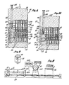
- Figure 1 includes, from top to bottom, a part handling plate 10, a part loading plate 12, and a part feeding body 14.
- Figure 2 adds schematically the funtions of vibration, vacuum and spring mount to the Figure 1 parts to load parts in plate 12.
- Figure 3 shows part loading plate 12 and part handling plate 10 with electronic components 16 in place in plate 12.
- Figure 4 shows part punching means 18 used (a) to transfer parts 16 from part loading plate 12 to part handling plate 10, (b) used to transfer parts 16 from one side of part handling plate 10, and used to unload parts 16 from part handling plate 10.
- Figure 5 shows a step in the sequence of operations involving part pushing means 18.
- a bank of pushers 24 is shown in the upper part of the view, and plates 10, 12, a part unloading plate 20, and part pushing base 22 are shown in the lower part of the view.
- Figure 6 is like Figure 5 but with the pushers 24 of part pushing means 18 in the process of pushing parts 16 out of part loading plate 12 and into part handing plate 10. The ends of parts 16 are exposed above the upper face of plate 10.
- FIG. 7 illustrates resilient gripping of parts.
- Parts 16 usually are right-rectangular (square or rectangular in cross-section) whereas passageways 26 are round and normally have a diameter less than the maximum cross-sectional dimension of parts 16.
- the walls of passagways 26 are resiliently coated to accommodate and grip parts 16.
- Figure 8 shows equipment for processing a part handling plate 10 having the ends of electronic components 16 exposed above its upper face.
- the equipment includes conveying means 28, part coating equipment 30, and part heating equipment 32, used to coat ends of parts 16 and to bake such coatings.
- Figure 9 shows coating 34 applied to a first end of a part 16.
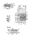
- Figure 10 is like Figure 6 but with part handling plate 10 inverted, after applying coating 34 and returning plate 10 to part pushing press 18. Parts 16 are being moved by pushers 24 into position exposing their second ends beyond the second face of plate 10, so that the second ends can be coated.
- Figure 11 shows plate 10 inverted from its Figure 10 position with the second ends of the parts 16 exposed, ready to run through the Figure 8 coating equipment.
- Figure 12 shows part pushing press 18 in the process of unloading parts from plate 10 into part unloading plate 20.
- Figure 13 shows parts 16 being dumped out of plate 20.
- Figure 14 shows part 16 with a coating 36 on its second end in addition to coating 34 on its first end.
- Parts 16 are continuously gripped by resilient walls in passageways 26 in plate 10 as they are moved to a first position exposing one end of parts 16 for coating and to a second position exposing the opposite end of parts 16 for coating and as they are unloaded.
- the resilient coating of the walls of passageways 26 extends from face to face of plate 10.
- part handling plate 10 has a multiplicity of part receiving passageways 26 having walls coated with resilient material.
- plate 10 is formed of metal with a recess 40 in each face extending throughout the major portions of the face to the marginal areas 42. This leaves a central web 44 of metal which has a multiplicity of bores 46.
- a resilient plastic material 48 is used to fill recesses 40 and bores 46 except for leaving part receiving passageways 26.
- Material 48 provides resilient walls for passageways 26, to receive and grip parts in the manner particularly illustrated in Figure 7.
- the material 48 can be selected from various applicable plastics or rubbers. An example is a pliable silicone rubber. Those skilled in the art will understand the selection of applicable materials and methods, tooling, etc., to form plate 10.
- material 48 is described as "resilient plastic” that term is defined to include plastics or natural or artificial rubbers which are suitable for the usage.
- the purpose of having recesses 40 is to better hold the plastics material 48 in place.
- Parts 16 usually will be square or rectangular in cross-section. Even if the parts 16 were circular in cross-section, the action of the walls of passageways 26 in gripping parts 16 would be similar. If the circular diameter of each passageway 26 is rectangular in cross-section a dimension of passageway 26 such as its width should be less than the corresponding minimum dimension of part 16 such as the width of a rectangular part in order to continuously resiliently grip part 16 in all positions in passageway 26 whether part 16 protrudes from an end passageway 26 or whether part 16 is centered or otherwise completely contained in passageway 26.
- the basic method of handling parts 16 in passageways 26 consists of (a) inserting the parts into the passageways, (b) moving the_parts so first ends are exposed beyond the face of plate 10, i.e., Figures 6 and 8, and (c) moving parts 16 so the second ends are exposed beyond the second face of plate 10, i.e.; Figures 10 and 11.
- the exposed ends of parts 16 are coated by the equipment shown in Figure 8 after steps (b) and (c) above.
- Part receiving body 14 has a hopper cavity which receives the electronic components 16 in bulk.
- An open face 54 of cavity 52 is covered by part loading plate 12 and part handling plate 10 that are oriented by alignment pins 56 on body 14 which extend through alignment openings 58, 60 in plates 12, 10 respectively.
- Components 16 are loaded in cavity in the manner demonstrated in Figure 1. Then the assembly is inverted as shown in Figure 2.
- holes 50 are slightly larger than parts 16 but not so large that they will fit in any way but with their longitudinal axis vertical, so that they will be presented in end-forward directions to passageways 26.
- the upper ends 66 of holes 50 are flared to more readily receive parts 16.
- Holes 50 could be circular or rectangular in cross-section as the only orientation required of parts 16 is that they be presented in an end-forward direction. The action of filling holes will be slithtly faster if holes 50 are circular in cross-section.
- 2145 holes 50 were 100% filled with parts 16 in 8-10 seconds. In a larger size, there were 4233 holes 50.
- Part pushing means 18 is a form of press and includes a base 22 having upstanding alignment pins 70 that fit into alignment openings 72 in part unloading plate 20, into alignment openings 60 in part handling plate 10 and into alignment openings 58 in part loading plate 12 to hold the plates in proper alignment.
- the upper parts of press 18 includes an upper plate 74, a rack 76 upstanding from plate 74, a pinion 78 engaged with rack 76, and a pivotally mounted handle 80 secured to a common shaft 82 with pinion 78 and rotating pinion 78 when handle 80 is manually pivoted to force upper plate 74 up and down.
- the bearing for shaft 82 is supported by an arm 84 upstanding from base 22.
- a bank of pin pushers 24 mating with openings 50 in part loading plate 12, mating with passageways 26 in part handling plate 10, and mating with a multiplicity of recesses 86 in part unloading plate 20.
- parts 16 are forced from positions in holes 50 of plate 12 into passageways 26 in plate 10.
- the first position of parts 16 in passageways 26 is shown in the sequence of Figures 5-6 to leave the upper ends of parts 16 in a plane above the upper face of plate 10 so that they can be coated.
- Stop 90 pivotally mounted on stripper plate 92 can be positioned upright to stop upper plate 74 when pins 24 have so oriented the ends of parts 16 in the Figure 6 position.
- FIG. 10 The second position of parts 16 in passageways 26 is shown in Figure 10 with the second ends of parts 16 disposed in a plane below the lower face of plate 10 in position to be coated.
- a second stop 94 pivotally mounted on stripper plate 92 can be positioned in upright position to stop upper press plate 74 when the Figure 10 position of the ends of parts 16 is reached.
- Two Figure 10 type operations can be substituted for a Figure 6 and Figure 10 type operation, i.e., if a Figure 10 operation is conducted and then the plate 10 is inverted and the operation repeated, both ends of parts will have been disposed in position to be coated.
- Stripper plate 92 is supported on upper press plate 74 by rods 100 slidably mounted in openings 102 in plate 74 and secured to stripper plate 92.
- the enlarged ends 104 of rods 100 act as abutments limiting downward movement of stripper plate 92 relative to upper press plate 74 to a position preferably covering the lower ends of pins 24, as in Figure 5.
- Plate 92 has openings 106 mating with pins 24.
- Compression springs 108 on rods 100 between upper press plate 74 and stripper plate 92 normally urge stripper plate 92 to the Figure 5 lower position covering pins 24.
- stripper plate 92 The purposes of stripper plate 92 include (a) to normally cover and protect pin pushers 24 during insertion and removal of plates 10, 12, 20, and (b) to strip part handling plate 10 from the bank of pins 24 when the press 18 is opening, as otherwise the resilient walls of passageways 26 may grip pins 24 and plate 10 may therefore tend to raise with upper press plate 74.
- Part handling plate 10 is removed frcm press 18 after the Figure 5-6 sequence to apply coating 34 to the first end of electronic components 16, and after the Figure 10 operation to apply coating 36 to the second ends of components 16 exposed as illustrated in Figure 11.
- the equipment shown in Figure 8 demonstrates state-of-the-art coating equipment 30 and ovens 32, so I have shown the equipment schematically.
- Plate 10 is shown schematically to be mounted on a traveling platform 109 having upstanding pins 110 fitting in alignment holes 60 in plate 10 to secure it in position.
- the conveying means 28 (implicitly a screw mechanism) actually would not be common to both coating station 30 and oven 32, i.e., the ends of parts 16 first would be coated and then the plate 10 would be placed on a conveyor of an oven.
- the coating mechanism 30 is of a common type having a metal roller 120, usually having a doctor blade (not shown) controlling the amount of coating passing onto roller 120 and then onto the ends of parts 16, and having a reservoir function 122 in supplying the coating material to the roller/doctor blade mechanism.
- My process of orienting the parts for processing by the equipment represented in Figure 8 represents high efficiency in time consumed.
- the example of time given before is inserting about 2000 or about 4000 parts 16 in openings 50 in part loading plate 12 in about eight to ten seconds.
- an example is about ten seconds.
- Silvering the first or second ends of parts 16 can be accomplished in about ten seconds.
- Curing the coating in an oven may vary between about two and a half minutes and five minutes, depending on the type of silver or other compound used to coat the ends of part 16. After coating and firing, inspection can be accomplished merely by glancing at plate 10, as any uncoated ends of parts 16 would be quite evident. However, it is rare to have an uncoated part 16.
- Figure 13 indicates unloading of plate 20.
- the claims of this application include a plate 10 supporting a number of miniature electronic parts 16 in a multiplicity of passageways 26 extending from face to face of body 10.
- Each passageway 26 has resilient walls and each has a dimension smaller than the corresponding dimension of each part 16 so that when the parts 16 are forced into passageways 26 they are resiliently gripped.
- Passageways 26 are shown in Figure 7 to be circular in cross-section but may have other cross-sections as long as each passageway 26 has a dimension smaller than a corresponding dimension of an associated part 16 so that the part 16 is resiliently gripped, as indicated in Figures 15, 16 and 17.
- Figure 15 is like Figure 7 but, along with Figure 16, indicates bores 46 of rectangular cross-sections, passageways 26 of rectangular cross-sections and parts 16 of rectangular cross-sections, in which the minor cross-section "Y" of the passageway is somewhat less than the minimum cross-section "X" of the parts 16 (according to the tolerances of parts 16) so that each part 16 is gripped at least across its minor axis by the associated passageway 26.
- Figure 17 shows modified rectangular passagway cross-sections which are like those in Figures 15 and 16 except the r minimum distances across the minor axes of the passageways 26 are defined by the distances between bosses or teeth 140 protruding beyond the normal sidewalls 142 of passageways 26.
- the parts 16 are gripped by one or more pairs of teeth 140 extending from the sides of passageways 26. In the configuration shown, two pairs of bosses are shown. In another configuration used, one pair was used, etc.
- the idea of the toothed or notched construction is to minimize the amount of resilient material in the walls of passageways 26 that must be displaced to force the parts into the gripping passageways.
Landscapes
- Engineering & Computer Science (AREA)
- Power Engineering (AREA)
- Manufacturing & Machinery (AREA)
- Microelectronics & Electronic Packaging (AREA)
- Fixed Capacitors And Capacitor Manufacturing Machines (AREA)
- Apparatuses And Processes For Manufacturing Resistors (AREA)
Priority Applications (1)
| Application Number | Priority Date | Filing Date | Title |
|---|---|---|---|
| AT82201316T ATE26040T1 (de) | 1981-10-22 | 1982-10-21 | Verfahren und platte zur bearbeitung elektronischen miniaturbauelemente. |
Applications Claiming Priority (4)
| Application Number | Priority Date | Filing Date | Title |
|---|---|---|---|
| US313785 | 1981-10-22 | ||
| US313950 | 1981-10-22 | ||
| US06/313,950 US4381321A (en) | 1980-02-21 | 1981-10-22 | Method of processing miniature electronic components such as capacitors or resistors |
| US06/313,785 US4526129A (en) | 1980-02-21 | 1981-10-22 | Means for processing miniature electronic components such as capacitors or resistors |
Publications (3)
| Publication Number | Publication Date |
|---|---|
| EP0078083A2 true EP0078083A2 (de) | 1983-05-04 |
| EP0078083A3 EP0078083A3 (en) | 1984-03-07 |
| EP0078083B1 EP0078083B1 (de) | 1987-03-18 |
Family
ID=26979058
Family Applications (1)
| Application Number | Title | Priority Date | Filing Date |
|---|---|---|---|
| EP19820201316 Expired EP0078083B1 (de) | 1981-10-22 | 1982-10-21 | Verfahren und Platte zur Bearbeitung elektronischen Miniaturbauelemente |
Country Status (2)
| Country | Link |
|---|---|
| EP (1) | EP0078083B1 (de) |
| DE (1) | DE3275784D1 (de) |
Cited By (6)
| Publication number | Priority date | Publication date | Assignee | Title |
|---|---|---|---|---|
| FR2555361A1 (fr) * | 1983-11-17 | 1985-05-24 | Murata Manufacturing Co | Methode de formation d'electrodes externes de composants en microplaquette et dispositif outil correspondant |
| GB2152854A (en) * | 1983-12-27 | 1985-08-14 | Champion Spark Plug Co | Coating portions of articles |
| GB2169923A (en) * | 1985-01-22 | 1986-07-23 | Avx Corp | Method of applying terminations to ceramic bodies |
| GB2270527A (en) * | 1992-09-11 | 1994-03-16 | Rolls Royce Plc | Coating a face of a component using apertured mask of same size as the face; turbine tip blades |
| KR101116008B1 (ko) * | 2011-08-09 | 2012-02-14 | 정형종 | Mlcc 제조를 위한 세라믹 큐브 이송장치 |
| US12394425B2 (en) | 2014-04-17 | 2025-08-19 | Voiceage Evs Llc | Methods, encoder and decoder for linear predictive encoding and decoding of sound signals upon transition between frames having different sampling rates |
Family Cites Families (3)
| Publication number | Priority date | Publication date | Assignee | Title |
|---|---|---|---|---|
| GB984495A (en) * | 1963-03-19 | 1965-02-24 | Taiyo Yuden Kk | Improvements in or relating to apparatus for and methods of forming conductive coatings on ceramic pieces |
| US4115600A (en) * | 1977-04-01 | 1978-09-19 | Sprague Electric Company | Method for forming a metal termination on a wound capacitor section |
| US4102043A (en) * | 1978-01-17 | 1978-07-25 | Gte Sylvania Incorporated | Pin inserting apparatus |
-
1982
- 1982-10-21 EP EP19820201316 patent/EP0078083B1/de not_active Expired
- 1982-10-21 DE DE8282201316T patent/DE3275784D1/de not_active Expired
Cited By (7)
| Publication number | Priority date | Publication date | Assignee | Title |
|---|---|---|---|---|
| FR2555361A1 (fr) * | 1983-11-17 | 1985-05-24 | Murata Manufacturing Co | Methode de formation d'electrodes externes de composants en microplaquette et dispositif outil correspondant |
| GB2152854A (en) * | 1983-12-27 | 1985-08-14 | Champion Spark Plug Co | Coating portions of articles |
| GB2169923A (en) * | 1985-01-22 | 1986-07-23 | Avx Corp | Method of applying terminations to ceramic bodies |
| FR2576302A1 (fr) * | 1985-01-22 | 1986-07-25 | Avx Corp | Procede d'application de revetements conducteurs sur des corps ceramiques |
| GB2270527A (en) * | 1992-09-11 | 1994-03-16 | Rolls Royce Plc | Coating a face of a component using apertured mask of same size as the face; turbine tip blades |
| KR101116008B1 (ko) * | 2011-08-09 | 2012-02-14 | 정형종 | Mlcc 제조를 위한 세라믹 큐브 이송장치 |
| US12394425B2 (en) | 2014-04-17 | 2025-08-19 | Voiceage Evs Llc | Methods, encoder and decoder for linear predictive encoding and decoding of sound signals upon transition between frames having different sampling rates |
Also Published As
| Publication number | Publication date |
|---|---|
| DE3275784D1 (en) | 1987-04-23 |
| EP0078083A3 (en) | 1984-03-07 |
| EP0078083B1 (de) | 1987-03-18 |
Similar Documents
| Publication | Publication Date | Title |
|---|---|---|
| US4381321A (en) | Method of processing miniature electronic components such as capacitors or resistors | |
| US4393808A (en) | Means for processing miniature electronic components | |
| US4386464A (en) | Method and apparatus for mounting electronic components in position on circuit boards | |
| US20080110015A1 (en) | Chip element holder and method of handling chip elements | |
| CA1206547A (en) | Means for processing miniature electronic components such as capacitors or resistors | |
| US4561954A (en) | Method of applying terminations to ceramic bodies | |
| US4664943A (en) | Method of forming external electrodes of chip parts and tool for practicing same | |
| EP0078083A2 (de) | Verfahren und Platte zur Bearbeitung elektronischen Miniaturbauelemente | |
| US4928821A (en) | Spring tension holding means | |
| US3924325A (en) | Method and apparatus for mounting terminal pins from a single side of a double sided terminal board | |
| DE19941376C2 (de) | Stellungsänderungsvorrichtung für elektronische Chipbauteile | |
| CA1192641A (en) | Method of processing miniature electronic components such as capacitors or resistors | |
| US5007534A (en) | Retainer for chip-type electronic parts | |
| EP0044521A1 (de) | Verfahren und Zuführvorrichtung zum Anbringen aufeinanderfolgender Serien kleiner Gegenstände auf einer gemeinsamen Fläche | |
| CA1192642A (en) | Means and method for processing miniature electronic components such as capacitors or resistors | |
| EP0193255B1 (de) | Gerät zum Entladen eines Lagerbehälters, der eine Matrix von Lagerungspositionen enthält | |
| CA1183673A (en) | Means and method for processing miniature electronic components | |
| JPS6220685B2 (de) | ||
| US5527443A (en) | Work holder for multiple electrical components | |
| DE3235139A1 (de) | Verfahren zum automatischen bestuecken von leiterplatten mit halbleiterbauteilen mit integrierten schaltungen und vorrichtungen zur durchfuehrung der verfahren | |
| DE2806281A1 (de) | Verfahren und vorrichtung zum kontrollieren des inhaltes von verschlossenen packungen auf vollstaendigkeit | |
| DE2713167C2 (de) | Verfahren zur Aufbringung von Kunststoffabschlußstreifen auf positive Röhrchenplatten von Bleiakkumulatoren | |
| JPS5975617A (ja) | 部品配向装置 | |
| JP3389322B2 (ja) | チップ型電子部品の検査選別機 | |
| US4279955A (en) | Wedge shaped chute walls with bent ends for cigarette magazines |
Legal Events
| Date | Code | Title | Description |
|---|---|---|---|
| PUAI | Public reference made under article 153(3) epc to a published international application that has entered the european phase |
Free format text: ORIGINAL CODE: 0009012 |
|
| AK | Designated contracting states |
Designated state(s): AT BE CH DE FR GB IT LI NL SE |
|
| PUAL | Search report despatched |
Free format text: ORIGINAL CODE: 0009013 |
|
| AK | Designated contracting states |
Designated state(s): AT BE CH DE FR GB IT LI NL SE |
|
| 17P | Request for examination filed |
Effective date: 19840820 |
|
| GRAA | (expected) grant |
Free format text: ORIGINAL CODE: 0009210 |
|
| AK | Designated contracting states |
Kind code of ref document: B1 Designated state(s): AT BE CH DE FR GB IT LI NL SE |
|
| REF | Corresponds to: |
Ref document number: 26040 Country of ref document: AT Date of ref document: 19870415 Kind code of ref document: T |
|
| ITF | It: translation for a ep patent filed | ||
| REF | Corresponds to: |
Ref document number: 3275784 Country of ref document: DE Date of ref document: 19870423 |
|
| ET | Fr: translation filed | ||
| PLBE | No opposition filed within time limit |
Free format text: ORIGINAL CODE: 0009261 |
|
| STAA | Information on the status of an ep patent application or granted ep patent |
Free format text: STATUS: NO OPPOSITION FILED WITHIN TIME LIMIT |
|
| 26N | No opposition filed | ||
| GBPC | Gb: european patent ceased through non-payment of renewal fee | ||
| GBDL | Gb: delete "european patent ceased" from journal |
Free format text: 5235, PAGE 2242 |
|
| ITTA | It: last paid annual fee | ||
| REG | Reference to a national code |
Ref country code: CH Ref legal event code: PUE Owner name: ELECTRO SCIENTIFIC INDUSTRIES, INC. |
|
| NLS | Nl: assignments of ep-patents |
Owner name: ELECTRO SCIENTIFIC INDUSTRIES, INC. TE PORTLAND, O |
|
| REG | Reference to a national code |
Ref country code: FR Ref legal event code: TP |
|
| ITPR | It: changes in ownership of a european patent |
Owner name: CESSIONE;ELECTRO SCIENTIFIC INDUSTRIES INC. |
|
| REG | Reference to a national code |
Ref country code: GB Ref legal event code: 732 |
|
| PGFP | Annual fee paid to national office [announced via postgrant information from national office to epo] |
Ref country code: SE Payment date: 19921014 Year of fee payment: 11 Ref country code: AT Payment date: 19921014 Year of fee payment: 11 |
|
| BECA | Be: change of holder's address |
Free format text: 920116 *ELECTRO SCIENTIFIC INDUSTRIES INC.:13900 NW SCIENCE PARK DRIVE, PORTLAND OREGON 97229 |
|
| PG25 | Lapsed in a contracting state [announced via postgrant information from national office to epo] |
Ref country code: AT Effective date: 19931021 |
|
| PG25 | Lapsed in a contracting state [announced via postgrant information from national office to epo] |
Ref country code: SE Effective date: 19931022 |
|
| EUG | Se: european patent has lapsed |
Ref document number: 82201316.5 Effective date: 19940510 |
|
| PGFP | Annual fee paid to national office [announced via postgrant information from national office to epo] |
Ref country code: GB Payment date: 20010914 Year of fee payment: 20 |
|
| PGFP | Annual fee paid to national office [announced via postgrant information from national office to epo] |
Ref country code: NL Payment date: 20010921 Year of fee payment: 20 |
|
| PGFP | Annual fee paid to national office [announced via postgrant information from national office to epo] |
Ref country code: FR Payment date: 20011005 Year of fee payment: 20 |
|
| PGFP | Annual fee paid to national office [announced via postgrant information from national office to epo] |
Ref country code: DE Payment date: 20011030 Year of fee payment: 20 |
|
| PGFP | Annual fee paid to national office [announced via postgrant information from national office to epo] |
Ref country code: BE Payment date: 20011113 Year of fee payment: 20 |
|
| REG | Reference to a national code |
Ref country code: GB Ref legal event code: IF02 |
|
| PGFP | Annual fee paid to national office [announced via postgrant information from national office to epo] |
Ref country code: CH Payment date: 20020103 Year of fee payment: 20 |
|
| PG25 | Lapsed in a contracting state [announced via postgrant information from national office to epo] |
Ref country code: LI Free format text: LAPSE BECAUSE OF EXPIRATION OF PROTECTION Effective date: 20021020 Ref country code: GB Free format text: LAPSE BECAUSE OF EXPIRATION OF PROTECTION Effective date: 20021020 Ref country code: CH Free format text: LAPSE BECAUSE OF EXPIRATION OF PROTECTION Effective date: 20021020 |
|
| PG25 | Lapsed in a contracting state [announced via postgrant information from national office to epo] |
Ref country code: NL Free format text: LAPSE BECAUSE OF EXPIRATION OF PROTECTION Effective date: 20021021 |
|
| REG | Reference to a national code |
Ref country code: GB Ref legal event code: PE20 Effective date: 20021020 |
|
| REG | Reference to a national code |
Ref country code: CH Ref legal event code: PL |
|
| NLV7 | Nl: ceased due to reaching the maximum lifetime of a patent |
Effective date: 20021021 |