EP0076820B1 - Four tunnel a chauffage par circulation d'huile destine a la cuisson de produits alimentaires - Google Patents
Four tunnel a chauffage par circulation d'huile destine a la cuisson de produits alimentaires Download PDFInfo
- Publication number
- EP0076820B1 EP0076820B1 EP82901130A EP82901130A EP0076820B1 EP 0076820 B1 EP0076820 B1 EP 0076820B1 EP 82901130 A EP82901130 A EP 82901130A EP 82901130 A EP82901130 A EP 82901130A EP 0076820 B1 EP0076820 B1 EP 0076820B1
- Authority
- EP
- European Patent Office
- Prior art keywords
- tunnel
- radiators
- return
- oven
- tubes
- Prior art date
- Legal status (The legal status is an assumption and is not a legal conclusion. Google has not performed a legal analysis and makes no representation as to the accuracy of the status listed.)
- Expired
Links
- 238000010411 cooking Methods 0.000 title description 2
- 235000013305 food Nutrition 0.000 title description 2
- 239000000523 sample Substances 0.000 claims description 5
- 238000010438 heat treatment Methods 0.000 claims description 4
- 239000012530 fluid Substances 0.000 claims 2
- 230000033228 biological regulation Effects 0.000 description 9
- 239000002184 metal Substances 0.000 description 7
- 229910052751 metal Inorganic materials 0.000 description 7
- XEEYBQQBJWHFJM-UHFFFAOYSA-N Iron Chemical compound [Fe] XEEYBQQBJWHFJM-UHFFFAOYSA-N 0.000 description 2
- 230000000694 effects Effects 0.000 description 2
- 230000008030 elimination Effects 0.000 description 2
- 238000003379 elimination reaction Methods 0.000 description 2
- 238000009434 installation Methods 0.000 description 2
- 239000000203 mixture Substances 0.000 description 2
- 230000001105 regulatory effect Effects 0.000 description 2
- 230000001629 suppression Effects 0.000 description 2
- 101100491335 Caenorhabditis elegans mat-2 gene Proteins 0.000 description 1
- 208000018672 Dilatation Diseases 0.000 description 1
- 101100406879 Neurospora crassa (strain ATCC 24698 / 74-OR23-1A / CBS 708.71 / DSM 1257 / FGSC 987) par-2 gene Proteins 0.000 description 1
- 230000001276 controlling effect Effects 0.000 description 1
- 238000001816 cooling Methods 0.000 description 1
- 230000010339 dilation Effects 0.000 description 1
- 229910052742 iron Inorganic materials 0.000 description 1
- 230000004048 modification Effects 0.000 description 1
- 238000012986 modification Methods 0.000 description 1
Images

Classifications
-
- A—HUMAN NECESSITIES
- A21—BAKING; EDIBLE DOUGHS
- A21B—BAKERS' OVENS; MACHINES OR EQUIPMENT FOR BAKING
- A21B1/00—Bakers' ovens
- A21B1/42—Bakers' ovens characterised by the baking surfaces moving during the baking
- A21B1/48—Bakers' ovens characterised by the baking surfaces moving during the baking with surfaces in the form of an endless band
-
- A—HUMAN NECESSITIES
- A21—BAKING; EDIBLE DOUGHS
- A21B—BAKERS' OVENS; MACHINES OR EQUIPMENT FOR BAKING
- A21B1/00—Bakers' ovens
- A21B1/02—Bakers' ovens characterised by the heating arrangements
- A21B1/06—Ovens heated by radiators
- A21B1/10—Ovens heated by radiators by radiators heated by fluids other than steam
-
- F—MECHANICAL ENGINEERING; LIGHTING; HEATING; WEAPONS; BLASTING
- F26—DRYING
- F26B—DRYING SOLID MATERIALS OR OBJECTS BY REMOVING LIQUID THEREFROM
- F26B23/00—Heating arrangements
- F26B23/10—Heating arrangements using tubes or passages containing heated fluids, e.g. acting as radiative elements; Closed-loop systems
-
- F—MECHANICAL ENGINEERING; LIGHTING; HEATING; WEAPONS; BLASTING
- F27—FURNACES; KILNS; OVENS; RETORTS
- F27B—FURNACES, KILNS, OVENS OR RETORTS IN GENERAL; OPEN SINTERING OR LIKE APPARATUS
- F27B9/00—Furnaces through which the charge is moved mechanically, e.g. of tunnel type; Similar furnaces in which the charge moves by gravity
- F27B9/06—Furnaces through which the charge is moved mechanically, e.g. of tunnel type; Similar furnaces in which the charge moves by gravity heated without contact between combustion gases and charge; electrically heated
-
- F—MECHANICAL ENGINEERING; LIGHTING; HEATING; WEAPONS; BLASTING
- F27—FURNACES; KILNS; OVENS; RETORTS
- F27B—FURNACES, KILNS, OVENS OR RETORTS IN GENERAL; OPEN SINTERING OR LIKE APPARATUS
- F27B9/00—Furnaces through which the charge is moved mechanically, e.g. of tunnel type; Similar furnaces in which the charge moves by gravity
- F27B9/06—Furnaces through which the charge is moved mechanically, e.g. of tunnel type; Similar furnaces in which the charge moves by gravity heated without contact between combustion gases and charge; electrically heated
- F27B9/068—Furnaces through which the charge is moved mechanically, e.g. of tunnel type; Similar furnaces in which the charge moves by gravity heated without contact between combustion gases and charge; electrically heated heated by radiant tubes, the tube being heated by a hot medium, e.g. hot gases
-
- F—MECHANICAL ENGINEERING; LIGHTING; HEATING; WEAPONS; BLASTING
- F27—FURNACES; KILNS; OVENS; RETORTS
- F27B—FURNACES, KILNS, OVENS OR RETORTS IN GENERAL; OPEN SINTERING OR LIKE APPARATUS
- F27B9/00—Furnaces through which the charge is moved mechanically, e.g. of tunnel type; Similar furnaces in which the charge moves by gravity
- F27B9/30—Details, accessories or equipment specially adapted for furnaces of these types
- F27B9/36—Arrangements of heating devices
-
- F—MECHANICAL ENGINEERING; LIGHTING; HEATING; WEAPONS; BLASTING
- F28—HEAT EXCHANGE IN GENERAL
- F28D—HEAT-EXCHANGE APPARATUS, NOT PROVIDED FOR IN ANOTHER SUBCLASS, IN WHICH THE HEAT-EXCHANGE MEDIA DO NOT COME INTO DIRECT CONTACT
- F28D1/00—Heat-exchange apparatus having stationary conduit assemblies for one heat-exchange medium only, the media being in contact with different sides of the conduit wall, in which the other heat-exchange medium is a large body of fluid, e.g. domestic or motor car radiators
- F28D1/02—Heat-exchange apparatus having stationary conduit assemblies for one heat-exchange medium only, the media being in contact with different sides of the conduit wall, in which the other heat-exchange medium is a large body of fluid, e.g. domestic or motor car radiators with heat-exchange conduits immersed in the body of fluid
- F28D1/04—Heat-exchange apparatus having stationary conduit assemblies for one heat-exchange medium only, the media being in contact with different sides of the conduit wall, in which the other heat-exchange medium is a large body of fluid, e.g. domestic or motor car radiators with heat-exchange conduits immersed in the body of fluid with tubular conduits
- F28D1/053—Heat-exchange apparatus having stationary conduit assemblies for one heat-exchange medium only, the media being in contact with different sides of the conduit wall, in which the other heat-exchange medium is a large body of fluid, e.g. domestic or motor car radiators with heat-exchange conduits immersed in the body of fluid with tubular conduits the conduits being straight
- F28D1/05316—Assemblies of conduits connected to common headers, e.g. core type radiators
- F28D1/05325—Assemblies of conduits connected to common headers, e.g. core type radiators with particular pattern of flow, e.g. change of flow direction
-
- F—MECHANICAL ENGINEERING; LIGHTING; HEATING; WEAPONS; BLASTING
- F27—FURNACES; KILNS; OVENS; RETORTS
- F27D—DETAILS OR ACCESSORIES OF FURNACES, KILNS, OVENS OR RETORTS, IN SO FAR AS THEY ARE OF KINDS OCCURRING IN MORE THAN ONE KIND OF FURNACE
- F27D99/00—Subject matter not provided for in other groups of this subclass
- F27D99/0001—Heating elements or systems
- F27D2099/0061—Indirect heating
-
- F—MECHANICAL ENGINEERING; LIGHTING; HEATING; WEAPONS; BLASTING
- F28—HEAT EXCHANGE IN GENERAL
- F28F—DETAILS OF HEAT-EXCHANGE AND HEAT-TRANSFER APPARATUS, OF GENERAL APPLICATION
- F28F2265/00—Safety or protection arrangements; Arrangements for preventing malfunction
- F28F2265/26—Safety or protection arrangements; Arrangements for preventing malfunction for allowing differential expansion between elements
Definitions
- the invention relates to a tunnel oven with oil circulation heating, intended for cooking food products, comprising, a sheet metal tunnel, radiators in tubes placed in the vault and bottom, oil circulation pipes and a automatic temperature regulation for all or part of the radiators.
- Tunnel ovens heated by oil circulation exist in the world only in few copies, these ovens do not have large dimensions and their temperature regulation is rudimentary. This oven system has not been developed because it has drawbacks which are: the risk of oil leakage, (particularly serious risk) and the impossibility of automatically having a temperature regulation and a uniform temperature of all radiators.
- an oven heated by oil circulation is made up of the sheet metal tunnel constituting the body of the oven, radiators placed in the roof and bottom, oil distribution pipes, going from the boiler to radiators and oil return pipes to the boiler. All of these elements are at different temperatures, especially at start-up and regime changes. The temperature differences can be large enough, so that the differences in expansion lead to efforts capable of creating cracks or ruptures, in the radiators or in the oil lines.
- the automatic regulation of the heat emitted by each radiator, or by a group of radiators is practically impossible to achieve with precision, because a reduction in the oil flow in a radiator causes an irregularity of temperature in the different zones of the radiator and a modification of the operation of the neighboring radiators.
- the object of the present invention is to remedy these drawbacks by creating an oven with a new structure, the advantages of which would make it possible to advantageously compete with air circulation ovens or direct heating ovens.
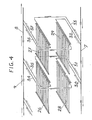
- the radiators placed in the top and bottom are composed of small diameter iron tubes, arranged parallel to the axis of the oven, on the same horizontal plane.
- Each radiator has 3 collectors, which are perpendicular to the tubes, 2 collectors being close to one another, at one end of the tubes, and another collector, parallel to the other 2, placed at the other end of the tubes.
- the oil arrives in one of the 2 collectors which are close to each other, enters the tubes that could be numbered 1, 3, 5, 7, etc. then arrives in the opposite collector, enters the tubes that could be numbered 2, 4, 6, 8, etc. and arrives in the 3rd collector.
- This third manifold is connected to the oil return pipes to the boiler. This arrangement is such that the heat emission is uniform over the entire surface of the radiator.
- the radiators are placed in the sheet metal tunnel whose temperature is at times different from that of the radiators. To avoid any tension between the tunnel and the radiators, the latter rest, by their angles, on 4 supports, integral with the tunnel. On a first support, the radiator is immobilized by bolting. On the second support, placed on the opposite side of the oven, the radiator is simply guided and can move in the direction perpendicular to the axis of the oven. On the other 2 supports the radiator is simply placed and can move in both directions. To avoid tension between the tunnel and the 2 pipes, inlet and outlet of the radiator. these cross the sheet metal of the tunnel, at the places where the radiator cannot move Ion gitudinally with respect to the tunnel.
- the radiators are supplied with oil, via a main pipe, which starts from the boiler placed above the tunnel, descends under the tunnel, follows it near an edge and on its full length.
- This pipe is placed in supports, fixed to the tunnel, in which it can slide effortlessly, when it lengthens or retracts due to variations in its temperature.
- On this pipe are welded as many branches as there are radiators to supply. These branches pass under the tunnel, horizontally, and go up on the opposite face of the tunnel, to feed each radiator.
- the taps feeding the radiators being of small diameter and great length, can, when the main pipeline moves, deform elastically, without tiring, neither the tubes, nor the welds.
- the branches supplying the radiators in particular those located far from the boiler.
- the oil return line to the boiler is analogous to the radiator supply line, but it is placed above the tunnel, along its entire length and also near an edge.
- the radiator return connections are made in the same way as the supply connections, they mount on the face of the op tunnel. placed at the collector, and cross the top of the tunnel, before being welded to this collector. Air is removed from the circuit thus produced automatically, in the direction of oil circulation.
- a temperature regulation in the various parts of the tunnel is carried out by placing on the return connections of the radiators temperature taking probes acting on motorized valves, by means of adjustable thermostats.
- This regulation is much more precise than that which consists in placing probes inside the oven, moreover, the regulation of a radiator has no effect on that of neighboring radiators.
- the control devices, placed above the tunnel, are easily accessible, they are composed of standard elements, built in large series and at a moderate price (the thermostats can be grouped on the control panel of the oven).
- Fig. 1 shows an oven, the body of which is constituted by the sheet metal tunnel 1, in which a metal belt 2 circulates, on which the products to be cooked are arranged.
- Six radiators 3, are arranged in a vault and six other radiators 3, are placed on the floor, under the metal mat 2.
- the boiler 4 Above the tunnel are installed, the boiler 4, the circulation pump 5, and the expansion tank 6 From the boiler leaves the oil distribution pipe 7, placed below the tunnel, on which the connections are welded, supplying the 12 radiators.
- These 2 pipes are supported by collars 9, fixed to the tunnel in which they can slide freely when they lengthen or retract under the effect of temperature variations.
- the pipes 10 and 11, connect the furnace to a central boiler, and the pump 12 ensures the circulation of the oil throughout the circuit.
- a 3-way valve 13 is placed on the suction of the pump 12, which sucks a mixture of oil from the radiators and the boiler.
- the proportion of the 2 sources in the mixture is determined by a thermostat 14, controlling the 3-way valve 13, receiving the indications of a probe 15, placed in contact with the discharge pipe of the pump.
- This device allows the user of the oven to choose the temperature of the oil supplying the radiators and automatically maintains this temperature. This device enables several ovens operating at different temperatures to be supplied by a single boiler.
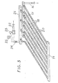
- Fig. 3 shows a radiator, which is supplied by the pipe 16, connected to the manifold 17, on which are welded, at one of their ends the tubes 18. At their other end, these tubes are welded to the manifold 19, on which are also welded the tubes 20, the other end of which is welded to the manifold 21.
- a pipe 22, is welded to the manifold 21 and brings the oil back to the pipe 8, back to the boiler.
- This arrangement of the tubes 18 and 20 makes it possible to have the same average temperature over the entire surface of the radiator, and thus to have a uniform heat emission.
- On the return pipe 22, are placed, a motorized valve 23 and a temperature sensor 24, which controls the motorized valve 23, through the thermostat 25, which is adjusted to the desired temperature. This regulation makes it possible to adjust the oil flow, to the heat requirements and to automatically maintain the temperature of the radiator at a constant value.
Landscapes
- Engineering & Computer Science (AREA)
- Mechanical Engineering (AREA)
- General Engineering & Computer Science (AREA)
- Chemical & Material Sciences (AREA)
- Combustion & Propulsion (AREA)
- Life Sciences & Earth Sciences (AREA)
- Food Science & Technology (AREA)
- Physics & Mathematics (AREA)
- Thermal Sciences (AREA)
- Sustainable Development (AREA)
- Commercial Cooking Devices (AREA)
- Central Heating Systems (AREA)
Priority Applications (1)
| Application Number | Priority Date | Filing Date | Title |
|---|---|---|---|
| AT82901130T ATE10785T1 (de) | 1981-04-22 | 1982-04-20 | Durchlaufofen mit oelumlaufbeheizung zum erwaermen von nahrungsmitteln. |
Applications Claiming Priority (2)
| Application Number | Priority Date | Filing Date | Title |
|---|---|---|---|
| FR8108155A FR2504662A1 (fr) | 1981-04-22 | 1981-04-22 | Four tunnel, a chauffage par circulation d'huile |
| FR8108155 | 1981-04-22 |
Publications (2)
| Publication Number | Publication Date |
|---|---|
| EP0076820A1 EP0076820A1 (fr) | 1983-04-20 |
| EP0076820B1 true EP0076820B1 (fr) | 1984-12-12 |
Family
ID=9257726
Family Applications (1)
| Application Number | Title | Priority Date | Filing Date |
|---|---|---|---|
| EP82901130A Expired EP0076820B1 (fr) | 1981-04-22 | 1982-04-20 | Four tunnel a chauffage par circulation d'huile destine a la cuisson de produits alimentaires |
Country Status (4)
| Country | Link |
|---|---|
| EP (1) | EP0076820B1 (https=) |
| DE (1) | DE3261512D1 (https=) |
| FR (1) | FR2504662A1 (https=) |
| WO (1) | WO1982003681A1 (https=) |
Families Citing this family (9)
| Publication number | Priority date | Publication date | Assignee | Title |
|---|---|---|---|---|
| IT1242657B (it) * | 1989-09-27 | 1994-05-17 | Osuna Luis A Martinez | Forno modulare perfezionato per la cottura d'impasti di pane e di pasticceria |
| IT1249511B (it) * | 1991-03-21 | 1995-02-23 | Pavan Mapimpianti Spa | Impianto di climatizzazione per paste alimentari e simili |
| DE4342634A1 (de) * | 1993-12-14 | 1995-06-22 | Helmut Walter Leicht | Vorrichtung zur Wärmeübertragung, insbesondere in einer Konvektionslötanlage |
| US20060169271A1 (en) * | 2005-01-31 | 2006-08-03 | James Randall | Elevated temperature cooking system |
| DE102006058025A1 (de) * | 2006-12-07 | 2008-06-19 | Krones Ag | Vorrichtung zum Erzeugen von Prozesswärme für eine Verpackungseinrichtung |
| CN107741150A (zh) * | 2017-10-31 | 2018-02-27 | 江苏天舒电器股份有限公司 | 一种无霜、多变量耦合型热泵热风炉的控制系统及其控制方法 |
| CN110024818B (zh) * | 2018-06-27 | 2025-04-01 | 广州焙欧机械设备有限公司 | 一种隧道炉 |
| DE102019212937B3 (de) * | 2019-08-28 | 2020-08-13 | Werner & Pfleiderer Industrielle Backtechnik Gmbh | Durchlauf-Backofen für den kontinuierlichen Backbetrieb |
| CN110966852B (zh) * | 2019-12-21 | 2024-07-12 | 中山市昇洋机械设备有限公司 | 一种肉干烧烤隧道炉 |
Family Cites Families (7)
| Publication number | Priority date | Publication date | Assignee | Title |
|---|---|---|---|---|
| FR435931A (fr) * | 1911-11-03 | 1912-03-13 | Charles Cerri | Four de boulangerie |
| CH200988A (de) * | 1938-06-24 | 1938-11-15 | Max Altorfer | Back- und Dörrofen für Heizflüssigkeitsbetrieb. |
| CH261636A (de) * | 1949-03-16 | 1949-05-31 | Sulzer Ag | Trockenvorrichtung. |
| DE1432923A1 (de) * | 1965-08-18 | 1970-04-02 | Gelsenoel Feuerungstechnik Gmb | Backofen mit mehreren individuell beheizbaren Backmuffeln |
| DE1532919B1 (de) * | 1967-03-13 | 1970-08-27 | Monn Weiss Geb Minet | Umlaufheizung fuer Backoefen |
| AT297184B (de) * | 1968-06-26 | 1972-03-10 | Franz Ing Weiss | Einbrennlackierofen für Durchlaufbetrieb |
| DE2908572A1 (de) * | 1979-03-05 | 1980-09-18 | Sindelar Guenter | Vorrichtung zur thermischen und/oder chemischen und/oder mechanischen behandlung von schuett- oder fliessfaehigem gut |
-
1981
- 1981-04-22 FR FR8108155A patent/FR2504662A1/fr active Granted
-
1982
- 1982-04-20 EP EP82901130A patent/EP0076820B1/fr not_active Expired
- 1982-04-20 DE DE8282901130T patent/DE3261512D1/de not_active Expired
- 1982-04-20 WO PCT/FR1982/000072 patent/WO1982003681A1/fr not_active Ceased
Also Published As
| Publication number | Publication date |
|---|---|
| WO1982003681A1 (fr) | 1982-10-28 |
| DE3261512D1 (en) | 1985-01-24 |
| FR2504662A1 (fr) | 1982-10-29 |
| FR2504662B1 (https=) | 1985-03-29 |
| EP0076820A1 (fr) | 1983-04-20 |
Similar Documents
| Publication | Publication Date | Title |
|---|---|---|
| EP0076820B1 (fr) | Four tunnel a chauffage par circulation d'huile destine a la cuisson de produits alimentaires | |
| EP1206422B1 (fr) | Perfectionnements apportes aux etenderies de recuisson de verre plat | |
| US4852524A (en) | Gas fired water heater | |
| US4577435A (en) | Micro-climate temperature control apparatus | |
| SE7907782L (sv) | Anordning for avgivning av fluidum | |
| US761596A (en) | Solar heater. | |
| CN110057865A (zh) | 船用蒸汽发生器二次侧沸腾传热分析装置 | |
| US6408842B1 (en) | Oven | |
| UA87279C2 (ru) | Прямоточный парогенератор горизонтального типа конструкции и способ для эксплуатации прямоточного парогенератора | |
| FR2476291A1 (fr) | Four de cuisson multizone a chauffage indirect et a transporteur | |
| FR2506908A1 (fr) | Chaudiere electrique | |
| JPH08242703A (ja) | 温室内の加温装置 | |
| FR2571834A2 (fr) | Four tunnel, a chauffage par circulation d'huile | |
| KR810002258Y1 (ko) | 보일러의 식수 가온장치 | |
| US20060169271A1 (en) | Elevated temperature cooking system | |
| EP0790471B1 (fr) | Perfectionnements aux dispositifs de chauffage central à deux circuits de caractéristiques thermiques différentes | |
| FR2982933A1 (fr) | Installation de distribution d'air pour terrasse ou analogue | |
| JPS59189250A (ja) | 気体を送入する液体用熱交換器 | |
| SU1755017A1 (ru) | Воздухоподогреватель | |
| SU1186148A2 (ru) | Устройство дл регулировани температуры воздуха блочных теплиц с трубным обогревом | |
| BE559978A (https=) | ||
| CN113819649A (zh) | 一种化工专用加热炉 | |
| US1304531A (en) | bergmann | |
| US2032486A (en) | Water heater | |
| BE672350A (https=) |
Legal Events
| Date | Code | Title | Description |
|---|---|---|---|
| PUAI | Public reference made under article 153(3) epc to a published international application that has entered the european phase |
Free format text: ORIGINAL CODE: 0009012 |
|
| 17P | Request for examination filed |
Effective date: 19821216 |
|
| AK | Designated contracting states |
Designated state(s): AT CH DE GB LI LU NL SE |
|
| GRAA | (expected) grant |
Free format text: ORIGINAL CODE: 0009210 |
|
| AK | Designated contracting states |
Designated state(s): AT CH DE GB LI LU NL SE |
|
| PG25 | Lapsed in a contracting state [announced via postgrant information from national office to epo] |
Ref country code: SE Effective date: 19841212 Ref country code: NL Effective date: 19841212 Ref country code: AT Effective date: 19841212 |
|
| REF | Corresponds to: |
Ref document number: 10785 Country of ref document: AT Date of ref document: 19841215 Kind code of ref document: T |
|
| REF | Corresponds to: |
Ref document number: 3261512 Country of ref document: DE Date of ref document: 19850124 |
|
| PG25 | Lapsed in a contracting state [announced via postgrant information from national office to epo] |
Ref country code: LU Free format text: LAPSE BECAUSE OF NON-PAYMENT OF DUE FEES Effective date: 19850430 Ref country code: LI Effective date: 19850430 Ref country code: CH Effective date: 19850430 |
|
| NLV1 | Nl: lapsed or annulled due to failure to fulfill the requirements of art. 29p and 29m of the patents act | ||
| PLBE | No opposition filed within time limit |
Free format text: ORIGINAL CODE: 0009261 |
|
| STAA | Information on the status of an ep patent application or granted ep patent |
Free format text: STATUS: NO OPPOSITION FILED WITHIN TIME LIMIT |
|
| 26N | No opposition filed | ||
| REG | Reference to a national code |
Ref country code: CH Ref legal event code: PL |
|
| PG25 | Lapsed in a contracting state [announced via postgrant information from national office to epo] |
Ref country code: DE Effective date: 19860101 |
|
| GBPC | Gb: european patent ceased through non-payment of renewal fee | ||
| PG25 | Lapsed in a contracting state [announced via postgrant information from national office to epo] |
Ref country code: GB Effective date: 19881121 |