EP0076716A1 - Installation frigorifique à multimotocompresseurs - Google Patents
Installation frigorifique à multimotocompresseurs Download PDFInfo
- Publication number
- EP0076716A1 EP0076716A1 EP82401687A EP82401687A EP0076716A1 EP 0076716 A1 EP0076716 A1 EP 0076716A1 EP 82401687 A EP82401687 A EP 82401687A EP 82401687 A EP82401687 A EP 82401687A EP 0076716 A1 EP0076716 A1 EP 0076716A1
- Authority
- EP
- European Patent Office
- Prior art keywords
- points
- high pressure
- pressure stage
- stage
- compressors
- Prior art date
- Legal status (The legal status is an assumption and is not a legal conclusion. Google has not performed a legal analysis and makes no representation as to the accuracy of the status listed.)
- Withdrawn
Links
- 238000009434 installation Methods 0.000 title claims abstract description 31
- 238000005057 refrigeration Methods 0.000 title claims description 39
- 239000003507 refrigerant Substances 0.000 claims abstract description 43
- 238000001704 evaporation Methods 0.000 claims abstract description 40
- 230000008020 evaporation Effects 0.000 claims abstract description 40
- 150000001875 compounds Chemical class 0.000 claims abstract description 17
- 239000007788 liquid Substances 0.000 claims abstract description 13
- 239000003638 chemical reducing agent Substances 0.000 description 3
- 238000001816 cooling Methods 0.000 description 3
- 238000005461 lubrication Methods 0.000 description 3
- 238000000034 method Methods 0.000 description 3
- GISRWBROCYNDME-PELMWDNLSA-N F[C@H]1[C@H]([C@H](NC1=O)COC1=NC=CC2=CC(=C(C=C12)OC)C(=O)N)C Chemical compound F[C@H]1[C@H]([C@H](NC1=O)COC1=NC=CC2=CC(=C(C=C12)OC)C(=O)N)C GISRWBROCYNDME-PELMWDNLSA-N 0.000 description 2
- 230000006835 compression Effects 0.000 description 2
- 238000007906 compression Methods 0.000 description 2
- 238000004519 manufacturing process Methods 0.000 description 2
- 230000015556 catabolic process Effects 0.000 description 1
- 230000005494 condensation Effects 0.000 description 1
- 238000009833 condensation Methods 0.000 description 1
- 238000010276 construction Methods 0.000 description 1
- 239000002826 coolant Substances 0.000 description 1
- 238000010586 diagram Methods 0.000 description 1
- 230000009977 dual effect Effects 0.000 description 1
- 230000001747 exhibiting effect Effects 0.000 description 1
- 239000000203 mixture Substances 0.000 description 1
- XULSCZPZVQIMFM-IPZQJPLYSA-N odevixibat Chemical compound C12=CC(SC)=C(OCC(=O)N[C@@H](C(=O)N[C@@H](CC)C(O)=O)C=3C=CC(O)=CC=3)C=C2S(=O)(=O)NC(CCCC)(CCCC)CN1C1=CC=CC=C1 XULSCZPZVQIMFM-IPZQJPLYSA-N 0.000 description 1
- 230000002747 voluntary effect Effects 0.000 description 1
Images


Classifications
-
- F—MECHANICAL ENGINEERING; LIGHTING; HEATING; WEAPONS; BLASTING
- F25—REFRIGERATION OR COOLING; COMBINED HEATING AND REFRIGERATION SYSTEMS; HEAT PUMP SYSTEMS; MANUFACTURE OR STORAGE OF ICE; LIQUEFACTION SOLIDIFICATION OF GASES
- F25B—REFRIGERATION MACHINES, PLANTS OR SYSTEMS; COMBINED HEATING AND REFRIGERATION SYSTEMS; HEAT PUMP SYSTEMS
- F25B1/00—Compression machines, plants or systems with non-reversible cycle
- F25B1/10—Compression machines, plants or systems with non-reversible cycle with multi-stage compression
-
- F—MECHANICAL ENGINEERING; LIGHTING; HEATING; WEAPONS; BLASTING
- F25—REFRIGERATION OR COOLING; COMBINED HEATING AND REFRIGERATION SYSTEMS; HEAT PUMP SYSTEMS; MANUFACTURE OR STORAGE OF ICE; LIQUEFACTION SOLIDIFICATION OF GASES
- F25B—REFRIGERATION MACHINES, PLANTS OR SYSTEMS; COMBINED HEATING AND REFRIGERATION SYSTEMS; HEAT PUMP SYSTEMS
- F25B2400/00—General features or devices for refrigeration machines, plants or systems, combined heating and refrigeration systems or heat-pump systems, i.e. not limited to a particular subgroup of F25B
- F25B2400/07—Details of compressors or related parts
- F25B2400/075—Details of compressors or related parts with parallel compressors
-
- F—MECHANICAL ENGINEERING; LIGHTING; HEATING; WEAPONS; BLASTING
- F25—REFRIGERATION OR COOLING; COMBINED HEATING AND REFRIGERATION SYSTEMS; HEAT PUMP SYSTEMS; MANUFACTURE OR STORAGE OF ICE; LIQUEFACTION SOLIDIFICATION OF GASES
- F25B—REFRIGERATION MACHINES, PLANTS OR SYSTEMS; COMBINED HEATING AND REFRIGERATION SYSTEMS; HEAT PUMP SYSTEMS
- F25B2400/00—General features or devices for refrigeration machines, plants or systems, combined heating and refrigeration systems or heat-pump systems, i.e. not limited to a particular subgroup of F25B
- F25B2400/13—Economisers
Definitions
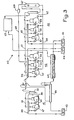
- the present invention relates to a refrigeration installation with multi-compressors.
- a known compound refrigeration unit 1 usually comprises, on the one hand, a low pressure moiocompressor 2 which sucks expanded refrigerant gas at the pressure Po from the points of use 3 at a single low evaporation temperature for example -38 ° C., the compresses to the pressure Pm and discharges it into an intermediate bottle 4 where the compressed refrigerant gas is desuperheated, and on the other hand a high pressure motor compressor 5 which sucks desuperheated refrigerant gas from the bottle 4, compresses it to the pressure Pk and discharges it into a condenser 6.
- the condensed condenser coming from the condenser 6 accumulates in the form of liquid in a tank 7 and passes partly in a coil 8 arranged in the lower zone of the intermediate bottle 4, and partly through a pressure reducer 9 in the bottle 4 where, by evaporation, it desuperheats your vapors of compressed compressed refrigerant by the low pressure compressor 2, and under cools the liquid refrigerant current which borrows the coil 8 to go and relax through the pressure reducer 10 in the points of use 3 at a single low evaporation temperature -38 ° C for example .
- a refrigeration installation produced according to the invention is a refrigeration installation with multi-compressors having in its refrigeration circuit, at least on the one hand a low pressure stage and a high pressure stage which have their own points of use and whose common suction collectors of the motor compressors are maintained at pressures, equal respectively to the evaporation pressures tl and t2 of the points of use of these two stages, the capacity and the number of the compressors of the low-pressure stage are provided to supply correctly with refrigerant the points of use specific to this stage, and the capacity and the number of compressors of the high pressure stage are determined to supply the points of use of these two stages correctly with refrigerant, the refrigerant gas discharged from the low pressure stage being admitted into the common suction manifold of the high pressure stage at the same time as the expanded refrigerant gas coming from the own points of use of this high pressure stage,
- the compound refrigeration installation 11 comprises a low pressure stage 12 and a high pressure stage 13 having respectively points of use 14 at an evaporation temperature tl , equal to -38 ° C, and points of use 15 at an evaporation temperature t2, equal to -10 ° C.
- the low pressure stage 12 comprises two motor compressors 16, 17 whose total capacity is sufficient to supply refrigerant to the points of use 14 while the high pressure stage comprises three motor compressors 18, 19, 20 whose total capacity is determined for supply the refrigeration points 14 and 15 of the two stages 12 and 13 correctly.
- the common suction manifold 21 of the compressors 16, 17 of the low pressure stage is maintained at a pressure equal to the evaporation pressure - 38 ° C at the points of use 14.
- the motor compressors 16 and 17 draw in expanded refrigerant gas coming from the points of use 14 and discharge it through their common discharge line 22 and an oil separator 23, into a common suction manifold 24 of the high pressure stage motor compressors 13.
- the motor compressors 18, 19, 20 from the high pressure stage 13 suck in refrigerant gas being in their suction manifold 24 and discharge it through their common discharge pipe 25 and an oil separator 26, into a condenser 27.
- the refrigerant gas condensed in the form of liquid passes from the condenser 27 into a reservoir 28 common to the two stages 12 and 13 which feeds under the same high pressure both the points of use 14 and 15 of these two stages.
- a counter-current exchanger 29 is mounted between these two stages 12 and 13 for firstly under cooling the stream of liquid refrigerant supplying the points of use 14 of the low pressure stage 12 and secondly desuperheating the refrigerant gas discharged by the low pressure stage 12 into the suction manifold 24 of the high pressure stage 13.
- the superheated expanded refrigerant gas coming from the points of use at evaporation temperature -10 ° C. is not cooled or desuperheated before to be vacuumed and compressed by motor compressors.
- the casings of the compressors of the motor compressors 16 and 17 of the low pressure stage 12 are connected to each other by a large section pipe 32 whose dual function is to allow the oil to balance in the compressor crankcases and to have the same pressure in these crankcases.
- the oil recovered by the oil separator 26 as well as gaseous refrigerant entrained by the oil are brought into an oil tank 33, the lower part of which is connected to the casings of the motor-compressors 18, 19, 20 by a pipe 34 and float devices 35, 36, 37 and the upper part is connected to the common suction manifold 24 of the compressors by a pipe 38 and a calibrated valve 39 which creates a pressure drop of approximately one bar for bringing the oil tank 33 to a pressure of one bar higher than the pressure in the casings of the motor compressors 18, 19, 20.
- the oil in the tank 33 is thus brought under a pressure difference of one bar, in each one. of these casings through devices 35, 36, 37, the float of which maintains the oil at a preset level.
- the compound refrigeration installation 40 comprises in its refrigeration circuit, on the one hand like that of the first example (FIG. 2) a low pressure stage 41 and a high pressure stage 42 mounted in compound with their own points of use 43, 44 whose evaporation temperatures are respectively -38 ° C and -10 ° C, and on the other hand by a second high pressure stage 45 having its own points of use whose evaporation temperature t3 of the order of -3 ° C to -8 ° C, t3 chosen in this example is equal to -6 ° C.
- the low pressure stage 41 comprises two motor compressors 47, 48, a common suction manifold 49, an oil separator 50 and a common discharge line 51.
- the first high pressure stage 42 comprises three motor compressors 52, 53, 54 and a common collector suction 55 which receives both refrigerant gas coming from its own points of use 44 and refrigerant gas discharged from the low pressure stage 41.
- An exchanger 56 mounted between these two stages 41 for sub-cooling the liquid refrigerant supplying the points of use 43 of the low pressure stage 41 and desuperheating the refrigerant gas discharged from this low pressure stage and the expanded gas coming from the points of use 44 of this first high pressure stage 42 in the common suction manifold 55.
- the second high pressure stage 45 comprises three motor compressors 57, 58, 59, a common suction manifold 60, independent of the suction manifold 55 of the first high pressure stage 42 and a common discharge line 61 for all the six motor compressors of these two high pressure stages 42 and 45.
- the suction manifold 55 of the first high pressure stage 42 is maintained at a pressure equal to the evaporation pressure -10 ° C of its points of use 44 while the suction manifold 60 of the second high pressure stage 45 is maintained at a pressure equal to an evaporation pressure -6 ° C of its own points of use 46.
- the refrigerant gas compressed by the motor compressors of the two high pressure stages 42, 45 is discharged through the common discharge pipe 61 and an oil separator 62 in a condenser 63 common to the three stages 41, 42, 45.
- the refrigerant in the form of liquid from the condenser 63 accumulates in a reservoir 64 common to these three stages 41, 42, 45 before going to supply the points of use 43, 44, 46 respectively under the same high pressure.
- a known independent refrigeration plant having points of use at an evaporation temperature of -10 ° C. or a refrigeration plant 11 of the first example illustrated in FIG. 2 can at its points of use 15 also supply points of use at a higher evaporation temperature t3 for example -5 ° C or -6 ° C.
- a higher evaporation temperature t3 for example -5 ° C or -6 ° C.
- Evaporation at -5 ° C brings a gain of around twenty percent in refrigeration efficiency at points of use at -5 ° C compared to evaporation at -10 ° C at points of use with valves at constant pressure to maintain -5 ° C evaporation in the evaporator.
- the casings of the compressors of the low pressure stage 41 are also connected to each other, as in those of the first example, by a pipe of large section 65 so as to have in these crankcases have the same pressure and a preset oil level while in the high pressure stages 42, 45, the crankcases of the motor compressors are connected by float devices and a common line 66 to the lower part of an oil tank 67, the upper part of which is connected to the common suction manifold 55 of the high-pressure first stage motor-compressors 42, through a pipe 68 and a calibrated valve 69 which creates, like that in the first example, a pressure drop of approximately one bar for put the oil tank 67 at a pressure one bar higher than the pressure in the compressor housings.
Landscapes
- Engineering & Computer Science (AREA)
- Physics & Mathematics (AREA)
- Mechanical Engineering (AREA)
- Thermal Sciences (AREA)
- General Engineering & Computer Science (AREA)
- Compressor (AREA)
- Applications Or Details Of Rotary Compressors (AREA)
Applications Claiming Priority (2)
| Application Number | Priority Date | Filing Date | Title |
|---|---|---|---|
| FR8118136A FR2513747A1 (fr) | 1981-09-25 | 1981-09-25 | Installation frigorifique a multimotocompresseurs |
| FR8118136 | 1981-09-25 |
Publications (1)
| Publication Number | Publication Date |
|---|---|
| EP0076716A1 true EP0076716A1 (fr) | 1983-04-13 |
Family
ID=9262479
Family Applications (1)
| Application Number | Title | Priority Date | Filing Date |
|---|---|---|---|
| EP82401687A Withdrawn EP0076716A1 (fr) | 1981-09-25 | 1982-09-16 | Installation frigorifique à multimotocompresseurs |
Country Status (3)
| Country | Link |
|---|---|
| EP (1) | EP0076716A1 (OSRAM) |
| ES (1) | ES515937A0 (OSRAM) |
| FR (1) | FR2513747A1 (OSRAM) |
Cited By (9)
| Publication number | Priority date | Publication date | Assignee | Title |
|---|---|---|---|---|
| FR2557962A1 (fr) * | 1984-01-11 | 1985-07-12 | Copeland Corp | Dispositif de refrigeration a deux etages, au fonctionnement souple et au rendement eleve |
| FR2598788A1 (fr) * | 1986-05-15 | 1987-11-20 | Copeland Corp | Dispositif de refrigeration. |
| US4748820A (en) * | 1984-01-11 | 1988-06-07 | Copeland Corporation | Refrigeration system |
| WO1990000709A1 (en) * | 1988-07-08 | 1990-01-25 | Olson Ref. - H Olson Refrigeration Ab | Intermediate cooling aggregate in a cooling and freezing plant |
| EP1050723A3 (de) * | 1999-05-05 | 2002-08-14 | Linde Aktiengesellschaft | Kälteanlage und Verfahren zum Betreiben einer Kälteanlage |
| WO2006022829A1 (en) * | 2004-08-09 | 2006-03-02 | Carrier Corporation | Co2 refrigeration circuit with sub-cooling of the liquid refrigerant against the receiver flash gas and method for operating the same |
| WO2007016944A1 (en) * | 2005-08-08 | 2007-02-15 | Carrier Corporation | Refrigeration system comprising multiple refrigeration consumer devices |
| EP2021703A4 (en) * | 2006-06-01 | 2012-02-15 | Carrier Corp | MULTI-STAGE COMPRESSOR UNIT FOR REFRIGERATION SYSTEM |
| EP3064866A1 (en) * | 2015-03-04 | 2016-09-07 | Heatcraft Refrigeration Products LLC | Modulated oversized compressor configuration for flash gas bypass in a carbon dioxide refrigeration system |
Families Citing this family (1)
| Publication number | Priority date | Publication date | Assignee | Title |
|---|---|---|---|---|
| US20240053065A1 (en) * | 2022-08-12 | 2024-02-15 | BMIL Technology, LLC | Low gwp cascade refrigeration system |
Citations (6)
| Publication number | Priority date | Publication date | Assignee | Title |
|---|---|---|---|---|
| DE281761C (OSRAM) * | ||||
| FR458034A (fr) * | 1912-07-27 | 1913-10-01 | Societe De Moteurs A Gaz Et D Industrie Mecanique | Perfectionnements apportés à l'établissement des installations frigorifiques |
| DE1501115A1 (de) * | 1951-01-28 | 1969-10-09 | Refrigeration Specialties Co | Kaeltesystem |
| FR2182137A1 (OSRAM) * | 1972-04-27 | 1973-12-07 | Svenska Rotor Maskiner Ab | |
| FR2341109A1 (fr) * | 1976-02-13 | 1977-09-09 | Doomernik Cornelis | Accumulateur de froid |
| US4151724A (en) * | 1977-06-13 | 1979-05-01 | Frick Company | Pressurized refrigerant feed with recirculation for compound compression refrigeration systems |
-
1981
- 1981-09-25 FR FR8118136A patent/FR2513747A1/fr active Granted
-
1982
- 1982-09-16 EP EP82401687A patent/EP0076716A1/fr not_active Withdrawn
- 1982-09-24 ES ES515937A patent/ES515937A0/es active Granted
Patent Citations (6)
| Publication number | Priority date | Publication date | Assignee | Title |
|---|---|---|---|---|
| DE281761C (OSRAM) * | ||||
| FR458034A (fr) * | 1912-07-27 | 1913-10-01 | Societe De Moteurs A Gaz Et D Industrie Mecanique | Perfectionnements apportés à l'établissement des installations frigorifiques |
| DE1501115A1 (de) * | 1951-01-28 | 1969-10-09 | Refrigeration Specialties Co | Kaeltesystem |
| FR2182137A1 (OSRAM) * | 1972-04-27 | 1973-12-07 | Svenska Rotor Maskiner Ab | |
| FR2341109A1 (fr) * | 1976-02-13 | 1977-09-09 | Doomernik Cornelis | Accumulateur de froid |
| US4151724A (en) * | 1977-06-13 | 1979-05-01 | Frick Company | Pressurized refrigerant feed with recirculation for compound compression refrigeration systems |
Cited By (12)
| Publication number | Priority date | Publication date | Assignee | Title |
|---|---|---|---|---|
| FR2557962A1 (fr) * | 1984-01-11 | 1985-07-12 | Copeland Corp | Dispositif de refrigeration a deux etages, au fonctionnement souple et au rendement eleve |
| US4748820A (en) * | 1984-01-11 | 1988-06-07 | Copeland Corporation | Refrigeration system |
| US4787211A (en) * | 1984-07-30 | 1988-11-29 | Copeland Corporation | Refrigeration system |
| FR2598788A1 (fr) * | 1986-05-15 | 1987-11-20 | Copeland Corp | Dispositif de refrigeration. |
| WO1990000709A1 (en) * | 1988-07-08 | 1990-01-25 | Olson Ref. - H Olson Refrigeration Ab | Intermediate cooling aggregate in a cooling and freezing plant |
| EP1050723A3 (de) * | 1999-05-05 | 2002-08-14 | Linde Aktiengesellschaft | Kälteanlage und Verfahren zum Betreiben einer Kälteanlage |
| WO2006022829A1 (en) * | 2004-08-09 | 2006-03-02 | Carrier Corporation | Co2 refrigeration circuit with sub-cooling of the liquid refrigerant against the receiver flash gas and method for operating the same |
| WO2007016944A1 (en) * | 2005-08-08 | 2007-02-15 | Carrier Corporation | Refrigeration system comprising multiple refrigeration consumer devices |
| EP2021703A4 (en) * | 2006-06-01 | 2012-02-15 | Carrier Corp | MULTI-STAGE COMPRESSOR UNIT FOR REFRIGERATION SYSTEM |
| EP3064866A1 (en) * | 2015-03-04 | 2016-09-07 | Heatcraft Refrigeration Products LLC | Modulated oversized compressor configuration for flash gas bypass in a carbon dioxide refrigeration system |
| CN105937815A (zh) * | 2015-03-04 | 2016-09-14 | 西克制冷产品有限责任公司 | 用于co2制冷系统的闪蒸气体旁路的调整的超大压缩机配置 |
| US9726411B2 (en) | 2015-03-04 | 2017-08-08 | Heatcraft Refrigeration Products L.L.C. | Modulated oversized compressors configuration for flash gas bypass in a carbon dioxide refrigeration system |
Also Published As
| Publication number | Publication date |
|---|---|
| FR2513747B1 (OSRAM) | 1983-12-02 |
| FR2513747A1 (fr) | 1983-04-01 |
| ES8308627A1 (es) | 1983-09-16 |
| ES515937A0 (es) | 1983-09-16 |
Similar Documents
| Publication | Publication Date | Title |
|---|---|---|
| BE1009557A5 (fr) | Methode et appareillage de prerefroidissement d'air avec dispositif de refrigeration a contact indirect. | |
| KR100285665B1 (ko) | 냉동장치 | |
| US5079929A (en) | Multi-stage refrigeration apparatus and method | |
| EP0076716A1 (fr) | Installation frigorifique à multimotocompresseurs | |
| US6185944B1 (en) | Refrigeration system with a compressor-pump unit and a liquid-injection desuperheating line | |
| FR2545589A1 (fr) | Procede et appareil de refroidissement et liquefaction d'au moins un gaz a bas point d'ebullition, tel que par exemple du gaz naturel | |
| FR2510718A1 (fr) | Station de soutirage de gaz | |
| FR2476240A1 (fr) | Appareil de recuperation d'energie pour installation de compresseur de gaz | |
| US5408835A (en) | Apparatus and method for preventing ice from forming on a refrigeration system | |
| EP0644390B1 (fr) | Procédé et ensemble de compression d'un gaz | |
| US5167130A (en) | Screw compressor system for reverse cycle defrost having relief regulator valve and economizer port | |
| EP2827068B1 (fr) | Pompe à chaleur en cascade | |
| US6349564B1 (en) | Refrigeration system | |
| BE1009886A5 (fr) | Procede et dispositif pour la production d'eau par condensation de l'humidite presente dans l'air atmospherique. | |
| WO2011055045A1 (fr) | Système de vaporisation d'un fluide cryogénique avec des échangeurs centralisés | |
| EP0080916A1 (fr) | Installation frigorifique à rendement amélioré à multimotocompresseurs | |
| RU2079041C1 (ru) | Способ использования энергии технологических перепадов давления газа в системах транспорта и устройство для его осуществления | |
| CN212081732U (zh) | 一种压缩式真空预冷装置 | |
| FR2943125A1 (fr) | Procede de liquefaction de gaz naturel a cycle combine | |
| FR3137746A1 (fr) | Dispositif et procédé de liquéfaction d’un fluide. | |
| FR2560974A1 (fr) | Installation de production de froid a moyen de stockage et de destockage du travail des motocompresseurs | |
| SU781511A1 (ru) | Способ работы компрессионной холодильной машины | |
| SU826157A1 (ru) | Двухступенчатая холодильная установка 1 | |
| CN2450606Y (zh) | 满液式冷媒循环系统的冰水机 | |
| FR2514112A1 (fr) | Installation frigorifique a points d'utilisation a temperatures differentes d'evaporation |
Legal Events
| Date | Code | Title | Description |
|---|---|---|---|
| PUAI | Public reference made under article 153(3) epc to a published international application that has entered the european phase |
Free format text: ORIGINAL CODE: 0009012 |
|
| AK | Designated contracting states |
Designated state(s): AT BE CH DE FR GB IT LI LU NL SE |
|
| 17P | Request for examination filed |
Effective date: 19830614 |
|
| RAP3 | Party data changed (applicant data changed or rights of an application transferred) |
Owner name: FSB |
|
| STAA | Information on the status of an ep patent application or granted ep patent |
Free format text: STATUS: THE APPLICATION IS DEEMED TO BE WITHDRAWN |
|
| 18D | Application deemed to be withdrawn |
Effective date: 19881202 |
|
| APAF | Appeal reference modified |
Free format text: ORIGINAL CODE: EPIDOSCREFNE |
|
| RIN1 | Information on inventor provided before grant (corrected) |
Inventor name: SANZEY, EMILE Inventor name: DEMAN, PIERRE |