EP0076626B1 - Gitter für Bleiakkumulator und Verfahren zu seiner Herstellung - Google Patents
Gitter für Bleiakkumulator und Verfahren zu seiner Herstellung Download PDFInfo
- Publication number
- EP0076626B1 EP0076626B1 EP82305133A EP82305133A EP0076626B1 EP 0076626 B1 EP0076626 B1 EP 0076626B1 EP 82305133 A EP82305133 A EP 82305133A EP 82305133 A EP82305133 A EP 82305133A EP 0076626 B1 EP0076626 B1 EP 0076626B1
- Authority
- EP
- European Patent Office
- Prior art keywords
- lead
- grid
- grid structure
- rib
- active material
- Prior art date
- Legal status (The legal status is an assumption and is not a legal conclusion. Google has not performed a legal analysis and makes no representation as to the accuracy of the status listed.)
- Expired
Links
- 238000000034 method Methods 0.000 title claims description 11
- 238000004519 manufacturing process Methods 0.000 title claims description 9
- 238000003860 storage Methods 0.000 title claims description 9
- 229910000978 Pb alloy Inorganic materials 0.000 claims description 48
- 239000011149 active material Substances 0.000 claims description 44
- -1 polypropylene Polymers 0.000 claims description 27
- 239000004743 Polypropylene Substances 0.000 claims description 25
- 229920001155 polypropylene Polymers 0.000 claims description 25
- 229920003002 synthetic resin Polymers 0.000 claims description 25
- 239000000057 synthetic resin Substances 0.000 claims description 25
- 239000003365 glass fiber Substances 0.000 claims description 16
- 239000011248 coating agent Substances 0.000 claims description 10
- 238000000576 coating method Methods 0.000 claims description 10
- 239000002253 acid Substances 0.000 claims description 7
- 238000001816 cooling Methods 0.000 claims description 2
- 239000010408 film Substances 0.000 description 36
- 238000007654 immersion Methods 0.000 description 11
- 239000010409 thin film Substances 0.000 description 11
- 239000002131 composite material Substances 0.000 description 8
- 239000003792 electrolyte Substances 0.000 description 5
- 238000009792 diffusion process Methods 0.000 description 4
- 238000001746 injection moulding Methods 0.000 description 4
- 238000002844 melting Methods 0.000 description 4
- 230000008018 melting Effects 0.000 description 4
- 230000008569 process Effects 0.000 description 4
- 238000003491 array Methods 0.000 description 3
- 230000007423 decrease Effects 0.000 description 3
- 238000005429 filling process Methods 0.000 description 3
- 238000010438 heat treatment Methods 0.000 description 3
- 239000010410 layer Substances 0.000 description 3
- 239000000463 material Substances 0.000 description 3
- 230000009467 reduction Effects 0.000 description 3
- 229920002430 Fibre-reinforced plastic Polymers 0.000 description 2
- 239000004698 Polyethylene Substances 0.000 description 2
- 229910045601 alloy Inorganic materials 0.000 description 2
- 239000000956 alloy Substances 0.000 description 2
- 230000015572 biosynthetic process Effects 0.000 description 2
- 238000005266 casting Methods 0.000 description 2
- 238000010276 construction Methods 0.000 description 2
- 238000005520 cutting process Methods 0.000 description 2
- 230000000694 effects Effects 0.000 description 2
- 239000011151 fibre-reinforced plastic Substances 0.000 description 2
- 239000007888 film coating Substances 0.000 description 2
- 238000009501 film coating Methods 0.000 description 2
- 230000005484 gravity Effects 0.000 description 2
- 239000011159 matrix material Substances 0.000 description 2
- 239000002184 metal Substances 0.000 description 2
- 238000000465 moulding Methods 0.000 description 2
- 238000007254 oxidation reaction Methods 0.000 description 2
- 239000002245 particle Substances 0.000 description 2
- 239000008188 pellet Substances 0.000 description 2
- 229920000573 polyethylene Polymers 0.000 description 2
- 229920000915 polyvinyl chloride Polymers 0.000 description 2
- KXGFMDJXCMQABM-UHFFFAOYSA-N 2-methoxy-6-methylphenol Chemical compound [CH]OC1=CC=CC([CH])=C1O KXGFMDJXCMQABM-UHFFFAOYSA-N 0.000 description 1
- 230000002411 adverse Effects 0.000 description 1
- 229910052787 antimony Inorganic materials 0.000 description 1
- WATWJIUSRGPENY-UHFFFAOYSA-N antimony atom Chemical compound [Sb] WATWJIUSRGPENY-UHFFFAOYSA-N 0.000 description 1
- 238000005422 blasting Methods 0.000 description 1
- 230000008859 change Effects 0.000 description 1
- 239000000470 constituent Substances 0.000 description 1
- 239000000356 contaminant Substances 0.000 description 1
- 230000003247 decreasing effect Effects 0.000 description 1
- 238000004299 exfoliation Methods 0.000 description 1
- 238000002474 experimental method Methods 0.000 description 1
- 239000000446 fuel Substances 0.000 description 1
- 230000006872 improvement Effects 0.000 description 1
- 229910010272 inorganic material Inorganic materials 0.000 description 1
- 239000011147 inorganic material Substances 0.000 description 1
- 238000009413 insulation Methods 0.000 description 1
- 230000001788 irregular Effects 0.000 description 1
- 239000005011 phenolic resin Substances 0.000 description 1
- 229920001568 phenolic resin Polymers 0.000 description 1
- 239000004033 plastic Substances 0.000 description 1
- 229920003023 plastic Polymers 0.000 description 1
- 239000004800 polyvinyl chloride Substances 0.000 description 1
- 230000002035 prolonged effect Effects 0.000 description 1
- 230000002787 reinforcement Effects 0.000 description 1
- 229920005989 resin Polymers 0.000 description 1
- 239000011347 resin Substances 0.000 description 1
- 238000005476 soldering Methods 0.000 description 1
- 238000000638 solvent extraction Methods 0.000 description 1
- 239000007921 spray Substances 0.000 description 1
- 238000005507 spraying Methods 0.000 description 1
- 239000002344 surface layer Substances 0.000 description 1
- 239000000725 suspension Substances 0.000 description 1
- 229920005992 thermoplastic resin Polymers 0.000 description 1
- 238000009827 uniform distribution Methods 0.000 description 1
- 238000003466 welding Methods 0.000 description 1
Images


Classifications
-
- H—ELECTRICITY
- H01—ELECTRIC ELEMENTS
- H01M—PROCESSES OR MEANS, e.g. BATTERIES, FOR THE DIRECT CONVERSION OF CHEMICAL ENERGY INTO ELECTRICAL ENERGY
- H01M4/00—Electrodes
- H01M4/02—Electrodes composed of, or comprising, active material
- H01M4/64—Carriers or collectors
- H01M4/70—Carriers or collectors characterised by shape or form
- H01M4/72—Grids
- H01M4/73—Grids for lead-acid accumulators, e.g. frame plates
-
- H—ELECTRICITY
- H01—ELECTRIC ELEMENTS
- H01M—PROCESSES OR MEANS, e.g. BATTERIES, FOR THE DIRECT CONVERSION OF CHEMICAL ENERGY INTO ELECTRICAL ENERGY
- H01M4/00—Electrodes
- H01M4/02—Electrodes composed of, or comprising, active material
- H01M4/64—Carriers or collectors
- H01M4/82—Multi-step processes for manufacturing carriers for lead-acid accumulators
-
- Y—GENERAL TAGGING OF NEW TECHNOLOGICAL DEVELOPMENTS; GENERAL TAGGING OF CROSS-SECTIONAL TECHNOLOGIES SPANNING OVER SEVERAL SECTIONS OF THE IPC; TECHNICAL SUBJECTS COVERED BY FORMER USPC CROSS-REFERENCE ART COLLECTIONS [XRACs] AND DIGESTS
- Y02—TECHNOLOGIES OR APPLICATIONS FOR MITIGATION OR ADAPTATION AGAINST CLIMATE CHANGE
- Y02E—REDUCTION OF GREENHOUSE GAS [GHG] EMISSIONS, RELATED TO ENERGY GENERATION, TRANSMISSION OR DISTRIBUTION
- Y02E60/00—Enabling technologies; Technologies with a potential or indirect contribution to GHG emissions mitigation
- Y02E60/10—Energy storage using batteries
-
- Y—GENERAL TAGGING OF NEW TECHNOLOGICAL DEVELOPMENTS; GENERAL TAGGING OF CROSS-SECTIONAL TECHNOLOGIES SPANNING OVER SEVERAL SECTIONS OF THE IPC; TECHNICAL SUBJECTS COVERED BY FORMER USPC CROSS-REFERENCE ART COLLECTIONS [XRACs] AND DIGESTS
- Y10—TECHNICAL SUBJECTS COVERED BY FORMER USPC
- Y10T—TECHNICAL SUBJECTS COVERED BY FORMER US CLASSIFICATION
- Y10T29/00—Metal working
- Y10T29/10—Battery-grid making
-
- Y—GENERAL TAGGING OF NEW TECHNOLOGICAL DEVELOPMENTS; GENERAL TAGGING OF CROSS-SECTIONAL TECHNOLOGIES SPANNING OVER SEVERAL SECTIONS OF THE IPC; TECHNICAL SUBJECTS COVERED BY FORMER USPC CROSS-REFERENCE ART COLLECTIONS [XRACs] AND DIGESTS
- Y10—TECHNICAL SUBJECTS COVERED BY FORMER USPC
- Y10T—TECHNICAL SUBJECTS COVERED BY FORMER US CLASSIFICATION
- Y10T29/00—Metal working
- Y10T29/49—Method of mechanical manufacture
- Y10T29/49002—Electrical device making
- Y10T29/49108—Electric battery cell making
- Y10T29/49115—Electric battery cell making including coating or impregnating
Definitions
- the present invention relates to an improvement ⁇ of a grid for use in a lead storage battery.
- the grid is produced by casting lead alloy.
- the weight of the grid of the material having a large specific gravity of, for example, 11.3 for pure lead by making the grid thin
- technical difficulties are still encountered in the production of a grid of 1 mm or less thickness by casting.
- the thin grid tends to be deformed in the subsequent paste filling process or curved during handling. For these reasons, the reduction in weight of the cast grid is limited.
- Japanese Utility Model Publication No. 3535/68 is another lead alloy/synthetic resin composite grid wherein a grid of synthetic resin and a perforated plate of lead alloy are laminated and bonded together.
- each of the above composite grids is, however, complicated and in addition, the composite grid having the conductive portion of lead alloy in the form of slender ribs or a thin plate tends to be curved or deformed and is therefore difficult to handle. Accordingly, these composite grids are successful in reducing weight to a certain extent but they suffer from poor producibility and are unsuited for mass production.
- DE-C-746830 discloses an electrode plate coated with a lead layer by means of spray and/or galvanic procedures. The layer thickness increases towards the electrode plate terminal.
- This composite grid can be produced with simplified equipment but on the other hand, the utilisation efficiency of the sprayed molten lead is poor in the metal spraying process.
- the film thickness becomes irregular, and especially, the film has a small thickness portion in which intimacy with the synthetic resin grid is poor so that the lead particles remain as they are, resulting in a porous coating. Accordingly, the lead particles per se covering the synthetic resin grid are easily reacted with and are liable to be turned into an active material and hence, from the standpoint of the function of collecting current from the paste active material, electrical resistance is increased and the composite grid used as a plate in a storage battery is degraded in voltage characteristics and life.
- FR-A-879329 discloses electrode plates made of a network of vinyl plastic fibres which are coated by passage through a bath of molten metal.
- UK1183686 also discloses a battery grid plate comprising acid resistant plastics material coated with lead to form a conductive surface layer. Thus, a reduced weight electrode grid can be produced. Consequently, the prior art is described by the precharacterising portion of claim 1.
- the present invention provides that the lead or lead alloy layer is coated on the connector lug and at least a portion contiguous therewith, the portion comprising part of a frame rib and an active material support rib, wherein the active material support rib is partly cut off.
- the active material support rib is partly cut off.
- the time for the immersion of the polypropylene grid structure is prolonged, not only is the polypropylene melted but also the lead or lead alloy once solidified is heated by the surrounding molten lead or lead alloy to temperatures above the melting point and is remelted, resulting in failure to form a lead or lead alloy thin film. Conversely, within an excessively short time, lead around the synthetic resin grid structure will fail to solidify.
- the results of experiments conducted by the inventors of the present application show that the time for the immersion of the grid structure in molten lead or lead alloy is preferably 0.1 to 1 second. When the molten lead has excessively high temperatures, the coating of a lead thin film is prevented as in the case of the prolonged-time immersion.
- the temperature range of molten lead was preferably 327 to 350°C.
- the lead alloy may include lead/antimony type alloy and lead/tin type alloy. Since the lead alloy has a lower melting point than that of pure lead, a lead alloy thin film may be coated on the surface of the grid structure at lower temperatures than the aforementioned temperature range.
- the molten lead alloy may be poured over the synthetic resin grid structure to attain the same effect as that obtained when the grid structure is immersed in the molten lead alloy.
- Polypropylene used as the material for the grid structure of acid proof synthetic resin may be replaced with thermoplastic resin such as polyethylene, polyvinyl chloride or thermo-setting resin such as phenolic resin.
- the grid structure may selectively appear to have a square or circular mesh pattern or a diamond-shape mesh pattern in accordance with intended usage and applications.
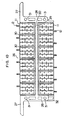
- a grid structure 11 made of synthetic resin but not having a part of an active material support rib cut off.
- the grid structure is formed by injection moulding of a pellet containing polypropylene as a main constituent and glass fibers mixed thereto by 30 weight %. Glass fibers each having a diameter of 12 pm and a short length of about 3 mm are used to enhance uniform distribution of the glass fibers in the pellet and reinforcement effect. Thanks to the inclusion of the glass fibers, the grid structure mainly containing polypropylene can be improved in its physical characteristics of both heat resistance properties and rigidity.
- a frame rib 13 has a portion which is integral with a connector lug 12.
- a longitudinal rib 14 and a lateral rib 15 define an active material support rib.
- the support rib is more slender and thinner than the surrounding frame rib 13.
- the frame rib 13 and the support rib constitute a grid rib structure which is a basic structure of the grid structure.
- Thermal deformation temperatures change with the amount of mixed glass fibers. While the thermal deformation temperature of polypropylene without glass fibers mixed is 95°C, polypropylene mixed with glass fibers by 30 weight % has a thermal deformation temperature of about 150°C which is sufficient to prevent the grid structure immersed in molten lead or lead alloy from being deformed.
- Polypropylene and glass fibers both have excellent acid resistance and oxidization resistance properties and have no adverse influence upon battery performances.
- molten lead is prepared by heating pure lead having a melting point of 327°C under temperature control to 332 ⁇ 2°C effected by on-off controlling a heat insulation heater.
- the grid structure 11 is immersed in the molten lead with the connector lug 12 faced downwards to coat a lead film 16 on the surface of the grid structure.
- the time for the immersion of the grid structure 11 in the molten lead corresponding to the time for the connector lug 12 to stay in the molten lead is accurately controlled to 0.3 ⁇ 0.02 seconds.
- the grid structure is cooled by blasting air thereto by means of a fan, thereby producing a grid for use in a lead storage battery which is coated with the lead film 16 to a thickness of 300 pm as shown in Fig. 2.
- the leadfilm 16 may be coated all over the grid structure, but the coating of the lead film over at least part of the grid rib structure including an upper portion of the frame rib 13 inclusive of the connector lug 12 and an upper portion of the active material support rib makes it possible to collect current from the paste active material filled in the subsequent process, and can enhance reduction of weight of the battery plate.
- Thickness of the lead film 16 can be controlled by adjusting the time for the grid structure 11 to be immersed in the molten lead, as shown in Fig. 11 which illustrates the correlation obtained when a 1.5 mm diameter rod of polypropylene is immersed in molten lead.
- Fig. 11 illustrates the correlation obtained when a 1.5 mm diameter rod of polypropylene is immersed in molten lead.
- the polypropylene rod is deformed by heating or the time for immersion is too short to coat the lead film on the surface of the polypropylene rod.
- the lead film by suitably controlling the temperature of the molten lead and maintaining the immersion time within a range between 0.05 and 1.05 seconds.
- a grid structure 11 of small grid mesh when the grid structure is immersed in the molten lead within the permissible range of immerse time as shown in Fig. 11 to the longest extent shown, not only a lead film 16 can be coated on the grid rib structure but also lead thin film 17 is sometimes formed because of a surface tension of the molten lead, clogging the grid mesh.
- part of the grid rib structure to be coated with lead exclusive of the frame rib but inclusive of part of either longitudinal ribs 14 or lateral ribs 15, both the longitudinal and lateral ribs constituting the active material support ribs is cut off as shown at 18 in Fig. 4 to partly open the grid mesh.
- the paste active material may continuously be filled in the grid mesh from one side of the grid through a wellknown roller filling method and subsequently it may be dried in a manner well known in the art.
- an upper portion of the grid rib structure inclusive of the connector lug 12 is coated with the lead film 16.
- the active material support rib consisting of the longitudinal ribs 14 and lateral ribs 15 is made more slender than the frame rib, but the slenderness does not vary from the portion to be coated with the lead film to the remaining portion not to be coated with the lead film.
- This construction permits, at any rate, the filling of the paste active material but for smooth filling of the active material and uniformity of the amount of active material filled, it is preferable that the portion coated with the lead film be flush with the remaining portion when the grid is completed.
- the grid rib structure constituting the grid structure 11 may be decreased in thickness and width at the portion to be coated with the lead film as shown in Fig. 6.
- the portion which is not to be coated with the lead film is designated by 19 and the portion to be coated with the lead film by 20. Since the portion 20 to be coated with the lead film is immersed in molten lead and subjected to heat during the immersion, it is made of polypropylene mixed with glass fibers so that it may have heat resistant properties and its thickness is varied to resist against thermal deformation.
- An uppermost portion 21 of the frame rib has a substantially circular cross-sectional area of 1.1 mm diameter when the portion 19 not coated with the lead film has a thickness of 1.7 mm and a width of 1.7 mm.
- a connector lug 12 integral with the uppermost portion 21 of the frame rib has then the same thickness as the diameter of the portion 21.
- Right and left portions 22 to be coated with the lead film which connect the uppermost portion 21 to right and left lower portions not to be coated with the lead film are each divided into an upper sub-portion 22a and a lower sub-portion 22b.
- the upper sub-portion 22a has the same diameter as the uppermost frame rib portion 21 and the lower sub-portion 22b has a thickness of 1.1 mm and a width of 1.4 mm with the outer side recessed relative to the frame rib portion 19 to form a shoulder 23 and with the inner side being flush with the frame rib portion 19. Consequently, the lower sub-portion 22b has substantially an elliptical cross-sectional area.
- a longitudinal rib 14 is more slender than the uppermost portion 21, and a lateral rib 15 has a cross-sectional size which is the same as or less than that of the longitudinal rib and is partly cut off as shown at 18 to assure steady coating of the lead film over the entire surface of the portion 20 to be coated.
- Illustrated in Fig. 7 is a grid which is produced by immersing the grid structure 11 having the portion 20 to be coated with the lead film in molten lead for 0.3 seconds, pulling it up and cooling it to coat the lead film designated by 16. As shown in Fig.
- the uppermost portion 21, connector lug 12 and right and left connecting portions 22 now coated with the lead film have the same cross-sectional size as that of the portion 19 and the shoulder 23 substantially disappears.
- the longitudinal and lateral ribs 14 and 15 of the active material support rib are also coated with the lead film but they have the original cross-sectional size which is more slender than that of the uppermost portion 21, so that the active material support rib can be more slender than the frame rib. Accordingly, the paste active material can be readily filled in the grid mesh and electrical conduction between the active materials and between the active material and the connector lug can be assured.
- the connector lug 12 After completion of the battery plate, the connector lug 12 is connected to a connector lug of the battery plate by welding or soldering. Therefore, the thickness of the lead film coated on the connector lug 12 should preferably be sufficiently large.
- front and rear surfaces of the connector lug 12 are formed with central longitudinal grooves 24 each having a depth of 0.2 mm and a width of 0.8 mm as shown in Fig. 8, thereby making easier the coating of lead on the grooves than on the remaining portion.
- a grid of Fig. 8 is also advantageous in that the portion not to be coated with the lead film, generally designated by 19, is improved in supporting the active material and electrical conduction between the active materials and between the active material and the connector lug can be improved.
- one of the longitudinal and lateral ribs constituting the active material support rib, lateral ribs 15 herein, are staggered within the region of the portion 19 so as to decrease the degree of partitioning of the active material by the lateral ribs and enhance electrical conduction between the active materials in the vertical direction of the battery plate.
- Cross-sectional area. configurations taken on lines A ⁇ A', B-B' and C-C' in Fig. 8 are shown at sections I, II and III in Fig. 9.
- the frame rib 11 in the portion 19 not to be coated with the lead film has substantially an L-shaped cross-sectional area with a shoulder 25, which cross-sectional area can assure steady support of the paste active material.
- a sheet or panel 26 as shown in Fig. 10 is produced having a number of grid structures 11 of Fig. 8 each serving as a unit battery plate, 12 grid structures herein constituting two arrays of an upper array of 6 grid structures and a lower array of 6 grid structures, each grid structure being formed by injection moulding of polypropylene mixed with glass fibers.
- Illustrated in Fig. 10 are right and left lugs 27 for suspension, and a frame rib 28 for providing the panel with rigidity and a central rib 29 between the upper and lower arrays which play an important role in preventing constrictive deformation which would occur when injection moulding and consequently obtaining highly accurate grid structures 11.
- the grid structures 11 are connected with each other and with the frame ribs 28 and central rib 29 by means of connecting bands 30. Holes 31 adapted for positioning in the course of the immersion of the panel of the grid structures 11 in the molten , lead fit on guide pins provided for an immersion tool.
- the panel 26 is first turned through 180° to take a posture inverted from that of Fig. 10 and the upper positioning holes are fitted on the guide . pins. Thereafter, a portion of the panel above line XX as viewed from Fig. 10, inclusive of connector lugs 12, is immersed in a bath of molten lead for 0.3 ⁇ 0.02 seconds and subsequently pulled up.
- the molten lead is controlled to a temperature of 332 ⁇ 2°C which is higher than the melting point described previously and its free surface is constantly maintained at a constant level and removed of flaking contaminants such as oxides.
- the panel is again turned through 180° to return to the posture shown in Fig. 10 and a portion of the panel below line Y-Y', inclusive of connector lugs 12, is then immersed in the bath of molten lead in a similar manner to coat the lead film.
- the grid structures in the form of the panel partly coated with the lead film is applied to a paste filling machine, by which the paste active material is pressed and filled into the grid mesh from one side of the panel. In this manner, 12 battery plates are completed. In the application of unformed battery plate, the battery plates are separated from each other at the connecting bands 30.
- the panel is dried after the filling of the paste active material and thereafter one frame rib, inclusive of a connecting band 32 for electrical conduction, on the left side with respect to line Z-Z' as viewed from Fig. 10 is immersed in the molten lead to set up a path for electrical connection of the upper and lower arrays.
- the panel is then subjected to formation process and the respective battery plates are subsequently separated by cutting at the connecting bands 30.
- the above production method for the united grid structure and battery plate can enhance mass production and efficiency of use of lead as well as dimensional accuracy of the battery plate.
- the grid structure may preferably be made of pure polypropylene or polyethylene in place of fiber-reinforced plastic type polypropylene.
- the grid structure thus made of synthetic resin or inorganic materials may be coated with the lead film or a lead alloy film whose coating can be controlled at lower temperatures than temperatures for the lead film.
- molten lead or lead alloy may directly be poured over the grid and, surplus molten lead or lead alloy may be collected by a pan or tank for re-utilization.
Landscapes
- Chemical & Material Sciences (AREA)
- Chemical Kinetics & Catalysis (AREA)
- Electrochemistry (AREA)
- General Chemical & Material Sciences (AREA)
- Cell Electrode Carriers And Collectors (AREA)
Claims (7)
dadurch gekennzeichnet, daß die Schicht auf die Anschlußlasche und zumindest auf einen an diese angrenzenden Bereich aufgebracht ist, wobei der Bereich einen Teil einer Rahmenrippe (13) und eine aktive Materialstützrippe (14, 15) umfaßt, die teilweise (18) weggebrochen ist.
Applications Claiming Priority (4)
| Application Number | Priority Date | Filing Date | Title |
|---|---|---|---|
| JP56157076A JPS5859560A (ja) | 1981-10-01 | 1981-10-01 | 鉛蓄電池用格子体 |
| JP157076/81 | 1981-10-01 | ||
| JP8360/82 | 1982-01-21 | ||
| JP57008360A JPS58126672A (ja) | 1982-01-21 | 1982-01-21 | 鉛蓄電池用格子体の製造法 |
Publications (2)
| Publication Number | Publication Date |
|---|---|
| EP0076626A1 EP0076626A1 (de) | 1983-04-13 |
| EP0076626B1 true EP0076626B1 (de) | 1986-07-30 |
Family
ID=26342867
Family Applications (1)
| Application Number | Title | Priority Date | Filing Date |
|---|---|---|---|
| EP82305133A Expired EP0076626B1 (de) | 1981-10-01 | 1982-09-29 | Gitter für Bleiakkumulator und Verfahren zu seiner Herstellung |
Country Status (3)
| Country | Link |
|---|---|
| US (1) | US4782585A (de) |
| EP (1) | EP0076626B1 (de) |
| DE (1) | DE3272337D1 (de) |
Families Citing this family (24)
| Publication number | Priority date | Publication date | Assignee | Title |
|---|---|---|---|---|
| DE3922424C2 (de) * | 1989-07-07 | 1994-02-03 | Hagen Batterie Ag | Elektrode für elektrochemische Zellen und Verfahren zur Herstellung einer Gitterplatte für eine Elektrode |
| US5401596A (en) * | 1991-10-14 | 1995-03-28 | Stoilov; Georgi T. | Hermetically sealed dry accumulator |
| US5332634A (en) * | 1992-10-13 | 1994-07-26 | Kamina, Ltd. | Method of making lead electrodes |
| DE4331446A1 (de) * | 1993-09-16 | 1995-03-23 | Vb Autobatterie Gmbh | Plattenblock für Bleiakkumulatoren |
| JPH10188996A (ja) | 1996-12-26 | 1998-07-21 | Matsushita Electric Ind Co Ltd | 鉛蓄電池用格子体 |
| US5858575A (en) * | 1997-05-30 | 1999-01-12 | General Motors Corporation | Hot dipped PB-CA grids for lead-acid batteries |
| US6274274B1 (en) * | 1999-07-09 | 2001-08-14 | Johnson Controls Technology Company | Modification of the shape/surface finish of battery grid wires to improve paste adhesion |
| US6953641B2 (en) * | 2001-01-05 | 2005-10-11 | Johnson Controls Technology Company | Battery grid |
| EP1771900A1 (de) * | 2004-06-25 | 2007-04-11 | György Andras Sarosi | Verfahren und anordnung zur herstellung eines gitters für eine bleibatterieplatte |
| EP2287948B1 (de) | 2005-05-23 | 2016-01-06 | Johnson Controls Techonology Company | Batteriegitter |
| US20080131774A1 (en) * | 2005-11-08 | 2008-06-05 | Yuichi Tsuboi | Negative Electrode Current Collector for Lead Storage Battery and Lead Storage Battery Including the Same |
| CN101669238B (zh) | 2007-03-02 | 2015-07-01 | 约翰逊控制技术公司 | 用于电池的负极板栅 |
| EP2313353B1 (de) * | 2008-06-09 | 2011-10-26 | Commissariat à l'Énergie Atomique et aux Énergies Alternatives | Verfahren zur herstellung einer elektrode für blei-säure-batterie |
| MX338843B (es) | 2010-03-03 | 2016-05-03 | Johnson Controls Tech Co | Rejillas de bateria y metodos para fabricar las mismas. |
| US9748578B2 (en) | 2010-04-14 | 2017-08-29 | Johnson Controls Technology Company | Battery and battery plate assembly |
| KR101951453B1 (ko) | 2010-04-14 | 2019-02-22 | 존슨 컨트롤스 테크놀러지 컴퍼니 | 배터리, 배터리 플레이트 조립체 및 조립 방법 |
| US9761883B2 (en) | 2011-11-03 | 2017-09-12 | Johnson Controls Technology Company | Battery grid with varied corrosion resistance |
| CN103931043B (zh) * | 2011-11-17 | 2015-05-20 | 松下电器产业株式会社 | 铅蓄电池 |
| DE202013012569U1 (de) | 2013-10-08 | 2017-07-17 | Johnson Controls Autobatterie Gmbh & Co. Kgaa | Gitteranordnung für eine plattenförmige Batterieelektrode eines elektrochemischen Akkumulators sowie Akkumulator |
| DE102013111667A1 (de) | 2013-10-23 | 2015-04-23 | Johnson Controls Autobatterie Gmbh & Co. Kgaa | Gitteranordnung für eine plattenförmige Batterieelektrode und Akkumulator |
| WO2015173781A1 (en) * | 2014-05-16 | 2015-11-19 | U Bat (Pty) Ltd | Electrical storage batteries |
| CN119315041A (zh) | 2017-01-27 | 2025-01-14 | Cps科技控股有限公司 | 电池板栅 |
| US20210206023A1 (en) * | 2017-06-29 | 2021-07-08 | Gc Corporation | Scale |
| CN110224142A (zh) * | 2019-07-03 | 2019-09-10 | 周诚悦 | 一种编网浇铸式铅酸电池阳极板栅及其制备方法 |
Family Cites Families (15)
| Publication number | Priority date | Publication date | Assignee | Title |
|---|---|---|---|---|
| US1509186A (en) * | 1922-08-16 | 1924-09-23 | Prest O Lite Co Inc | Storage cell, electrode therefor, and process of making the same |
| US2064324A (en) * | 1935-03-13 | 1936-12-15 | Western Electric Co | Electric storage battery |
| BE444320A (de) * | 1941-02-17 | |||
| DE746830C (de) * | 1941-07-23 | 1944-08-25 | Dr Med Max Riese | Elektrodenplatte fuer elektrische Sammler |
| GB689003A (en) * | 1951-03-05 | 1953-03-18 | Chloride Electrical Storage Co | Improvements in primary and secondary electric batteries |
| US2694099A (en) * | 1952-11-21 | 1954-11-09 | Gould National Batteries Inc | Lead-acid battery grid |
| US3275473A (en) * | 1964-01-03 | 1966-09-27 | Eagle Picher Co | Battery grid |
| US3269863A (en) * | 1965-07-02 | 1966-08-30 | Gen Motors Corp | Storage battery plate |
| FR1485262A (fr) * | 1965-07-02 | 1967-06-16 | Gen Motors Corp | Plaque pour batterie d'accumulateurs électriques et son procédé de fabrication |
| US3516864A (en) * | 1967-11-20 | 1970-06-23 | Gen Motors Corp | Battery grid and terminal therefor |
| US3516863A (en) * | 1968-01-22 | 1970-06-23 | Gen Motors Corp | Battery plate structure |
| US3813300A (en) * | 1970-02-12 | 1974-05-28 | Storage Battery Co Ltd | Paste-type electrode backing plate for lead-acid battery |
| GB1314891A (en) * | 1970-07-14 | 1973-04-26 | Ici Ltd | Grids for the electrodes of secondary cells and batteries |
| US3751288A (en) * | 1971-06-23 | 1973-08-07 | Dow Chemical Co | Solidifying a thin layer of metal on plastic film |
| US4121024A (en) * | 1977-11-10 | 1978-10-17 | The International Nickel Company, Inc. | Negative electrode for lead-acid storage battery |
-
1982
- 1982-09-28 US US06/425,256 patent/US4782585A/en not_active Expired - Lifetime
- 1982-09-29 EP EP82305133A patent/EP0076626B1/de not_active Expired
- 1982-09-29 DE DE8282305133T patent/DE3272337D1/de not_active Expired
Also Published As
| Publication number | Publication date |
|---|---|
| US4782585A (en) | 1988-11-08 |
| DE3272337D1 (en) | 1986-09-04 |
| EP0076626A1 (de) | 1983-04-13 |
Similar Documents
| Publication | Publication Date | Title |
|---|---|---|
| US4782585A (en) | Grid for lead storage battery and method for its production | |
| CA1081773A (en) | Composite article and method of manufacturing | |
| US6953641B2 (en) | Battery grid | |
| US4275130A (en) | Bipolar battery construction | |
| CA1327956C (en) | Method and apparatus for coating a core material with metal | |
| US4554228A (en) | Negative electrode for lead accumulators | |
| US6232017B1 (en) | Grid for lead acid battery | |
| EP0734084B1 (de) | Bleiakkumotor und Verfahren zu ihrer Herstellung | |
| US5344727A (en) | Bipolar battery electrode | |
| US20090246618A1 (en) | Insert molded electrode grid | |
| US3926674A (en) | Method of manufacturing electrical connection elements for supporting electrodes for storage cells | |
| US3516864A (en) | Battery grid and terminal therefor | |
| CN111682220A (zh) | 一种铅酸蓄电池用含碳材料轻量化板栅及其制备方法 | |
| EP0693752B1 (de) | Verfahren zur Anfertigung von Kernbrennstabbündelgittern, und mittels dadurch angefertige Gitter | |
| US5201924A (en) | Filling mat-immobilized-electrolyte batteries | |
| JPS5866266A (ja) | 鉛蓄電池極板用基体 | |
| KR100250381B1 (ko) | 축전지용 극판에 활물질을 지지하는 방법 및 그 축전지 | |
| WO2013106419A1 (en) | Improved substrate for electrode of electrochemical cell | |
| EP0014282A1 (de) | Ringförmige Elektrodestruktur und Verfahren zu deren Herstellung | |
| EP1755847B1 (de) | Herstellungsverfahren und vorrichtung zur verwendung in dem herstellungsverfahren | |
| GB1604607A (en) | Composite articles | |
| JPH0318306B2 (de) | ||
| CN221783243U (zh) | 极片结构及锂电池 | |
| JP3624583B2 (ja) | 密閉形鉛蓄電池用極板の製造方法 | |
| JP3648780B2 (ja) | 密閉形鉛蓄電池用集電体の製造方法 |
Legal Events
| Date | Code | Title | Description |
|---|---|---|---|
| PUAI | Public reference made under article 153(3) epc to a published international application that has entered the european phase |
Free format text: ORIGINAL CODE: 0009012 |
|
| AK | Designated contracting states |
Designated state(s): DE FR GB |
|
| 17P | Request for examination filed |
Effective date: 19830901 |
|
| GRAA | (expected) grant |
Free format text: ORIGINAL CODE: 0009210 |
|
| AK | Designated contracting states |
Kind code of ref document: B1 Designated state(s): DE FR GB |
|
| REF | Corresponds to: |
Ref document number: 3272337 Country of ref document: DE Date of ref document: 19860904 |
|
| ET | Fr: translation filed | ||
| PLBE | No opposition filed within time limit |
Free format text: ORIGINAL CODE: 0009261 |
|
| STAA | Information on the status of an ep patent application or granted ep patent |
Free format text: STATUS: NO OPPOSITION FILED WITHIN TIME LIMIT |
|
| 26N | No opposition filed | ||
| PGFP | Annual fee paid to national office [announced via postgrant information from national office to epo] |
Ref country code: FR Payment date: 19960910 Year of fee payment: 15 |
|
| REG | Reference to a national code |
Ref country code: GB Ref legal event code: 746 Effective date: 19960820 |
|
| PGFP | Annual fee paid to national office [announced via postgrant information from national office to epo] |
Ref country code: GB Payment date: 19960920 Year of fee payment: 15 |
|
| PGFP | Annual fee paid to national office [announced via postgrant information from national office to epo] |
Ref country code: DE Payment date: 19961004 Year of fee payment: 15 |
|
| PG25 | Lapsed in a contracting state [announced via postgrant information from national office to epo] |
Ref country code: GB Free format text: LAPSE BECAUSE OF NON-PAYMENT OF DUE FEES Effective date: 19970929 |
|
| PG25 | Lapsed in a contracting state [announced via postgrant information from national office to epo] |
Ref country code: FR Free format text: THE PATENT HAS BEEN ANNULLED BY A DECISION OF A NATIONAL AUTHORITY Effective date: 19970930 |
|
| GBPC | Gb: european patent ceased through non-payment of renewal fee |
Effective date: 19970929 |
|
| PG25 | Lapsed in a contracting state [announced via postgrant information from national office to epo] |
Ref country code: DE Free format text: LAPSE BECAUSE OF NON-PAYMENT OF DUE FEES Effective date: 19980603 |
|
| REG | Reference to a national code |
Ref country code: FR Ref legal event code: ST |