EP0075036B1 - Leistungshalbleiterbauelement für Flüssigkeitskühlung - Google Patents
Leistungshalbleiterbauelement für Flüssigkeitskühlung Download PDFInfo
- Publication number
- EP0075036B1 EP0075036B1 EP81107465A EP81107465A EP0075036B1 EP 0075036 B1 EP0075036 B1 EP 0075036B1 EP 81107465 A EP81107465 A EP 81107465A EP 81107465 A EP81107465 A EP 81107465A EP 0075036 B1 EP0075036 B1 EP 0075036B1
- Authority
- EP
- European Patent Office
- Prior art keywords
- cooling
- power semiconductor
- semiconductor component
- component according
- boxes
- Prior art date
- Legal status (The legal status is an assumption and is not a legal conclusion. Google has not performed a legal analysis and makes no representation as to the accuracy of the status listed.)
- Expired
Links
Images

Classifications
-
- H—ELECTRICITY
- H10—SEMICONDUCTOR DEVICES; ELECTRIC SOLID-STATE DEVICES NOT OTHERWISE PROVIDED FOR
- H10W—GENERIC PACKAGES, INTERCONNECTIONS, CONNECTORS OR OTHER CONSTRUCTIONAL DETAILS OF DEVICES COVERED BY CLASS H10
- H10W40/00—Arrangements for thermal protection or thermal control
- H10W40/40—Arrangements for thermal protection or thermal control involving heat exchange by flowing fluids
- H10W40/47—Arrangements for thermal protection or thermal control involving heat exchange by flowing fluids by flowing liquids, e.g. forced water cooling
Definitions
- the invention relates to a power semiconductor component for liquid cooling according to the preamble of claim 1.
- a water-cooled power semiconductor component consists of a disk cell with an insulating housing and with electrical and thermal contacting of the semiconductor wafer.
- Two cooling sockets through which liquid flows and which are arranged on both sides of the semiconductor wafer are pressed onto their two main surfaces and are integrated together with the semiconductor wafer into the electrically insulating, enlarged insulating housing provided with bushings for external electrical connections.
- the insulating housing has common external hydraulic connections for the supply and discharge of the coolant, to which the insulating housing is located on the inlet and outlet sides down and up and continues at the height of the cooling sockets, initially without connection with respect to the cooling sockets, with concentric duct bends in the central axis perpendicular to the plane of the pane connect an arc angle smaller than 90 ° and above and below in the opposite direction and then to the up and down leading duct parts, which follow concentric to the respective junction but not to the same connected duct arches, which ultimately follow the parallel and straight cooling duct sections are connected to the cooling sockets and are thus connected to one another.
- the invention is therefore based on the object of improving the electrical and thermal transmission from the semiconductor wafer to the further electrical cable or to the cooling socket in a power semiconductor component for liquid cooling of the type mentioned at the outset, wherein a disc cell type without positive contacting is to be used.
- Multi-contacts are known per se from DE-A-2 855 493, DE-A-29 37 049 and DE-A-29 38 095.
- the multi-contacts are surrounded by the coolant, while in the first two documents the power semiconductor component is hermetically sealed with the aid of its own housing.
- a detailed embodiment of such a component, especially for liquid cooling with a non-insulating cooling medium, is not described in any of the cited documents.
- WO-79/01012 already describes a power semiconductor component for liquid cooling, the two main electrodes of the semiconductor wafer being contacted by means of thermally and electrically conductive multi-contacts, and the semiconductor wafer with its contacts being accommodated in a housing hermetically sealed against the coolant.
- the electrical connection is made to the outer walls of the cooling boxes, so that their electrical resistance causes an additional power loss.
- the advantages that can be achieved with the invention are, for. B. in that there is no non-positive contact and therefore the relative movements occurring when the element is heated in operation due to different expansion coefficients of the cohesively connected parts can no longer impair the alternating load strength of the elements.
- the thermal resistance of the component is also advantageously low.
- the proposed housing structure relieves the push-fit connection by pushing and pulling.
- the component is particularly suitable as a single component of a block composed of many similar power semiconductor components, the accessibility to the individual components being very good (important for the exchange of defective components)
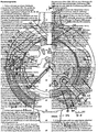
- Fig. 1 the power semiconductor device is shown in elevation in two sections A-B and A-C. The respective section lines A, B and C are shown in FIG. 2.
- a located inside the power semiconductor device is integrally connected to multi-contacts 2 (multi-spring contacts) via each of its two main electrodes. These multi-contacts 2 are each connected to a cooling socket 3.
- the cooling sockets 3 consist of a base 4, on which cooling rods 5 and an electrical connection eye 5 with an internal thread 7 for the electrical connection of the power semiconductor component are formed.
- the cooling sockets 3 also have a wall 8 with two openings 9 and a materially attached cover 10.
- a groove 11 is made in the bottom 4 of the cooling sockets 3.
- the power semiconductor component is designed as a thyristor, a gate connecting line 19 is inserted into the groove 11.
- the bottom 4 of the cooling boxes 3 has a recess 12, to which a membrane 13 is firmly bonded.
- a housing e.g. made of a thermoplastic material, in the form of two mirror-image half-shells 20 pushed over the already assembled assembly and attached to the cooling boxes 3.
- the half-shells 20 consist of a wall 21, each with a rim 22 and 23 which extends inwards and downwards and a hydraulic connecting eye 24 which projects outwards.
- the "upper" part of the power semiconductor component is the one in FIG. 1 to the left of the semiconductor crystal wafer 1 arranged part referred to as the "lower" part of the part arranged to the right of the semiconductor crystal wafer.
- a bore 25 is provided with an internal thread for connecting a hydraulic coolant line.
- a channel 26 extends upwards from the bore 25 and opens into a channel 27 (see FIG. 2). This leads over a quarter circle to a downward channel 28 (see FIG. 2) which in turn opens into a channel 29. This leads back by the same angular path to an opening 30 of a spout 31 projecting inward into the opening 9 of the lower cooling box 3.
- a similar liquid path leads downward from the bore 25 via a channel 32, a channel 33, a channel 34 (see FIG. 2 in this regard), a channel 35 and an opening 36 of a spout 37, which leads into an opening 9 of the upper cooling box 3 protrudes.
- Cooling cans 3 is made by round cord rings 38.
- the channels 27/29 (see FIG. 2) and 33/35 (see FIG. 2) are made into tight channels by applying two semicircular perforated disks 39 made of insulating material to the shelves 22/23 and connecting them integrally. With the perforated disks 39, the cooling sockets 3 are also insulated, except for the electrical connecting eyes 6.
- the described channel routing achieves a line length that allows water to be used as a coolant despite the large reverse voltage on the power semiconductor component.
- the two cooling sockets 3 of the power semiconductor component are supplied with cooling liquid via the hydraulic connecting eye 24, i.e. coolant is led into the interior of the cooler can.
- the dissipation of the cooling liquid heated by the heat loss of the semiconductor crystal wafer 1 takes place in the same way via channels, troughs and openings of the same construction, not shown, to the second hydraulic connection 24.
- the heat is transported from the heated semiconductor crystal wafer 1 via the multi-contacts 2 to the cooling box base 4 and to the cooling sticks 5.
- the cooling can lid 10 is also heated via the cooling can sticks 5 and the cooling can wall 8.
- the cooling liquid flows around the cooling rods 5 and also acts on the bottom 4, the wall 8 and the cover 10 of the cooling box 3.
- the cooling liquid does not act directly on the multi-contacts 2, since these are sealed off from the cooling liquid by the bottom of the cooling box, the membranes 13, the collar 15 and the ceramic ring 14.
- the half-shells 20 are fastened to the cooling box 3 by means of several screws 40 with securing elements 41.
- eyes 42 projecting inwards are attached to the wall 21 of the half-shells 20.
- a cathode auxiliary connection is expediently also brought out in addition to the gate connection. This is done by means of a rod 43 which is integrally connected to the cooling socket 3 and penetrates the wall 21 of the semiconductor shell 20 and on which a tab 44 is applied.
- Gate and cathode connections are led outwards at the separation points of the two half-shells 20, for which purpose a recess 45 and two semicircular recesses 46/47 are made.
- an opening 48 in the Half-shell 20 in the region of the recess 45 injected a closed-pore insulating filler 49.
- An opening, not shown, diametrically opposite the opening 48 allows the air to escape during the filling process and enables control of the filling state of the substance 49.
- Fig. 2 the power semiconductor component is shown in plan in two sections D-E and D-F.
- the respective section lines D, E and F are shown in FIG. 1.
- the channel guide bore 25 of the hydraulic connecting eye 24 - upper channel 26 - upper channel 27 - channel 28 downward - lower channel 29 and the channel guide lower channel 33 - channel 34 upward - upper channel 35 - upper opening 36 the spout 37 can be seen.
- cooling rods 5 and the wall 8 of the cooling sockets 3 are shown. Furthermore, the cooling rods 5 and the wall 8 of the cooling sockets 3, the screw 40 with securing element 41 penetrating the eye 42 of the half-shell 20, the gate connecting line 19 with pump connector 16, spacer tubes 17 and the electrical plug pins 18, the wall 21 with recess 45 , the ceramic ring 14, the cord rings 38 and the filler 49 are shown.
Landscapes
- Cooling Or The Like Of Semiconductors Or Solid State Devices (AREA)
- Cooling Or The Like Of Electrical Apparatus (AREA)
Priority Applications (4)
| Application Number | Priority Date | Filing Date | Title |
|---|---|---|---|
| DE8181107465T DE3175489D1 (en) | 1981-09-19 | 1981-09-19 | Semiconductor power device with fluid cooling |
| EP81107465A EP0075036B1 (de) | 1981-09-19 | 1981-09-19 | Leistungshalbleiterbauelement für Flüssigkeitskühlung |
| JP57162085A JPS5863154A (ja) | 1981-09-19 | 1982-09-17 | 液冷式電力用半導体素子 |
| US06/419,832 US4521170A (en) | 1981-09-19 | 1982-09-17 | Power semiconductor component for liquid cooling |
Applications Claiming Priority (1)
| Application Number | Priority Date | Filing Date | Title |
|---|---|---|---|
| EP81107465A EP0075036B1 (de) | 1981-09-19 | 1981-09-19 | Leistungshalbleiterbauelement für Flüssigkeitskühlung |
Publications (2)
| Publication Number | Publication Date |
|---|---|
| EP0075036A1 EP0075036A1 (de) | 1983-03-30 |
| EP0075036B1 true EP0075036B1 (de) | 1986-10-15 |
Family
ID=8187921
Family Applications (1)
| Application Number | Title | Priority Date | Filing Date |
|---|---|---|---|
| EP81107465A Expired EP0075036B1 (de) | 1981-09-19 | 1981-09-19 | Leistungshalbleiterbauelement für Flüssigkeitskühlung |
Country Status (4)
| Country | Link |
|---|---|
| US (1) | US4521170A (enExample) |
| EP (1) | EP0075036B1 (enExample) |
| JP (1) | JPS5863154A (enExample) |
| DE (1) | DE3175489D1 (enExample) |
Families Citing this family (7)
| Publication number | Priority date | Publication date | Assignee | Title |
|---|---|---|---|---|
| DE3137407A1 (de) * | 1981-09-19 | 1983-04-07 | BBC Aktiengesellschaft Brown, Boveri & Cie., 5401 Baden, Aargau | Leistungshalbleiterbauelement fuer siedekuehlung |
| JPS61120468A (ja) * | 1984-11-16 | 1986-06-07 | Hitachi Ltd | 光半導体装置 |
| DE4101205A1 (de) * | 1990-02-09 | 1991-08-14 | Asea Brown Boveri | Gekuehltes hochleistungshalbleiterbauelement |
| DE19625755A1 (de) * | 1996-06-27 | 1998-01-02 | Bosch Gmbh Robert | Verbindungselement |
| US5983997A (en) * | 1996-10-17 | 1999-11-16 | Brazonics, Inc. | Cold plate having uniform pressure drop and uniform flow rate |
| US6729383B1 (en) | 1999-12-16 | 2004-05-04 | The United States Of America As Represented By The Secretary Of The Navy | Fluid-cooled heat sink with turbulence-enhancing support pins |
| CN119920698B (zh) * | 2025-03-27 | 2025-05-30 | 北京怀柔实验室 | 用于功率半导体器件的封装方法与封装的功率半导体器件 |
Citations (1)
| Publication number | Priority date | Publication date | Assignee | Title |
|---|---|---|---|---|
| DE2951521A1 (de) * | 1978-12-22 | 1980-06-26 | Rca Corp | Fluessigkeitsgekuehlte halbleitereinrichtung |
Family Cites Families (8)
| Publication number | Priority date | Publication date | Assignee | Title |
|---|---|---|---|---|
| US3654528A (en) * | 1970-08-03 | 1972-04-04 | Gen Electric | Cooling scheme for a high-current semiconductor device employing electromagnetically-pumped liquid metal for heat and current transfer |
| DE2160302C3 (de) * | 1971-12-04 | 1975-07-17 | Siemens Ag | Kühldose zum Einbau in Scheibenzellenstapel |
| DE2716066A1 (de) * | 1977-02-10 | 1978-10-12 | Bbc Brown Boveri & Cie | Fluessigkeitsgekuehltes leistungs- halbleiterbauelement in scheibenzellenbauweise, insbesondere mit wasserkuehlung |
| DE2705476A1 (de) * | 1977-02-10 | 1978-08-17 | Bbc Brown Boveri & Cie | Fluessigkeitsgekuehltes leistungs-halbleiterbauelement in scheibenzellenbauweise |
| US4188996A (en) * | 1977-05-04 | 1980-02-19 | Ckd Praha, Oborovy Podnik | Liquid cooler for semiconductor power elements |
| US4392153A (en) * | 1978-05-01 | 1983-07-05 | General Electric Company | Cooled semiconductor power module including structured strain buffers without dry interfaces |
| US4246660A (en) * | 1978-12-26 | 1981-01-27 | Queen's University At Kingston | Artificial ligament |
| DE2926342C2 (de) * | 1979-06-29 | 1982-10-28 | Siemens AG, 1000 Berlin und 8000 München | Kühldose für scheibenförmige Halbleiterbauelemente |
-
1981
- 1981-09-19 EP EP81107465A patent/EP0075036B1/de not_active Expired
- 1981-09-19 DE DE8181107465T patent/DE3175489D1/de not_active Expired
-
1982
- 1982-09-17 US US06/419,832 patent/US4521170A/en not_active Expired - Fee Related
- 1982-09-17 JP JP57162085A patent/JPS5863154A/ja active Granted
Patent Citations (1)
| Publication number | Priority date | Publication date | Assignee | Title |
|---|---|---|---|---|
| DE2951521A1 (de) * | 1978-12-22 | 1980-06-26 | Rca Corp | Fluessigkeitsgekuehlte halbleitereinrichtung |
Also Published As
| Publication number | Publication date |
|---|---|
| JPS633459B2 (enExample) | 1988-01-23 |
| US4521170A (en) | 1985-06-04 |
| EP0075036A1 (de) | 1983-03-30 |
| DE3175489D1 (en) | 1986-11-20 |
| JPS5863154A (ja) | 1983-04-14 |
Similar Documents
| Publication | Publication Date | Title |
|---|---|---|
| DE2317853C2 (de) | Elektrische Durchführung | |
| DE1923436C3 (de) | Vorrichtung zur Behandlung von flüssigen oder gasförmigen Medien in einem elektrostatischen Feld | |
| DE1589808C3 (de) | Vorrichtung zur Materialverformung durch magnetische Kräfte | |
| DE2137164A1 (de) | Halbleitervorrichtung fur Hochleistung mit Kuhlsystem | |
| EP3605762A1 (de) | Anordnung mit einer stromschienenvorrichtung und einem stromrichtergehäuse sowie verfahren zu deren herstellung, stromrichter für ein fahrzeug und fahrzeug | |
| DE102004025616A1 (de) | Halbleiterbauteil mit Kühlsystem | |
| DE102018202128A1 (de) | Elektrische Verbindungseinheit und Batteriesystem | |
| DE2160302B2 (de) | Kühldose zum Einbau in Scheibenzellenstapel | |
| WO2021099190A1 (de) | Kühlsystem und bauteil für eine elektrische maschine mit hohlleiterkühlung | |
| EP0075036B1 (de) | Leistungshalbleiterbauelement für Flüssigkeitskühlung | |
| WO2021001093A1 (de) | Aktiv gekühltes ladesteckverbinderteil | |
| DE4017749A1 (de) | Fluessigkeitskuehlkoerper aus elektrisch isolierendem material | |
| WO1993006605A1 (de) | Flüssigkeitsgekühlter hochlastwiderstand | |
| DE2855493A1 (de) | Leistungs-halbleiterbauelement | |
| EP2256753B1 (de) | Stromleiter für eine Hochstromdurchführung | |
| DE2740630C2 (de) | Hochstrom-Gleichrichteranordnung | |
| DE3112432A1 (de) | Vakuum-schaltkreistrenner | |
| DE4319682A1 (de) | Isolator mit internem Verbindungskanal | |
| DE19622667A1 (de) | Zündvorrichtung für einen Verbrennungsmotor und zugehöriges Herstellungsverfahren | |
| EP0124695A1 (de) | Klemme und Muffe für eine derartige Klemme | |
| DE2705476A1 (de) | Fluessigkeitsgekuehltes leistungs-halbleiterbauelement in scheibenzellenbauweise | |
| EP0459326A1 (de) | Flüssigkeitsgekühlte Drosselspule | |
| EP0073423B1 (de) | Verbindungselement für vollfeststoffisolierte Stromleiter | |
| DE3338165C2 (de) | Halbleiterbaueinheit mit Halbleiterbauelementen und Montage- und Kühlvorrichtung | |
| DE2641032C2 (de) | Stromrichtermodul |
Legal Events
| Date | Code | Title | Description |
|---|---|---|---|
| PUAI | Public reference made under article 153(3) epc to a published international application that has entered the european phase |
Free format text: ORIGINAL CODE: 0009012 |
|
| AK | Designated contracting states |
Designated state(s): CH DE FR GB IT LI SE |
|
| 17P | Request for examination filed |
Effective date: 19830830 |
|
| GRAA | (expected) grant |
Free format text: ORIGINAL CODE: 0009210 |
|
| AK | Designated contracting states |
Kind code of ref document: B1 Designated state(s): CH DE FR GB IT LI SE |
|
| ITF | It: translation for a ep patent filed | ||
| REF | Corresponds to: |
Ref document number: 3175489 Country of ref document: DE Date of ref document: 19861120 |
|
| ET | Fr: translation filed | ||
| PLBE | No opposition filed within time limit |
Free format text: ORIGINAL CODE: 0009261 |
|
| STAA | Information on the status of an ep patent application or granted ep patent |
Free format text: STATUS: NO OPPOSITION FILED WITHIN TIME LIMIT |
|
| 26N | No opposition filed | ||
| PG25 | Lapsed in a contracting state [announced via postgrant information from national office to epo] |
Ref country code: GB Effective date: 19890919 |
|
| PG25 | Lapsed in a contracting state [announced via postgrant information from national office to epo] |
Ref country code: SE Effective date: 19890920 |
|
| PG25 | Lapsed in a contracting state [announced via postgrant information from national office to epo] |
Ref country code: LI Effective date: 19890930 Ref country code: CH Effective date: 19890930 |
|
| GBPC | Gb: european patent ceased through non-payment of renewal fee | ||
| PG25 | Lapsed in a contracting state [announced via postgrant information from national office to epo] |
Ref country code: FR Effective date: 19900531 |
|
| REG | Reference to a national code |
Ref country code: CH Ref legal event code: PL |
|
| PG25 | Lapsed in a contracting state [announced via postgrant information from national office to epo] |
Ref country code: DE Effective date: 19900601 |
|
| REG | Reference to a national code |
Ref country code: FR Ref legal event code: ST |
|
| EUG | Se: european patent has lapsed |
Ref document number: 81107465.7 Effective date: 19900521 |