EP0074360B1 - Method for regulating a sorption heat pump - Google Patents
Method for regulating a sorption heat pump Download PDFInfo
- Publication number
- EP0074360B1 EP0074360B1 EP82900629A EP82900629A EP0074360B1 EP 0074360 B1 EP0074360 B1 EP 0074360B1 EP 82900629 A EP82900629 A EP 82900629A EP 82900629 A EP82900629 A EP 82900629A EP 0074360 B1 EP0074360 B1 EP 0074360B1
- Authority
- EP
- European Patent Office
- Prior art keywords
- heat pump
- consumer
- heat
- condenser
- temperature
- Prior art date
- Legal status (The legal status is an assumption and is not a legal conclusion. Google has not performed a legal analysis and makes no representation as to the accuracy of the status listed.)
- Expired
Links
Images
Classifications
-
- F—MECHANICAL ENGINEERING; LIGHTING; HEATING; WEAPONS; BLASTING
- F25—REFRIGERATION OR COOLING; COMBINED HEATING AND REFRIGERATION SYSTEMS; HEAT PUMP SYSTEMS; MANUFACTURE OR STORAGE OF ICE; LIQUEFACTION SOLIDIFICATION OF GASES
- F25B—REFRIGERATION MACHINES, PLANTS OR SYSTEMS; COMBINED HEATING AND REFRIGERATION SYSTEMS; HEAT PUMP SYSTEMS
- F25B30/00—Heat pumps
- F25B30/04—Heat pumps of the sorption type
-
- F—MECHANICAL ENGINEERING; LIGHTING; HEATING; WEAPONS; BLASTING
- F25—REFRIGERATION OR COOLING; COMBINED HEATING AND REFRIGERATION SYSTEMS; HEAT PUMP SYSTEMS; MANUFACTURE OR STORAGE OF ICE; LIQUEFACTION SOLIDIFICATION OF GASES
- F25B—REFRIGERATION MACHINES, PLANTS OR SYSTEMS; COMBINED HEATING AND REFRIGERATION SYSTEMS; HEAT PUMP SYSTEMS
- F25B49/00—Arrangement or mounting of control or safety devices
- F25B49/04—Arrangement or mounting of control or safety devices for sorption type machines, plants or systems
- F25B49/043—Operating continuously
-
- Y—GENERAL TAGGING OF NEW TECHNOLOGICAL DEVELOPMENTS; GENERAL TAGGING OF CROSS-SECTIONAL TECHNOLOGIES SPANNING OVER SEVERAL SECTIONS OF THE IPC; TECHNICAL SUBJECTS COVERED BY FORMER USPC CROSS-REFERENCE ART COLLECTIONS [XRACs] AND DIGESTS
- Y02—TECHNOLOGIES OR APPLICATIONS FOR MITIGATION OR ADAPTATION AGAINST CLIMATE CHANGE
- Y02A—TECHNOLOGIES FOR ADAPTATION TO CLIMATE CHANGE
- Y02A40/00—Adaptation technologies in agriculture, forestry, livestock or agroalimentary production
- Y02A40/90—Adaptation technologies in agriculture, forestry, livestock or agroalimentary production in food processing or handling, e.g. food conservation
- Y02A40/963—Off-grid food refrigeration
Definitions
- the present invention relates to a method for controlling a sorption heat pump according to the first part of claim 1 or 2.
- Sorption heat pumps of this type whether absorption or absorption heat pumps, are being used to an increasing extent for heating residential buildings.
- these heat pumps are intended to replace circulating water heaters or boilers as heat sources.
- the consumers of such heat pumps usually consist of underfloor, radiator or convector heaters, usually equipped with thermostatic valves, and domestic hot water tanks.
- an absorption heat pump with a fuel-heated expeller has become known from DE-A-2 838 715, in which the primary line of the heat exchanger of the temperature changer is checked by a bypass line, the throughput of which is controlled by a valve according to that of a sensor for the outside temperature . If the flow temperature of the heating circuit containing the radiators can be lowered due to lower heat requirements, this is usually a result of rising outside temperatures. This rising outside temperature causes the temperature sensor to suddenly change over the associated three-way reversing valve, as a result of which the heat exchanger of the temperature change is deactivated. The highly heated, poor solution thus comes directly to the expansion valve, which means that the last heating stage for the consumer fails. Thus, in the absence i is blingigke the outdoor temperature t consumers flow temperature in two stages controlled.
- the present invention is based on the object of specifying a control method for a sorption heat pump which, depending on the consumer heat requirement, minimizes the feed of primary energy into the expeller and at the same time ensures a sufficient throughput of solvent and refrigerant in order to optimize the internal circuit of the heat pump .
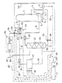
- the figure of the drawing represents a schematic diagram of an absorption heat pump.
- An expeller or cooker 1 with a rectifier which may be connected downstream is filled to a level 2 with a rich solution 3 consisting of ammonia vapor dissolved in water and is heated by a gas burner 4 which is fed via a gas line 6 provided with a solenoid valve 5.
- the rich solution is fed to the expeller 1 via a return line 7; under the action of the primary energy of the burner 4, the rich solution is separated into poor solution and refrigerant vapor, the poor solution being discharged via a line 8 and the refrigerant vapor via a line 9.
- the high-pressure part of the sorption heat pump is monitored by a pressure sensor 10, which according to a variant of the invention can also be a temperature sensor.
- This pressure sensor 10 can be arranged anywhere in the high-pressure part of the sorption heat pump, that is, also in the condenser.
- the high pressure part ranges from solvent to refrigerant expansion valve under on end of cooker and condenser.
- the sensor 10 is connected to a controller 12 via a measuring line 11.
- a temperature sensor could be arranged in the cooker or in the condenser or the line between the two.
- the refrigerant vapor line 9 leads to a condenser 13, which is designed as a heat exchanger and is penetrated by a coil 14. Downstream of the condenser 13, the line 9 continues and leads to an expansion valve 15, the output of which is connected to an evaporator 17 via a line 16. The evaporator is exposed in a known manner to an environmental energy source 18, for example air.
- a refrigerant & medium vapor line 19 leads from the evaporator to an absorber 20, the interior of which is also connected to line 8 with the interposition of a further expansion valve 21 for the poor solution.
- a pipe coil 22 passes through the interior of the absorber, so that the absorber acts as a heat exchanger.
- the line 7 provided with a circulation pump 23 is connected to the outlet of the absorber.
- a pipe 29 leads from the pipe coil 14 to the pipe coil 22 of the absorber 20, to which a flow line 31 leading to the consumer 24 and provided with a temperature sensor 30 leads, the temperature sensor 30 being connected to the controller 12 via a measuring line 32.
- the fuel solenoid valve 5 is connected to the output of the controller via a line 33, the pump 23 has a motor 34 which is also connected to the output of the controller 12 via a line 35.
- a controller 36 is assigned to the controller 12 via a line 36, to which an outside temperature sensor 38 is connected.
- the control method has the following functions: For the mode of operation, it is initially assumed that the outside temperature is constant, i.e. the temperature sensor 38 outputs the same or almost the same measured value, and the temperature TO of the environmental energy source 18 is also constant, so that the Evaporator 17 receives the same amount of energy in the unit of time.
- the consumer in particular in the case of thermostatic valve-controlled radiators, will also have the same heat requirement.
- This heat requirement can be determined from the level of the return temperature, which is given to the controller 12 via the return temperature sensor 27 or the measuring line 28.
- the flow temperature can also be used for this, which is available to the controller 12 via the temperature sensor 30 or the measuring line 32.
- the position of a mixing valve or the throughput could also be detected here, for example by switching a signal which is dependent on the pump speed of the circulating pump 25 to the controller 12.
- the consumer 24 will withdraw a certain heat output from the refrigerant circuit of the sorption heat pump via the heat exchangers 14 or 22.
- This heat output essentially depends on the outside temperature and the location of the heat pump. whereby one can use the so-called climate zones, into which the territory of the Federal Republic of Germany or at locations in other countries are divided.
- a heating curve can thus be predefined for the setpoint generator 37 of the controller, that is to say a specific heat requirement for the consumer, expressed in values of the flow or return temperature or the difference between the two, which normally corresponds approximately to the needs of the consumer.
- the setpoint value of the pressure or the temperature in the high-pressure part of the heat pump is thus dependent on the operating location and the outside temperature. It continues to be managed variably according to the type and, if necessary, change of the heating system. Taking these criteria into account, it is therefore obvious that, with a certain power consumption in the evaporator 17, the expeller or cooker 1 must be supplied with a certain amount of energy in the time unit via the burner 4 in order to maintain the heat balance of the refrigerant circuit of the heat pump. Likewise, the motor 34 of the solvent circulation pump 23 must be set accordingly in order to ensure the solution circulation corresponding to the heat balance.
- the controller 12 has proportional - or proportional - integral behavior.
- Proportional behavior could be achieved in the area of the fuel valve 5 by continuously opening and closing the valve depending on the control deviation or on increasing the voltage of the solvent pump motor 34.
- Integral prevention could be achieved if the fuel valve 5 is assigned a servomotor which starts to run when a control deviation occurs and makes an adjustment as long as the control deviation is present.
- Integral behavior for the actuating movement of the motor 34 could be achieved, for example, via a control transformer assigned to the solvent pump motor 34, the wiper of which is actuated by a motor which likewise starts at a constant speed when the control deviation occurs and only comes to rest when the control deviation approaches zero.
- At least one disturbance in the form of the consumer acts on the control circuit - condenser pressure - or temperature sensor, controller 12 and actuators 5 or 23: namely, the consumer changes his heat requirement, for example by opening one or more thermostatic valves or closing them or by additional ones Heat demand from the domestic hot water tank, the condenser pressure or the condenser temperature will decrease or vice versa with increased heat demand.
- This disturbance variable is immediately detected via the sensors 27 and 30 and sent to the controller 12.
- thermostatic valve-controlled consumers an increased heat requirement means a larger passage cross section in front of the radiator and thus a greater throughput through the radiator or radiators. The consequence of this is a reduced temperature difference between the flow and return.
- an increased heat requirement leads to a control deviation, since the increased heat requirement causes a decrease in the condenser pressure or the condenser temperature.
- the control deviation is counteracted by detecting the disturbance variable in advance by increasing the burner output by opening the solenoid valve 5 further.
- the result of this adjustment movement is an increased energy supply to the cooker, which results in an increase in the condenser pressure or the condenser temperature.
- the gradient of the rise or the condenser temperature is pressed onto the controller via the sensor 11, and when the control deviation approaches the zero value or when the zero value is exceeded, the throughput of the solvent pump 23 is also adjusted in the direction of increased throughput, for example by the motor 34 in its speed is increased.
- the control with disturbance variable control just described could also be assigned analogously to the evaporator.
- a change in the power consumed by the evaporator (falling outside temperature TO) has the same effect as an increased heat demand from the consumer.
- the evaporator temperature could be measured via a temperature sensor assigned to the evaporator and indirectly the heat output absorbed by the evaporator could be determined. This heat output would then be the disturbance variable that is applied to the controller.
- a valve could be provided in the refrigerant line to the expansion valve, which is opened and closed in a pulse-pause ratio, the pulse-pause ratio dictating the refrigerant vapor throughput.
Abstract
Description
Die vorliegende Erfindung bezieht sich auf ein Verfahren zum Regeln einer Sorptionswärmepumpe gemäß dem ersten Teil des Anspruchs 1 oder 2.The present invention relates to a method for controlling a sorption heat pump according to the first part of
Solche Sorptionswärmepumpen, seien es Absorptions- oder Resorptionswärmepumpen, werden in zunehmendem Maße zur Beheizung von Wohnhäusern eingesetzt. Hier sollen diese Wärmepumpen Umlaufwasserheizer oder Kessel als Wärmequellen ersetzen. Die Verbraucher solcher Wärmepumpen bestehen in der Regel aus Fußboden-, Radiatoren- oder Konvektorenheizungen, in der Regel mit Thermostatventilen ausgerüstet, und Brauchwasserspeichern.Sorption heat pumps of this type, whether absorption or absorption heat pumps, are being used to an increasing extent for heating residential buildings. Here, these heat pumps are intended to replace circulating water heaters or boilers as heat sources. The consumers of such heat pumps usually consist of underfloor, radiator or convector heaters, usually equipped with thermostatic valves, and domestic hot water tanks.
Aus der EP-A-1 858 Ist ein Heizverfahren mit einer bivalenten Wärmepumpe zum Heizen von Gebäuden bekanntgeworden, bei dem oberhalb einer bestimmten Temperaturschwelle die Heizanlage als Wärmepumpe arbeitet, während sie bei Unterschreiten der Temperaturgrenzschwelle als Kessel arbeitet. Im letzteren Falle wird der gesamte Vorrat an Absorptionsflüssigkeit in einem AbsorptionsgefäB gespeichert. Hierzu ist ein Außentemperaturfühler vorgesehen, dessen Signale zur Aufrechterhaltung eines bestimmten Temperatumiveaus auf ein Gasventil des Brenners wirken. Der Außentemperaturfühler erfasst somit nicht eine Änderung des Verbraucherverhattens. Weiterhin ist ein Druckfühler im Austreiber vorgesehen, der aber nicht zu einer Druckregelung dient, sondern lediglich zum Überwachen des Kesselbetriebes, da bei Ansteigen eines vom Druckgeber gemessenen Drucks ein Absperrventil geschlossen wird, sodaß die Flüssigkeitszufuhr zum Austreiber unterbrochen wird. Diese Betriebsweise tritt nicht im Wärmepumpenbetrieb auf. Weiterhin ist ein dritter Druckfühler vorhanden, der dem Verdampfer zu= geordnet ist und den in ihm herrschenden Druck abfühlt.From EP-A-1 858 a heating method with a bivalent heat pump for heating buildings has become known, in which the heating system works as a heat pump above a certain temperature threshold, while it operates as a boiler when the temperature limit falls below. In the latter case, the entire supply of absorption liquid is stored in an absorption vessel. To this end, an outside temperature sensor is provided, the signals act to maintain a certain Temperatum i veaus on a gas valve of the burner. The outside temperature sensor therefore does not detect a change in consumer behavior. Furthermore, a pressure sensor is provided in the expeller, which is not used for pressure control, but only for monitoring the boiler operation, since a shut-off valve is closed when a pressure measured by the pressure transmitter rises, so that the liquid supply to the expeller is interrupted. This mode of operation does not occur in heat pump operation. There is also a third pressure sensor, which is assigned to the evaporator and senses the pressure in it.
Aus der DE-B-1 021 389 ist ein Verfahren und eine Vorrichtung zum Betrieb einer kontinuierlich wirkenden Absorptionskältemaschine bekanntgeworden, bei der beim Anfahren der Kältemaschine die Zuleitung zum Kondensator so lange gesperrt ist, bis im Austreiber die zum kontinuierlichen Betrieb erforderlichen Druck- und Temperaturverhältnisse erreicht sind. Hier handelt es sich demgemäß um eine Anfahrsteuerung und nicht um eine Druckbeziehungsweise Temperaturregelung im Hochdruckteil der Wärmepumpe.From DE-B-1 021 389 a method and a device for operating a continuously operating absorption refrigerator are known, in which the supply line to the condenser is blocked until the chiller starts up the pressure and temperature conditions required for continuous operation are reached. Accordingly, this is a start-up control and not a pressure or temperature control in the high-pressure part of the heat pump.
Aus der US-A-2 272 871 ist eine Absorptionswärmepumpe bekanntgeworden, deren Austreiber nicht von einem Brenner, sondern mit Dampf beheizt wird. Den Verbraucher zu der US-Patentschrift bildet eine Luftheizung. Die eine Wärmeanforderung durch den Verbraucher kann bei dieser Art Wärmepumpe nicht erfasst werden.From US-A-2 272 871 an absorption heat pump has become known, the expeller of which is heated by steam rather than by a burner. Air heating is the consumer of the US patent. The one heat request by the consumer cannot be recorded with this type of heat pump.
Schließlich ist aus der DE-A-2 838 715 eine Absorptionswärmepumpe mit einem brennstoffbeheizten Austreiber bekannt geworden, bei der die Primärleitung des Wärmetauschers des Temperaturwechslers von einer Bypassleitung überprüft ist, deren Durchsatz von einem Ventil nach Maßgabe der von einem Fühler für die Außentemperatur gesteuert ist. Falls die Vorlauftemperatur des die Heizkörper enthaltenden Heizkreises infolge geringeren Wärmebedarfs abgesenkt werden kann, so ist dies meist eine Folge steigender Außentemperatur. Diese steigende Außentemperatur veranlasst den TemperaturfühIer zu einem schlagartigen- Umstellen des zugehörigen Dreiwege-Umsteuerventils, wodurch der Wärmetauscher des Temperaturwechsiers außer Funktion gesetzt wird. Damit kommt die hocherhitzte arme Lösung unmittelbar zum Expansionsventil, womit die letzte Aufheizstufe für den Verbraucher ausfällt. Somit wird in Ab- hängigkeit der Außentemperatur die Verbrauchervorlauftemperatur in zwei Stufen gesteuert.Finally, an absorption heat pump with a fuel-heated expeller has become known from DE-A-2 838 715, in which the primary line of the heat exchanger of the temperature changer is checked by a bypass line, the throughput of which is controlled by a valve according to that of a sensor for the outside temperature . If the flow temperature of the heating circuit containing the radiators can be lowered due to lower heat requirements, this is usually a result of rising outside temperatures. This rising outside temperature causes the temperature sensor to suddenly change over the associated three-way reversing valve, as a result of which the heat exchanger of the temperature change is deactivated. The highly heated, poor solution thus comes directly to the expansion valve, which means that the last heating stage for the consumer fails. Thus, in the absence i is hängigke the outdoor temperature t consumers flow temperature in two stages controlled.
Der vorliegenden Erfindung liegt die Aufgabe zu Grunde, ein Regelverfahren für eine Sorptionswärmepumpe anzugeben, das in Abhängigkeit von der Verbraucherwärmeanforderung die Einspeisung von Primärenergie in den Austreiber minimiert und zugleich einen ausreichenden Durchsatz von Lösungs- und Kältemittel sicherstellt, um den internen Kreislauf der Wärmepumpe zu optimieren.The present invention is based on the object of specifying a control method for a sorption heat pump which, depending on the consumer heat requirement, minimizes the feed of primary energy into the expeller and at the same time ensures a sufficient throughput of solvent and refrigerant in order to optimize the internal circuit of the heat pump .
Diese Aufgabe wird erfindungsgemäß bei einem Verfahren gemäß dem Oberbegriff durch die in den kennzeichnenden Teilen der Nebenansprüche angegebenen Maßnahmen gelöst.This object is achieved in a method according to the preamble by the measures specified in the characterizing parts of the subclaims.
Weitere Ausgestaltungen und besonders vorteilhafte Weiterbildungen der erfindungsgemä-Ben Verfahren sind aus den Unteransprüchen sowie der nachfolgenden Beschreibung ersichtlich, die ein Ausführungsbeispiel der Erfindung anhand der Figur der Zeichnung näher erläutern.Further refinements and particularly advantageous developments of the method according to the invention can be seen from the subclaims and the following description, which explain an exemplary embodiment of the invention in more detail with reference to the figure of the drawing.
Die Figur der Zeichnung stellt eine Prinzipdarstellung einer Absorptionswärmepumpe dar.The figure of the drawing represents a schematic diagram of an absorption heat pump.
Ein Austreiber oder Kocher 1 mit gegebenenfalls nachgeschaltetem Rektifikator ist bis zu einem Pegel 2 mit einer reichen Lösung 3, bestehend aus in Wasser gelösten Ammoniakdampf, gefüllt und wird von einem Gasbrenner 4 beheizt, der über eine mit einem Magnetventil 5 versehene Gasleitung 6 gespeist ist.An expeller or cooker 1 with a rectifier which may be connected downstream is filled to a
Dem Austreiber 1 wird die reiche Lösung über eine Rückleitung 7 zugeführt, unter der Einwirkung der Primärenergie des Brenners 4 wird die reiche Lösung in arme Lösung und Kältemitteldampf getrennt, wobei die arme Lösung über eine Leitung 8, der Kältemitteldampf über eine Leitung 9 abgeführt werden. Der Hochdruckteil der Sorptionswärmepumpe wird von einem Druckfühler 10 überwacht, der gemäß einer Variante der Erfindung auch ein Temperaturfühler sein kann. Dieser Druckfühler 10 kann an beliebiger Stelle im Hochdruckteil der Sorptionswärmepumpe angeordnet sein, also auch im Kondensator. Der Hochdruckteil reicht vom Lösungsmittelbis zum Kältemittelexpansionsventil unter Einschluß von Kocher und Kondensator. Der Fühler 10 ist über eine Meßleitung 11 mit einem Regler 12 verbunden. Ein Temperaturfühler könnte im Kocher oder im Kondensator beziehungsweise der Leitung zwischen beiden angeordnet sein. Die Kältemitteldampfleitung 9 führt zu einem Kondensator 13, der als Wärmetauscher ausgebildet ist und von einer Rohrschlange 14 durchsetzt ist. Stromab des Kondensators 13 setzt sich die Leitung 9 fort und führt zu einem Expansionsventil 15, dessen Ausgang über eine Leitung 16 mit einem Verdampfer 17 verbunden ist. Der Verdampfer ist in bekannter Weise einer Umweltenergiequelle 18, beispieisweise Luft, ausgesetzt. Vom Verdampfer führt eine Kält& mitteldampfleitung 19 zu einem Absorber 20, dessen Innenraum auch mit der Leitung 8 unter Zwischenschaltung eines weiteren Expansionsventils 21 für die arme Lösung verbunden ist. Den Innenraum des Absorbers durchsetzt eine Rohrschlange 22, so daß der Absorber als Wärmetauscher wirkt. An den Ausgang des Absorbers ist die mit einer Umwälzpumpe 23 versehene Leitung 7 angeschlossen.The rich solution is fed to the expeller 1 via a return line 7; under the action of the primary energy of the burner 4, the rich solution is separated into poor solution and refrigerant vapor, the poor solution being discharged via a
Ein Verbraucher 24, der aus einer Vielzahl parallel oder in Serie liegender Heizkörper mit gegebenenfalls jeweils vorgeschalteten Thermostatventilen und/oder einem Brauchwasserbereiter bestehen kann, ist mit einer mit einer Umwälzpumpe 25 versehenen Rücklaufleitung 26 an die Rohrschlange 14 des Kondensators 13 angeschlossen, wobei die Rücklauftemperatur über einen Temperaturfühler 27 erfaßt wird, der über eine Meßleitung 28 mit dem Regler 12 verbunden ist. Von der Rohrschlange 14 führt eine Leitung 29 zur Rohrschlange 22 des Absorbers 20, an den eine zum Verbraucher 24 führende, mit einem Temperaturfühler 30 versehene Vorlaufleitung 31 führt, wobei der Temperaturfühler 30 über eine Meßleitung 32 mit dem Regler 12 verbunden ist.A
Das Brennstoffmagnetventil 5 ist über eine Stelleitung 33 mit dem Ausgang des Reglers verbunden, die Pumpe 23 weist einen Motor 34 auf, der über eine Stelleitung 35 auch mit dem Ausgang des Reglers 12 verbunden ist.The fuel solenoid valve 5 is connected to the output of the controller via a
Dem Regler 12 ist über eine Leitung 36 ein Sollwertgeber 37 zugeordnet, auf den ein Außentemperaturfühler 38 geschaltet ist.A
Das Regelverfahren weist folgende Funktionen auf : Für die Funktionsweise wird zunächst davon ausgegangen, daß die Außentemperatur konstant ist, das heißt, der Temperaturfühler 38 gibt denselben beziehungsweise nahezu den gleichen Meßwert ab, und die Temperatur TO der Umweltenergiequelle 18 ist gleichfalls konstant, so daß der Verdampfer 17 die gleiche Energiemenge in der Zeiteinheit aufnimmt. Somit wird auch der Verbraucher, insbesondere im Falle thermostatventilgesteuerter Heizkörper, die gleiche Wärmeanforderung aufweisen. Diese Wärmeanforderung kann ermittelt werden aus der Höhe der Rücklauftemperatur, die über den Rücklauftemperaturfühler 27 beziehungsweise die Meßleitung 28 auf den Regler 12 gegeben wird. Ergänzend kann auch hierzu die Vorlauftemperatur herangezogen werden, die über den Temperaturfühler 30 beziehungsweise die MeBleitung 32 dem Regler 12 zur Verfügung steht. Zusätzlich könnte hier die Stellung eines Mischventils oder auch der Durchsatz erfaßt werden, beispielsweise, indem ein von der Pumpendrehzahl der Umwälzpumpe 25 abhängiges Signal auf den Regler 12 geschaltet wird. Somit wird der Verbraucher 24 über die Wärmetauscher 14 beziehungsweise 22 dem Kältemittelkreis der Sorptionswärmepumpe eine bestimmte Wärmeleistung entziehen. Diese Wärmeleistung hängt im wesentlichen von der Außentemperatur und dem Aufstellungsort der Wärmepumpe ab. wobei man die sogenannten Klimazonen zu Hilfe nehmen kann, in die das Gebiet der Bundesrepublik Deutschland beziehungsweise bei Aufstellungsorten in anderen Ländern diese eingeteilt sind. Man kann somit dem Sollwertgeber 37 des Reglers eine Heizkurve vorgeben, das heißt einen bestimmten Wärmebedarf für den Verbraucher, ausgedrückt in Werten der Vorlauf- oder Rücklauftemperatur beziehungsweise der Differenz zwischen beiden, die normalerweise etwa den Bedürfnissen des Verbrauchers gerecht wird. Bei abweichenden Bedürfnissen müßte man hier einen abweichenden Sollwert im Sollwertgeber 37 einstellen. Der Sollwert der Druckes beziehungsweise der Temperatur im Hochdruckteil der Wärmepumpe ist somit in Abhängigkeit vom Betriebsort und der Außentemperatur geführt. Er wird weiterhin variabel geführt nach der Art und gegebenenfalls Änderung der Heizungsanlage. Unter Berücksichtigung dieser kriterien ist es somit einleuchtend, daß bei einer bestimmten Leistungsaufnahme im Verdampfer 17 dem Austreiber oder Kocher 1 über den Brenner 4 eine bestimmte Energiemenge in der Zeiteinheit zugeführt werden muß, um die Wärmebilanz des Kältemittelkreislaufes des Wärmepumpe aufrechtzuerhalten. Gleichermaßen muß der Motor 34 der Lösungsmittelumwälzpumpe 23 entsprechend gestellt werden, um den der Wärmebilanz entsprechenden Lösungsumlauf sicherzustellen. Es hat sich gezeigt, daß zu einer bestimmten Wärmelieferung an den Verbraucher ein bestimmter Druck im Hochdruckteil der Wärmepumpe oder eine bestimmte Temperatur im Kocher beziehungsweise Kondensator einzuhalten wesentlich ist, um die der Wärmepumpe über den Brenner 4 zuzuführende Primärenergie zu minimieren. Somit wird über den Druck- beziehungsweise Temperaturfühler 10 der Kondensatordruck überwacht und gemessen und auf den Regler 12 gegeben. Dieser Kondensatordruck beziehungsweise die Kondensatortemperatur wird mit dem Sollwert verglichen, was die Regelabweichung ergibt. Die Regelabweichung wird nunmehr zu Null gebracht, indem die Stellglieder des Reglers, nämlich das Ventil 5 beziehungsweise der Pumpenmotor 34, entsprechend verstellt werden. Hierbei ist vorgesehen, zunächst die Stellgröße des Brennstoffdurchsatzes zu verstellen und anschließend den Durchsatz der Lösungsmittelpumpe nachzuführen. Bei fallendem Druck beziehungsweise fallender Temperatur im Austreiber 1 wird der Brennstoffdurchsatz erhöht und der Durchsatz von reicher Lösung durch die Lösungsmittelpumpe 23 erhöht und umgekehrt.The control method has the following functions: For the mode of operation, it is initially assumed that the outside temperature is constant, i.e. the
Der Regler 12 hat Proportional - beziehungsweise Proportional - Integralverhalten. Proportionalverhalten könnte man im Bereich des Brennstoffventils 5 durch ein stetiges Öffnen und Schlie-Ben des Ventils in Abhängigkeit von der Regelabweichung beziehungsweise von einer Erhöhung der Spannung des Lösungsmittelpumpenmotors 34 erreichen. lntegralverhatten ließe sich erreichen, wenn dem Brennstoffventil 5 ein-Stellmotor zugeordnet wird, der bei Auftreten einer Regelabweichung zu laufen beginnt und eine Verstellung so lange vornimmt, wie die Regelabweichung vorhanden ist. Integralverhalten für die Stellbewegung des Motors 34 ließe sich beispielsweise über einen dem Lösungsmitelpumpenmotor 34 zugeordneten Regeltransformator erreichen, dessen Schleifer von einem Motor betätigt ist, der gleichermaßen bei Auftreten der Regelabweichung mit konstanter Geschwindigkeit anläuft und erst zur Ruhe kommt, wenn die Regelabweichung gegen null geht.The
Auf den Regelkreis - Kondensatordruck - beziehungsweise - temperaturfühler, Regler 12 und Stellglieder 5 beziehungsweise 23 - wirkt aber wenigstens eine Störgröße in Gestalt des Verbrauchers ein : Ändert nämlich der Verbraucher seine Wärmeanforderung, beispielsweise durch verstärkes Öffnen eines oder mehrerer Thermostatventile oder deren Schließen beziehungsweise durch zusätzliche Wärmeanforderung durch den Brauchwasserspeicher, so werden bei erhöhter Wärmeanforderung der Kondensatordruck beziehungsweise die Kondensatortemperatur sinken beziehungsweise umgekehrt. Über die Meßfühler 27 und 30 wird diese Störgröße sofort erfaßt und an den Regler 12 gegeben. Eine verstärke Wärmeanforderung bedeutet bei thermostatventilgesteuertem Verbraucher einen größeren Durchlaßquerschnitt vor dem Heizkörper und somit einen größeren Durchsatz durch den oder die Heizkörper. Die Folge davon ist eine verkleinerte Temperaturdifferenz zwischen Vor- und Rücklauf. Bei Handventilen wirkt sich eine erhöhte Wärmeanforderung in einer absinkenden Rücklauftemperatur aus, die erst einige Zeit später die Vorlauftemperatur nach unten zeiht. Hierbei bleibt der Durchsatz konstant. Auch dieser Vorgang führt aber zu einer Vergrößerung der Spreizung. Auch wenn ein Brauchwasserspeicher nachgeladen werden muß, findet eine Absenkung der Rücklauftemperatur statt, also eine Erhöhung der Spreizung. Diese Verhältnisse treten unabhängig davon auf, ob der Verbraucher unmittelbar durch Vor- und Rücklauf angesteuert ist oder ob eine Mischerschaltung verwendet ist. Bei Verwendung eines Mischers führt eine erhöhte Wärmeanforderung vom Verbraucher zu einem Drosseln der MischerbypaBstrecke, die gleichermaßen als Störgröße erfaßbar ist. Man könnte auch einer erhöhten Wärmeanforderung im Verbraucher über eine Steuerung des Durchsatzes der Heizungsumwälzpumpe 25 begegnen, wobei dann als Störgröße die Variation der Motordrehzahl des Antriebsmotors für diese Pumpe ist. In jedem Fall führt eine erhöhte Wärmeanforderung zu einer Regelabweichung, da die erhöhte Wärmeanforderung ein Absinken des Kondensatordrucks beziehungsweise der Kondensatortemperatur nach sich zieht. Der Regelabweichung wird durch Erfassen der Störgröße vorab durch Erhöhen der Brennerleistung entgegengewirkt, indem das Magnetventil 5 weiter geöffnet wird. Die Folge dieser Stellbewegung ist eine vermehrte Energiezufuhr in den Kocher, die sich in einem Ansteigen des Kondensatordrucks beziehungsweise der Kondensatortemperatur auswirkt. Der Gradient des Anstiegs beziehungsweise der Kondensatortemperatur wird über den Meßfühler 11 dem Regler aufgedrückt, und bei Annähern der Regelabweichung an den Nullwert oder bei Überschreiten des Nullwertes wird auch der Durchsatz der Lösungsmitteipumpe 23 in Richtung auf Mehrdurchsatz nachgeführt, indem beispielsweise der Motor 34 in seiner Drehzahl erhöht wird.However, at least one disturbance in the form of the consumer acts on the control circuit - condenser pressure - or temperature sensor,
Bei fallender Wärmeanforderung im Verbraucher laufen die Erfassungen der Störgröße und die Beaufschlagungen der Stellglieder in umgekehrter Richtung.If the demand for heat in the consumer falls, the disturbance recordings and the actuators are acted on in the opposite direction.
Die eben beschriebene Regelung mit StörgröBenaufschaltung könnte man analog auch dem Verdampfer zuordnen. Eine Änderung der vom Verdampfer aufgenommenen Leistung (fallende Außentemperatur TO) wirkt sich nämlich etwa gleich aus wie eine erhöhte Wärmeanforderung durch den Verbraucher. Somit könnte über einen dem Verdampfer zugeordneten Temperaturfühler die Verdampfertemperatur gemessen werden und darüber indirekt die vom Verdampfer aufgenommene Wärmeleistung bestimmt werden. Diese Wärmeleistung wäre dann die Störgröße, die dem Regler aufgeschaltet wird. Unabhängig davon, ob man das Regelverfahren in Abhängigkeit von Zustandsänderungen im Verbraucher oder im Verdampfer oder von beiden durchführt, ist es zweckmäßig, den Kältemitteldurchsatz durch das Expansionsventil beziehungsweise durch den Verdampfer anzupassen an die vom Verdampfer augenommene Leistung beziehungsweise an die vom Verbraucher abgenommene Leistung. Hierzu könnte ein Ventil in der Kältemittelleitung zum Expansionsventil vorgesehen werden, das in einem Puls-Pausen-Verhältnis geöffnet und geschlossen wird, wobei das Puls-Pausen-Verhältnis den Kältemitteldampfdurchsatz diktiert.The control with disturbance variable control just described could also be assigned analogously to the evaporator. A change in the power consumed by the evaporator (falling outside temperature TO) has the same effect as an increased heat demand from the consumer. Thus, the evaporator temperature could be measured via a temperature sensor assigned to the evaporator and indirectly the heat output absorbed by the evaporator could be determined. This heat output would then be the disturbance variable that is applied to the controller. Regardless of whether you carry out the control process depending on the state changes in the consumer or in the evaporator or both, it is advisable to adapt the refrigerant throughput through the expansion valve or through the evaporator to the power consumed by the evaporator or to the power consumed by the consumer. For this purpose, a valve could be provided in the refrigerant line to the expansion valve, which is opened and closed in a pulse-pause ratio, the pulse-pause ratio dictating the refrigerant vapor throughput.
Claims (10)
Priority Applications (1)
| Application Number | Priority Date | Filing Date | Title |
|---|---|---|---|
| AT82900629T ATE16635T1 (en) | 1981-03-14 | 1982-03-02 | METHOD OF CONTROLLING A SORPTION HEAT PUMP. |
Applications Claiming Priority (2)
| Application Number | Priority Date | Filing Date | Title |
|---|---|---|---|
| DE8107914U | 1981-03-14 | ||
| DE8107914 | 1981-03-14 |
Publications (2)
| Publication Number | Publication Date |
|---|---|
| EP0074360A1 EP0074360A1 (en) | 1983-03-23 |
| EP0074360B1 true EP0074360B1 (en) | 1985-11-21 |
Family
ID=6725806
Family Applications (1)
| Application Number | Title | Priority Date | Filing Date |
|---|---|---|---|
| EP82900629A Expired EP0074360B1 (en) | 1981-03-14 | 1982-03-02 | Method for regulating a sorption heat pump |
Country Status (4)
| Country | Link |
|---|---|
| EP (1) | EP0074360B1 (en) |
| JP (1) | JPS58500333A (en) |
| DE (1) | DE3267496D1 (en) |
| WO (1) | WO1982003265A1 (en) |
Families Citing this family (3)
| Publication number | Priority date | Publication date | Assignee | Title |
|---|---|---|---|---|
| DE3344599C1 (en) * | 1983-12-09 | 1985-01-24 | TCH Thermo-Consulting-Heidelberg GmbH, 6900 Heidelberg | Resorption heat converter system |
| DE3507887A1 (en) * | 1985-03-06 | 1986-09-11 | M A N Technologie GmbH, 8000 München | METHOD FOR CONTROLLING ABSORPTION REFRIGERATION PLANTS OR HEAT PUMPS |
| FR3028929B1 (en) * | 2014-11-25 | 2019-07-05 | Commissariat A L'energie Atomique Et Aux Energies Alternatives | ABSORPTION MACHINE WITH OPTIMIZED PERFORMANCE COEFFICIENT |
Family Cites Families (19)
| Publication number | Priority date | Publication date | Assignee | Title |
|---|---|---|---|---|
| US2272871A (en) * | 1938-01-10 | 1942-02-10 | Honeywell Regulator Co | Absorption heating system |
| BE440951A (en) * | 1940-04-06 | |||
| DE973197C (en) * | 1951-02-16 | 1959-12-17 | Linde Eismasch Ag | Absorption refrigeration machine with an automatic control unit |
| DE1021389B (en) * | 1953-03-05 | 1957-12-27 | Eugen Bucher | Method and device for operating a continuously acting absorption refrigeration machine |
| US3122002A (en) * | 1961-02-09 | 1964-02-25 | Trane Co | Absorption refrigerating system |
| DE1401483A1 (en) * | 1961-04-10 | 1969-02-06 | Ckd Praha Narodni Podnik | Control system for absorption cooling devices |
| US3527061A (en) * | 1968-08-26 | 1970-09-08 | Whirlpool Co | Absorption refrigeration system with refrigerant concentration control |
| JPS5328963B2 (en) * | 1973-09-06 | 1978-08-17 | ||
| JPS521551A (en) * | 1975-03-01 | 1977-01-07 | Daikin Ind Ltd | Absorbing type freezer |
| JPS5952348B2 (en) * | 1977-03-16 | 1984-12-19 | 三洋電機株式会社 | Absorption chiller/heater control device |
| JPS602584B2 (en) * | 1977-09-14 | 1985-01-22 | 三洋電機株式会社 | Absorption chiller safety device |
| DE2748415C2 (en) * | 1977-10-28 | 1986-10-09 | Naamloze Vennootschap Nederlandse Gasunie, Groningen | Heating method and bimodal heating system for heating buildings |
| JPS6024381B2 (en) * | 1978-05-18 | 1985-06-12 | 株式会社荏原製作所 | How to control an absorption refrigerator |
| DE2838715A1 (en) * | 1978-09-02 | 1980-03-13 | Vaillant Joh Gmbh & Co | Heat pump auxiliary output temp. control system - has heat exchanger system with branch line connected back to driver |
| CH635415A5 (en) * | 1978-09-13 | 1983-03-31 | Sulzer Ag | ABSORPTION HEAT PUMP SYSTEM. |
| DE2854055A1 (en) * | 1978-12-14 | 1980-07-03 | Linde Ag | Heat transfer medium in absorption heating system - stops supply of refrigerating medium to absorber below set temp. |
| JPS5854344B2 (en) * | 1979-01-12 | 1983-12-03 | 三洋電機株式会社 | Dual effect absorption refrigeration equipment |
| DE2927408C2 (en) * | 1979-07-06 | 1984-08-09 | Ask August Schneider Gmbh & Co Kg, 8650 Kulmbach | Control device for a heating system with a heat pump |
| DE3016251A1 (en) * | 1980-04-26 | 1981-11-05 | Linde Ag, 6200 Wiesbaden | METHOD FOR CONTROLLING AN ABSORPTION HEATING SYSTEM |
-
1982
- 1982-03-02 WO PCT/DE1982/000044 patent/WO1982003265A1/en active IP Right Grant
- 1982-03-02 EP EP82900629A patent/EP0074360B1/en not_active Expired
- 1982-03-02 DE DE8282900629T patent/DE3267496D1/en not_active Expired
- 1982-03-02 JP JP57500852A patent/JPS58500333A/en active Pending
Also Published As
| Publication number | Publication date |
|---|---|
| EP0074360A1 (en) | 1983-03-23 |
| DE3267496D1 (en) | 1986-01-02 |
| JPS58500333A (en) | 1983-03-03 |
| WO1982003265A1 (en) | 1982-09-30 |
Similar Documents
| Publication | Publication Date | Title |
|---|---|---|
| DE10043169A1 (en) | Heat pump hot water supply system for defrosting process has greater degree of opening of pressure reducer in defrost mode than in normal mode; control unit stops pump in defrost mode | |
| DE112014001194T5 (en) | Heating and hot water supply device | |
| EP0074360B1 (en) | Method for regulating a sorption heat pump | |
| CH623915A5 (en) | Hot-water circulating heating system | |
| DE3441912A1 (en) | Method for automatically defrosting an evaporator, acted upon by air, of a heat pump | |
| DE102012109483A1 (en) | System for controlling power supply system, used in ship, has control device to determine manipulated variable as energy inefficient manipulated variable, if control objective is not achieved with manipulated variable | |
| EP0073796B1 (en) | Method of controlling a sorption heat pump | |
| EP0192226B1 (en) | Temperature regulation method for spaces provided with heating and cooling devices with thermostatic valves | |
| DE10243170A1 (en) | Heat pump for building heating installation has integral condenser and volume of boiler in contact with heat exchanger kept within set heating range | |
| EP4071414A1 (en) | Method, system and computer program product for controlling a heat generator | |
| EP2017537A2 (en) | Method for operating a stratified storage tank and drinking water system | |
| EP0033756A1 (en) | Method and device for regulating a heating plant with an installation for obtaining heat from an absorber | |
| DE3101081C2 (en) | Power control device for an absorption refrigeration system | |
| DE3207234A1 (en) | Method for regulating a sorption heat pump | |
| DE102005040792B3 (en) | Control device for a combination heating device comprises a control unit formed as a self-learning pilot control unit | |
| DE3207243A1 (en) | Method for regulating a sorption heat pump | |
| EP0936415B1 (en) | Hot water supply installation | |
| DE2301832C3 (en) | Hot water central heating system with flow and domestic water thermostats | |
| EP0078928A2 (en) | Method for regulating the circulating refrigerants in a refrigerant circuit, and device for carrying out the method | |
| EP2463593A1 (en) | Method of operating a heating system | |
| DE10338868A1 (en) | Method and device for adjusting the flow temperature of a heat generator to the respective Heizkreisbelastung a downstream heating system | |
| DE102010051868A1 (en) | Method for regulating heat pump system for air-conditioning e.g. airplane, involves regulating mass stream and/or volume stream of individual heat carrier streams permanently in dependent upon actual supply of utilized primary energy | |
| DE4438986A1 (en) | Domestic hot water installation | |
| DE10005604B4 (en) | Absorption heat pump and method for operating an absorption heat pump | |
| DE2948699A1 (en) | Temp. control system for absorption heat pump - regulates heat of driver to control flow of heat exchange fluid |
Legal Events
| Date | Code | Title | Description |
|---|---|---|---|
| PUAI | Public reference made under article 153(3) epc to a published international application that has entered the european phase |
Free format text: ORIGINAL CODE: 0009012 |
|
| 17P | Request for examination filed |
Effective date: 19820724 |
|
| AK | Designated contracting states |
Designated state(s): AT CH DE FR GB LI LU NL SE |
|
| GRAA | (expected) grant |
Free format text: ORIGINAL CODE: 0009210 |
|
| RAP1 | Party data changed (applicant data changed or rights of an application transferred) |
Owner name: VAILLANT GMBH Owner name: SCHONEWELLE B.V. Owner name: VAILLANT LTD. Owner name: VAILLANT GES.M.B.H Owner name: VAILLANT S.A.R.L Owner name: JOH. VAILLANT GMBH U. CO |
|
| AK | Designated contracting states |
Designated state(s): AT CH DE FR GB LI LU NL SE |
|
| REF | Corresponds to: |
Ref document number: 16635 Country of ref document: AT Date of ref document: 19851215 Kind code of ref document: T |
|
| REF | Corresponds to: |
Ref document number: 3267496 Country of ref document: DE Date of ref document: 19860102 |
|
| ET | Fr: translation filed | ||
| PGFP | Annual fee paid to national office [announced via postgrant information from national office to epo] |
Ref country code: AT Payment date: 19860326 Year of fee payment: 5 |
|
| PG25 | Lapsed in a contracting state [announced via postgrant information from national office to epo] |
Ref country code: LU Free format text: LAPSE BECAUSE OF NON-PAYMENT OF DUE FEES Effective date: 19860331 |
|
| PGFP | Annual fee paid to national office [announced via postgrant information from national office to epo] |
Ref country code: NL Payment date: 19860331 Year of fee payment: 5 |
|
| PGFP | Annual fee paid to national office [announced via postgrant information from national office to epo] |
Ref country code: LU Payment date: 19860411 Year of fee payment: 5 |
|
| PLBE | No opposition filed within time limit |
Free format text: ORIGINAL CODE: 0009261 |
|
| STAA | Information on the status of an ep patent application or granted ep patent |
Free format text: STATUS: NO OPPOSITION FILED WITHIN TIME LIMIT |
|
| 26N | No opposition filed | ||
| PG25 | Lapsed in a contracting state [announced via postgrant information from national office to epo] |
Ref country code: AT Effective date: 19870302 |
|
| PG25 | Lapsed in a contracting state [announced via postgrant information from national office to epo] |
Ref country code: SE Effective date: 19870303 |
|
| PG25 | Lapsed in a contracting state [announced via postgrant information from national office to epo] |
Ref country code: NL Effective date: 19871001 |
|
| NLV4 | Nl: lapsed or anulled due to non-payment of the annual fee | ||
| GBPC | Gb: european patent ceased through non-payment of renewal fee | ||
| PG25 | Lapsed in a contracting state [announced via postgrant information from national office to epo] |
Ref country code: FR Free format text: LAPSE BECAUSE OF NON-PAYMENT OF DUE FEES Effective date: 19871130 |
|
| REG | Reference to a national code |
Ref country code: CH Ref legal event code: PL |
|
| REG | Reference to a national code |
Ref country code: FR Ref legal event code: ST |
|
| PG25 | Lapsed in a contracting state [announced via postgrant information from national office to epo] |
Ref country code: GB Effective date: 19881121 |
|
| PG25 | Lapsed in a contracting state [announced via postgrant information from national office to epo] |
Ref country code: DE Effective date: 19881201 |
|
| PG25 | Lapsed in a contracting state [announced via postgrant information from national office to epo] |
Ref country code: LI Free format text: LAPSE BECAUSE OF NON-PAYMENT OF DUE FEES Effective date: 19890331 Ref country code: CH Free format text: LAPSE BECAUSE OF NON-PAYMENT OF DUE FEES Effective date: 19890331 |
|
| EUG | Se: european patent has lapsed |
Ref document number: 82900629.5 Effective date: 19880215 |