EP0074236B1 - Steuerungsgerät zum Bewegen von Anhängerfahrzeugen - Google Patents
Steuerungsgerät zum Bewegen von Anhängerfahrzeugen Download PDFInfo
- Publication number
- EP0074236B1 EP0074236B1 EP19820304564 EP82304564A EP0074236B1 EP 0074236 B1 EP0074236 B1 EP 0074236B1 EP 19820304564 EP19820304564 EP 19820304564 EP 82304564 A EP82304564 A EP 82304564A EP 0074236 B1 EP0074236 B1 EP 0074236B1
- Authority
- EP
- European Patent Office
- Prior art keywords
- tiller
- trailer
- steerable
- frame
- wheels
- Prior art date
- Legal status (The legal status is an assumption and is not a legal conclusion. Google has not performed a legal analysis and makes no representation as to the accuracy of the status listed.)
- Expired
Links
Images


Classifications
-
- B—PERFORMING OPERATIONS; TRANSPORTING
- B62—LAND VEHICLES FOR TRAVELLING OTHERWISE THAN ON RAILS
- B62D—MOTOR VEHICLES; TRAILERS
- B62D49/00—Tractors
- B62D49/005—Tractors for semi-trailers
- B62D49/007—Tractors for handling trailers, e.g. roll-trailers in terminals
-
- B—PERFORMING OPERATIONS; TRANSPORTING
- B62—LAND VEHICLES FOR TRAVELLING OTHERWISE THAN ON RAILS
- B62D—MOTOR VEHICLES; TRAILERS
- B62D51/00—Motor vehicles characterised by the driver not being seated
- B62D51/04—Motor vehicles characterised by the driver not being seated the driver walking
-
- B—PERFORMING OPERATIONS; TRANSPORTING
- B62—LAND VEHICLES FOR TRAVELLING OTHERWISE THAN ON RAILS
- B62D—MOTOR VEHICLES; TRAILERS
- B62D53/00—Tractor-trailer combinations; Road trains
- B62D53/04—Tractor-trailer combinations; Road trains comprising a vehicle carrying an essential part of the other vehicle's load by having supporting means for the front or rear part of the other vehicle
- B62D53/08—Fifth wheel traction couplings
- B62D53/0857—Auxiliary semi-trailer handling or loading equipment, e.g. ramps, rigs, coupling supports
- B62D53/0864—Dollies for fifth wheel coupling
-
- B—PERFORMING OPERATIONS; TRANSPORTING
- B62—LAND VEHICLES FOR TRAVELLING OTHERWISE THAN ON RAILS
- B62D—MOTOR VEHICLES; TRAILERS
- B62D59/00—Trailers with driven ground wheels or the like
- B62D59/04—Trailers with driven ground wheels or the like driven from propulsion unit on trailer
-
- F—MECHANICAL ENGINEERING; LIGHTING; HEATING; WEAPONS; BLASTING
- F02—COMBUSTION ENGINES; HOT-GAS OR COMBUSTION-PRODUCT ENGINE PLANTS
- F02B—INTERNAL-COMBUSTION PISTON ENGINES; COMBUSTION ENGINES IN GENERAL
- F02B1/00—Engines characterised by fuel-air mixture compression
- F02B1/02—Engines characterised by fuel-air mixture compression with positive ignition
- F02B1/04—Engines characterised by fuel-air mixture compression with positive ignition with fuel-air mixture admission into cylinder
Definitions
- the invention relates to a steerable device for moving trailer type vehicles.
- tractor units themselves take up a fair amount of space, are not always easy to manoeuvre into position for the coupling up of a trailer and, if reasonably new, represent a considerable financial outlay for what can only be regarded as non-productive work. If a very old and therefore inexpensive tractor unit is used for this sort of work, it will often be difficult to start and may turn out a great deal of smoke and fumes.
- a steerable device is known in accordance with the prior art portion of Claim 1 (US-A-3166141) in which the weight of the front end of a trailer can be supported by the device.
- this previously known device is most suitable for connection to a trailer of relatively light weight because the connection of a light weight trailer to the device can be carried out by manual effort. If the device is to be connected to a relatively heavy trailer such as a house trailer, the trailer must first be jacked up by the use of a conventional jack in order that the tow ball carried by the device can be brought into position below the socket of the trailer hitch. Its disconnection is of course similarly inconvenient. Consequently, the connection and disconnection of the device to a relatively heavy trailer must inevitably always be a slow process. The use of jacks to raise heavy trailers can be a dangerous operation.
- the invention as claimed in claim 1 is intended to provide a remedy and seeks to solve the problem of how to move much heavier trailer type vehicles around in relatively confined parking areas both safely and conveniently.
- the advantages offered by the invention are mainly that by virtue of the fact that the device for moving a trailer vehicle around is a pedestrian operated device the person operating the device has excellent visibility underneath and around the sides of the trailer, and that the connection of the device to a very heavy trailer can be effected both quickly and conveniently and in great safety.
- a further advantage offered by the invention resides in the fact that the device is very compact and of very much smaller overall size than a conventional tractor unit; it can therefore be much more easily parked out of the way when not in use. It can be designed to be very stable, that is to say very unlikely to rear up at its front end when pulling a heavy trailer.
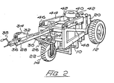
- the device there illustrated has a welded steel frame 10 provided with a pair of rearwardly disposed driving wheels 12 and a forwardly disposed steerable wheel 14.
- the driving wheels 12 are drivable by hydraulic motors 16 to which oil under pressure is delivered from a pump 18 driven by a diesel engine 20.
- the steerable front wheel 14 is rotatably mounted in a steering fork 22 which is carried at the lower end of a pivot pin 24 mounted in bearings in brackets 26 projecting from the front of the frame.
- a tiller 28 for steering the device is connected to the pivot pin 24 and is braced by means of inclined support struts 30 connected to the steering fork 22.
- Flow and return pipes 32, 34 extend along the tiller to valve means 36 carried at its front end.
- a lever 38 for opening and closing the valve means to the flow of oil under pressure in opposite directions through the flow and return pipes can be operated by a person steering the device to cause the hydraulic motors to be driven in either direction. When the lever is in a neutral position, to which it returns automatically when released by the person operating the vehicle, there is hydraulic lock in the system so that the device is immovable in either direction. The device does not therefore require brakes.
- the device is provided with means whereby it can be connected to a trailer type vehicle beneath that part of the trailer normally connected to the so-called fifth wheel connection of a tractor unit.
- These means are constituted by a bearing sleeve 40 trunnion mounted at 42 to one end of a carrier 44, the latter being pivotally connected at 46 to the frame 10.
- a hydraulic ram 48 is pivotally connected beneath the carrier at that end which supports the bearing sleeve 40, the ram reacting against a lower part of the frame 10.
- the arrangement is such that when the device has been manoeuvred, as previously described, so that the bearing sleeve 40 is almost exactly beneath the depending coupling pin of the trailer which it is desired to move, the output of the pump 18 can be diverted to the hydraulic ram 48 (by valve means not shown) so that the bearing sleeve is brought into engagement with the coupling pin and then lifts the front end of the trailer.
- the device is such that when it has been connected to a a trailer vehicle as just described, the coupled combination can be manoeuvred very easily indeed and with much greater safety than when using a conventional tractor unit. This is because a person operating the device has excellent visibility underneath and around the sides of the trailer. It will be understood that such a device is only required to operate at a walking speed. Consequently, it can have a relatively small engine and can operate very quietly.
- the device is very compact and of very much smaller overall size than a conventional tractor unit and can therefore be much more easily parked out of the way when not in use.
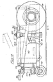
- the modified device there illustrated is very similar to that previously described in that it has a welded steel frame 10, a pair of rearwardly disposed driving wheels 12 and means whereby it can be connected to a trailer type vehicle, these means being constituted by the bearing sleeve 40 trunnion mounted at 42 to the carrier 44, the latter being pivotally connected at 46 to the frame.
- the device is provided with a pair of hydraulic rams 48, these being powered by a pump 18 driven by an engine 20.
- the engine is mounted towards the front of the device and the bearing sleeve 40 is located further forwardly than before for reasons of safety, that is to say to reduce the risk that the front end of the device might rear up when pulling a heavy trailer.
- a further variation from the previously described device is in the fact that the device is provided with a pair of steerable wheels 14, these being freely rotatable on the opposite ends of an axle 15 carried at the lower end of the pivot pin 24.
- the pivot pin is mounted in bearings in the brackets 26 projecting from the front of the frame, and the tiller 28 for steering the device is connected to the pivot pin.
- the safety means include a forwardly extending buffer element 50 which is slidably mounted relative to the tiller.
- the arrangement is such that on contacting an obstruction, which may of course be the body of the person steering the device, the buffer element is displaced against the force of a spring 52 and ' actuates a micro switch 54 to cut off the drive to the power driven wheels 12.
- the drive to the power driven wheels can of course be cut off in a number of ways.
- the actuation of the micro switch may be arranged to stop the engine or may be arranged to bring about hydraulic lock in the hydrostatic transmission.
- displaceable buffer element does not of course interfere with the movement of the lever 38 for opening and closing the valve means which cause the hydraulic motors to be driven in either direction as required.
- the hydraulic transmission of the device described and illustrated is capable of braking the device, it may be thought desirable to fit the device with braking means acting on the transmission mechanism and/or with conventional brakes acting on at least one of the wheels or on at least a pair of the wheels to be operated by a manually operable lever.
- the device can of course be fitted either with a diesel engine or with a petrol engine.
Landscapes
- Engineering & Computer Science (AREA)
- Chemical & Material Sciences (AREA)
- Combustion & Propulsion (AREA)
- Transportation (AREA)
- Mechanical Engineering (AREA)
- Guiding Agricultural Machines (AREA)
Claims (4)
Applications Claiming Priority (2)
| Application Number | Priority Date | Filing Date | Title |
|---|---|---|---|
| GB8127006 | 1981-09-07 | ||
| GB8127006 | 1981-09-07 |
Publications (3)
| Publication Number | Publication Date |
|---|---|
| EP0074236A2 EP0074236A2 (de) | 1983-03-16 |
| EP0074236A3 EP0074236A3 (en) | 1985-08-28 |
| EP0074236B1 true EP0074236B1 (de) | 1987-06-03 |
Family
ID=10524349
Family Applications (1)
| Application Number | Title | Priority Date | Filing Date |
|---|---|---|---|
| EP19820304564 Expired EP0074236B1 (de) | 1981-09-07 | 1982-08-31 | Steuerungsgerät zum Bewegen von Anhängerfahrzeugen |
Country Status (2)
| Country | Link |
|---|---|
| EP (1) | EP0074236B1 (de) |
| DE (1) | DE3276479D1 (de) |
Cited By (2)
| Publication number | Priority date | Publication date | Assignee | Title |
|---|---|---|---|---|
| DE4336170A1 (de) * | 1992-10-22 | 1994-06-01 | Peter Kessler | Bergungs- und Transporteinrichtung, vorzugsweise für Kraft- und Schienenfahrzeuge |
| CN104401412A (zh) * | 2014-11-15 | 2015-03-11 | 江苏海鹏特种车辆有限公司 | 手动转向液压牵引车 |
Families Citing this family (10)
| Publication number | Priority date | Publication date | Assignee | Title |
|---|---|---|---|---|
| GB2193935B (en) * | 1986-08-14 | 1990-04-25 | Brian James Afford | Device for moving trailers, caravans and the like |
| FR2641755A1 (fr) * | 1988-12-27 | 1990-07-20 | Mazenod Antoine | Appareil tracteur autorisant le travail d'arbustes disposes en haie plate et continue et/ou la recolte de fruits |
| AU681377B2 (en) * | 1993-04-21 | 1997-08-28 | Muvit International Pty. Ltd. | Improvements to vehicles |
| DE9411099U1 (de) * | 1994-07-08 | 1994-11-10 | Thielen Albert | Schleppendes Flurförderfahrzeug |
| GB0207776D0 (en) * | 2002-04-04 | 2002-05-15 | Mastermover Internat Ltd | Load transfer device |
| GB2404903B (en) * | 2003-08-13 | 2006-04-12 | Mastermover Internat Ltd | Load transport assembly |
| EP1686046B1 (de) * | 2005-01-27 | 2007-12-05 | Martin Nester | Sebstfahrendes Rangierfahrzeug für einen Sattelanhänger |
| ITPG20070062A1 (it) * | 2007-10-26 | 2009-04-27 | Gavarini Srl | Assale motorizzato per la movimentazione di rimorchi e simili macchine statiche |
| DE102016010575A1 (de) * | 2016-09-02 | 2018-03-08 | Man Truck & Bus Ag | Straßenfahrzeug-Zugkombination mit einer Zugmaschine und einem Trailer als Sattelauflieger |
| EP4137391A1 (de) * | 2021-08-18 | 2023-02-22 | ANT Maschinen GmbH | Roboterzugmaschine |
Family Cites Families (11)
| Publication number | Priority date | Publication date | Assignee | Title |
|---|---|---|---|---|
| GB606857A (en) * | 1946-01-21 | 1948-08-20 | Electruks Ltd | Improvements in or relating to electrical or petrol driven trucks and similar vehicles |
| US2878884A (en) * | 1952-07-24 | 1959-03-24 | Irvin F Schreck | Front wheel drive tow tractor |
| BE527897A (de) * | 1953-08-21 | |||
| US2867451A (en) * | 1954-09-14 | 1959-01-06 | Clark Equipment Co | Machine for handling semitrailers |
| FR1216706A (fr) * | 1959-02-13 | 1960-04-27 | Véhicule à usages multiples pour le transport d'engins de travaux publics et autres | |
| US3166141A (en) * | 1960-07-15 | 1965-01-19 | Morton K Shields | Tractor |
| US3105704A (en) * | 1962-05-17 | 1963-10-01 | Arthur G Schramm | Steerable dolly |
| US3179196A (en) * | 1963-08-28 | 1965-04-20 | Robert L Richardson | Trailer handling device |
| US3352374A (en) * | 1965-10-18 | 1967-11-14 | Ottawa Steel Products | Trailer tractor |
| US3679233A (en) * | 1971-03-10 | 1972-07-25 | Baker Calvin L | Vertically adjustable trailer hitch |
| US3924701A (en) * | 1974-10-11 | 1975-12-09 | Colin G Johnstone | Two-speed, self-propelled dolly for moving and elevating a mobile home or other load |
-
1982
- 1982-08-31 EP EP19820304564 patent/EP0074236B1/de not_active Expired
- 1982-08-31 DE DE8282304564T patent/DE3276479D1/de not_active Expired
Cited By (2)
| Publication number | Priority date | Publication date | Assignee | Title |
|---|---|---|---|---|
| DE4336170A1 (de) * | 1992-10-22 | 1994-06-01 | Peter Kessler | Bergungs- und Transporteinrichtung, vorzugsweise für Kraft- und Schienenfahrzeuge |
| CN104401412A (zh) * | 2014-11-15 | 2015-03-11 | 江苏海鹏特种车辆有限公司 | 手动转向液压牵引车 |
Also Published As
| Publication number | Publication date |
|---|---|
| EP0074236A2 (de) | 1983-03-16 |
| EP0074236A3 (en) | 1985-08-28 |
| DE3276479D1 (en) | 1987-07-09 |
Similar Documents
| Publication | Publication Date | Title |
|---|---|---|
| US4629020A (en) | Steerable device for moving trailer type vehicles | |
| EP0074236B1 (de) | Steuerungsgerät zum Bewegen von Anhängerfahrzeugen | |
| CA2521813C (en) | Trailer mule vehicle for moving semi-trailers | |
| US5988304A (en) | Wheelchair combination | |
| US4944522A (en) | Pin retractor for semi-trailer tandems | |
| US4911603A (en) | Aircraft towing vehicle having swiveled nose wheel lifter | |
| US3439764A (en) | Power caster for moving trailers | |
| EP1765659B1 (de) | Traktoreinheit und -kupplungsvorrichtung | |
| US4856814A (en) | Adjustable, proportionally steerable auxiliary wheel asemblies for trucks | |
| US5346354A (en) | Carriage for transferring objects | |
| US4823895A (en) | Three wheeled vehicle with combined power transmission and steering system | |
| CA1223913A (en) | Tracked load carrying vehicle | |
| EP0460049B1 (de) | Hilfsanordnung in fahrzeugen | |
| WO2004028903A1 (en) | Tractor, particularly for towing aircraft | |
| EP0442874B1 (de) | Wagen zum transport von gegenständen | |
| CA1214395A (en) | Steerable device for moving trailer type vehicles | |
| US3848692A (en) | Dual brake on drive and idler wheels of industrial trucks | |
| JPH01297345A (ja) | 前輪駆動自動車用持上及び操縦装置 | |
| US5738376A (en) | Automobile parking aid mechanism | |
| CA1058657A (en) | Steerable trailer | |
| US4453620A (en) | Automatic safety brake actuation tongue for towed vehicles | |
| JPH10109649A (ja) | 牽引車 | |
| EP0582204B1 (de) | Schleppfahrzeug für Flugzeuge | |
| US6029779A (en) | Automatic parking brake and steering spindle | |
| JP3142552B2 (ja) | 自動車用多目的補助無限軌道装置 |
Legal Events
| Date | Code | Title | Description |
|---|---|---|---|
| PUAI | Public reference made under article 153(3) epc to a published international application that has entered the european phase |
Free format text: ORIGINAL CODE: 0009012 |
|
| AK | Designated contracting states |
Designated state(s): BE DE FR GB NL |
|
| PUAL | Search report despatched |
Free format text: ORIGINAL CODE: 0009013 |
|
| AK | Designated contracting states |
Designated state(s): BE DE FR GB NL |
|
| 17P | Request for examination filed |
Effective date: 19851111 |
|
| 17Q | First examination report despatched |
Effective date: 19860526 |
|
| GRAA | (expected) grant |
Free format text: ORIGINAL CODE: 0009210 |
|
| AK | Designated contracting states |
Kind code of ref document: B1 Designated state(s): BE DE FR GB NL |
|
| REF | Corresponds to: |
Ref document number: 3276479 Country of ref document: DE Date of ref document: 19870709 |
|
| ET | Fr: translation filed | ||
| PLBE | No opposition filed within time limit |
Free format text: ORIGINAL CODE: 0009261 |
|
| STAA | Information on the status of an ep patent application or granted ep patent |
Free format text: STATUS: NO OPPOSITION FILED WITHIN TIME LIMIT |
|
| 26N | No opposition filed | ||
| PGFP | Annual fee paid to national office [announced via postgrant information from national office to epo] |
Ref country code: FR Payment date: 19890818 Year of fee payment: 8 |
|
| PGFP | Annual fee paid to national office [announced via postgrant information from national office to epo] |
Ref country code: DE Payment date: 19890824 Year of fee payment: 8 |
|
| PGFP | Annual fee paid to national office [announced via postgrant information from national office to epo] |
Ref country code: BE Payment date: 19890830 Year of fee payment: 8 |
|
| PGFP | Annual fee paid to national office [announced via postgrant information from national office to epo] |
Ref country code: NL Payment date: 19890831 Year of fee payment: 8 Ref country code: GB Payment date: 19890831 Year of fee payment: 8 |
|
| PG25 | Lapsed in a contracting state [announced via postgrant information from national office to epo] |
Ref country code: GB Effective date: 19900831 Ref country code: BE Effective date: 19900831 |
|
| BERE | Be: lapsed |
Owner name: CRAVEN TASKER (SHEFFIELD) LTD Effective date: 19900831 |
|
| PG25 | Lapsed in a contracting state [announced via postgrant information from national office to epo] |
Ref country code: NL Effective date: 19910301 |
|
| NLV4 | Nl: lapsed or anulled due to non-payment of the annual fee | ||
| PG25 | Lapsed in a contracting state [announced via postgrant information from national office to epo] |
Ref country code: FR Effective date: 19910430 |
|
| GBPC | Gb: european patent ceased through non-payment of renewal fee | ||
| PG25 | Lapsed in a contracting state [announced via postgrant information from national office to epo] |
Ref country code: DE Effective date: 19910501 |
|
| REG | Reference to a national code |
Ref country code: FR Ref legal event code: ST |