EP0074155A1 - A device for spreading granular and/or powdery material - Google Patents
A device for spreading granular and/or powdery material Download PDFInfo
- Publication number
- EP0074155A1 EP0074155A1 EP82201092A EP82201092A EP0074155A1 EP 0074155 A1 EP0074155 A1 EP 0074155A1 EP 82201092 A EP82201092 A EP 82201092A EP 82201092 A EP82201092 A EP 82201092A EP 0074155 A1 EP0074155 A1 EP 0074155A1
- Authority
- EP
- European Patent Office
- Prior art keywords
- distribution
- distribution member
- distribution members
- hopper
- members
- Prior art date
- Legal status (The legal status is an assumption and is not a legal conclusion. Google has not performed a legal analysis and makes no representation as to the accuracy of the status listed.)
- Ceased
Links
- 239000000463 material Substances 0.000 title claims abstract description 84
- 230000007480 spreading Effects 0.000 title claims abstract description 17
- 238000003892 spreading Methods 0.000 title claims abstract description 17
- 238000009826 distribution Methods 0.000 claims abstract description 148
- 230000007246 mechanism Effects 0.000 claims description 17
- 210000003414 extremity Anatomy 0.000 claims description 14
- 230000008878 coupling Effects 0.000 claims description 8
- 238000010168 coupling process Methods 0.000 claims description 8
- 238000005859 coupling reaction Methods 0.000 claims description 8
- 239000003337 fertilizer Substances 0.000 claims description 4
- 210000003141 lower extremity Anatomy 0.000 claims description 3
- 210000001364 upper extremity Anatomy 0.000 claims description 2
- 238000000034 method Methods 0.000 claims 2
- 238000010276 construction Methods 0.000 description 6
- 238000004519 manufacturing process Methods 0.000 description 2
- 239000002184 metal Substances 0.000 description 2
- 238000009827 uniform distribution Methods 0.000 description 2
- 230000008901 benefit Effects 0.000 description 1
- 230000008859 change Effects 0.000 description 1
- 238000003825 pressing Methods 0.000 description 1
- 239000000126 substance Substances 0.000 description 1
Images
Classifications
-
- A—HUMAN NECESSITIES
- A01—AGRICULTURE; FORESTRY; ANIMAL HUSBANDRY; HUNTING; TRAPPING; FISHING
- A01C—PLANTING; SOWING; FERTILISING
- A01C17/00—Fertilisers or seeders with centrifugal wheels
- A01C17/005—Driving mechanisms for the throwing devices
-
- A—HUMAN NECESSITIES
- A01—AGRICULTURE; FORESTRY; ANIMAL HUSBANDRY; HUNTING; TRAPPING; FISHING
- A01C—PLANTING; SOWING; FERTILISING
- A01C17/00—Fertilisers or seeders with centrifugal wheels
- A01C17/006—Regulating or dosing devices
- A01C17/008—Devices controlling the quantity or the distribution pattern
Definitions
- This invention relates to a device for spreading granular and/or powdery material, such as fertilizer, seeds or suchlike material, comprising a frame, a hopper and at least two distribution members adapted to move about rotary axes.
- the two distribution members are arranged at a short distance from one another and coupled with a driving mechanism designed so that the distribution members can be driven at will with any one of two or more different speeds.
- a device is obtained by which the width over which the material is spread in one run can be controlled in a simple manner, whilst a uniform distribution pattern is obtained.
- An advantageous disposition of the distribution members is obtained when the parts of the distribution members nearest one another are spaced apart by a distance of about 2 cms.
- a further .aspect of the invention is concerned with a device of the kind set forth in the preamble in which the distribution members are coupled with a driving mechanism which is formed so that the distribution members can be rotated with a speed of at least 1040 rev/min.
- the driving mechanism of the distribution members it is advantageous for the driving mechanism of the distribution members to comprise a plurality of gear wheels arranged in a gear box and being in mesh with one another between the distribution members, which are thereby coupled with one another. In this way it can be ensured that the two distribution members are driven with the same speed of rotation.
- a further aspect of the invention relates to a device of the kind set forth in which in accordance with the invention the gear wheels arranged between the two distribution members are spur gear wheels rotatable about upwardly extending rotary axes and arranged in a gear box forming a flat, hollow beam between frame parts. This can have an advantageous effect on a low construction of the device.
- the hopper is made from a single piece of material.
- the hopper can be readily made, whilst its lifetime will be satisfactory.
- the quantity of material to be carried for a run can be effectively raised by mounting an extension piece on the hopper.
- the hopper has two delivery spouts, each of which adjoins a distribution member, whereby at least one delivery spout is provided with delivery means adapted to move with respect to the hopper in a manner such that the place where the material is fed to the distribution member is displaceable about the rotary axis of the distribution member and/or in a radial direction relative to the rotary axis of the distribution member, the circumferential angle through which the material leaves the circumference of the distribution member being adjustable.
- a spreading device is obtained by which the material can be spread in many ways so that during its travel the device can spread the material at will for example, either on a narrow strip or on a very wide strip.
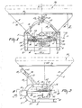
- the spreading device illustrated in the Figures comprises a frame 1, on which a hopper 2 is arranged and which is provided with two distribution members 3 and 4, which are located beneath the hopper.
- the frame 1 has a symmetrical shape with respect to the vertical plane 7 going through the longitudinal centre line of the device and extending in the intended direction 69 of operative travel of the device.
- the frame comprises two side beams 5 and 6 bent in the form of a U and extending parallel to the plane 7.
- Each of the side beams 5 and 6 has a straight upper limb 8 and a straight lower limb 9, these limbs being horizontal in the horizontal position of the device.
- the limbs 9 of the frame beams 5 and 6 are interconnected by a square-section, hollow transverse beam 10 and a channel-shaped rear beam 11 fastened to the ends of the limbs 9.
- the limbs of the rear beam 11 have holes 12, the centres of which are located in the longitudinal plane 7.
- the limbs 8 are interconnected by a v-shaped tie beam 12 fastened to the upper surfaces of the limbs 8 and being furthermore fastened to the beams 5 and 6 by struts 14.
- the tie beam 13 slopes upwardly and forwardly away from the limbs 8 at an angle of about 45°.
- the beams 5 and 6 are each provided with two coupling strips 15, and the curved top part of the beam 13 is provided with coupling strips 16.
- Each of the side beams 5 and 6 is provided with an angle-section carrying beam 20, which is parallel to the limbs 8 and 9.
- the carrying beams 20 extends away from the curved parts of the side beams 5 and 6 in the same direction as the limbs 8 and 9 and from the curved parts they extend to the rear with respect to the direction 69.
- the connection of the carrying beams 20 with the side beams is reinforced by vertical stiffening plates 21 located between the respective limbs 8 and the beam 20.
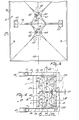
- the carrying beams 20 are intercoupled by a horizontal gear box 22.
- the gear box 22 comprises a lower panel 23 to the ends of which are welded fastening plates 24 which are connected with the carying beams 20 by means of bolts 25.
- the gear box 22 comprises an upper panel 26, which is coupled with the lower panel by means of bolts 27.
- the bolts 27 extend across protruding rims 28 and 29 of the lower and upper panels and the lower and upper panels are symmetrical with respect to the horizontal plane where the lower and upper panels join one antoher as is shown in the Figures.
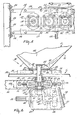
- each of the distribution members 3 and 4 comprises a plate 33 fastened at right angles to the shaft concerned and provided with ejection blades 34.
- the plates 33 of the two distribution members are located with their ejection blades at the same level and are rotatable in the same plane.
- the ejection blades 34 of the two distribution members are offset from one another with the result that they pass alternately the point of closest approach of the two distribution members.
- the shafts 31 and 32 are journalled in a bearing housing 35 arranged in the lower panel 23 and a bearing housing 36 arranged in the upper panel 26.
- the shafts 31 and 32 are provided with spur gear wheels 37 and 38, located in the gear box. Between the gear wheels 37 and 38 are arranged two gear wheels 39 and 40.
- the gear wheels 37 to 40 are in horizontal positions and in mesh with one another as will be apparent from Figures 4 and 5.
- the gear wheels 39 and 40 are arranged on vertical shafts 41 and 42, which are journalled in the gear box in bearing housings corresponding with the bearing housings 35 and 36 of Figure 6.
- the shaft 42 extends downwards across the bearing housing in the lower panel and its lower end is located in a gear box 43 forming a driving box.
- the gear box 43 is arranged in a manner not shown in detail at the lower side of the gear box 22 and is provided with a driving shaft 44, which extends in a horizontal direction in the horizontal position of the device and whose end 45 emerging from the front side ot the gear box 43 constitutes a coupling part.
- the shaft 44 is provided with a spur gear wheel 46, which co-operates with a spur gear wheel 47.
- the gear wheel 47 is arranged on a shaft 48 which is journalled in the gear box 43 and is parallel to the shaft 44.
- the shaft 48 is provided with a bevel gear wheel 49 which is in mesh with a bevel gear wheel 50 on the shaft 42.
- the gear wheels 46 and 47 are releasably arranged on the shafts 44 and 48 respectively and constitute with one another and, as the case may be, with other sets of gear wheels, exchangeable and interchangeable sets of wheels.
- the gear box 43 is provided with a readily removable cover 51 for exchanging and interchanging the gear wheels 46 and 47.
- the cover 51 is provided to this end with knobs 52.
- the frame 1 is provided with a fastening plate 55 and the ends of the limbs 8 of the side beams 5, 6 are provided with supports 56.
- the hopper 2 is mounted on the frame 1 on the fastening plate 55 and the supports 56 by means of bolts 57 and 58 respectively.
- the hopper 2 constitutes a single unit, which may be obtained by pressing a metal plate, whilst the two delivery spouts 59 and 60 are formed on the hopper 2.
- the hopper 2 has four flat sides and has a rectangular shape, viewed on plan. The delivery spouts 59 and 60 change from top to bottom into round bottom openings 61 and 62.
- the delivery spouts 59 and 60 are located above the distribution members 3 and 4 and the centre lines 63 and 64 of the shafts 31 and 32 coincide with the centre lines of the openings 61 and 62.
- the centre lines 63 and 64 which constitute rotary axes of the distribution members 3 and 4, are spaced apart by a distance 65, which is only slightly greater than the diameter 66 of the distribution members 3 and 4 as will be apparent from Figures 1 and 4.
- the proximal sides of the distribution members 3 and 4 are spaced apart by a very short distance 67, for example, 2 cms.
- the two distribution members 3 and 4 are arranged side by side so that the centre lines 63 and 64 are located in a vertical plane 68 extending transversely of the direction 69, when the machine is in a horizontal position.
- the hopper 2 is symmetrical to the plane 7 as well as to the plane 68.
- the front and rear walls 70 and 71 respectively of the hopper are at an angle of 45° to the horizontal.
- the front wall 70 extends along the beam 13 ( Figure 2). Near the top, the walls 70 and 71 are interconnected by a stiffening bar 76, which is horizontal in a horizontal position of the device and extends in the direction 69.
- the centre line of the stiffening bar 76 is located in the plane 7.
- the integral hopper has a height 72, which is four to five times the height 73 of the individual delivery spouts 59 and 60.
- the middle of each support 56 is located in the plane 68 and the limb 8 of each side beam 5 and 6 terminates in front of the plane 68, whereas the limb 9 of each of these beams is located at a distance behind the plane 68 such that, as viewed on plan, the beam 11 is further away from the plane 68 than is the circumference of each distribution member 3 and 4, as will be particularly apparent from Figures 2 and 4.
- the hopper 2 has a bent-over rim 74, on which an extending piece 75 can be arranged to enlarge the hopper capacity.
- the extending piece 75 is indicated in Figures 1 and 2 by broken lines.
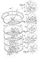
- the bottom openings 61 and 62 of the delivery spouts 59 and 60 are provided with bottom plates 80 nd 81, which are rigidly secured to the undersides of the delivery spouts 59 and 60 respectively.
- dosing mechanisms 86 each of which comprises four dosing plates 82, 83, 84, and 85, as is shown in detail for the dosing mechanism 86 between the bottom 81 and the distribution member 4.
- the bottom plate 81 and each of the dosing plates 82 to 85 have a central opening 87, through which extends the shaft 32 of the distribution member 4 down to the underside of the delivery spout 60.
- the centres of the openings 87 coincide with the rotary axis 64.
- the shaft 32 is provided with a member 88 affecting the material.
- the dosing plates 82 to 85 are adapted to turn about the shaft 32 with respect to one another and to the bottom 81.
- each of the dosing plates 82 to 85 is connected with a setting mechanism by which they can be displaced and be maintained in a desired position relative to one another and to the bottom 81.
- the connection of the dosing plates with the setting mechanism and the setting mechanism are not shown in detail.
- the dosing plates 82 to 85 are arranged in the device in a manner not shown in detail so that they can be readily turned with respect to one another, whilst the dosing plate 82 can be readily turned with respect to the bottom 81.
- the bottom plate 81 has a delivery orifice 91 extending to both sides of a vertical plane 92 extending in the direction 69 and containing the rotary axis 64.
- the delivery orifice 91 subtends an angle 93 of about 98° at the rotary axis 64.
- the orifice 91 covers an angle 95 of about 60° on the side of the vertical plane 92 remote from the spout 59 with the distribution member 3.
- the orifice 91 covers a further angle 94 of about 38°.In a radial direction the orifice 91 covers a distance 96, which is substantially equal to the whole radial distance of the bottom plate 81, whilst only near the hole 87 there is a small rim 70 and near the outer circumference a small rim 98.
- the dosing plate 62 has passages 100 and 101 exteding in a radial direction with respect to the rotary axis 64 over a distance equal to the distance 96 and, viewed in a radial direction, they are lcoated below the delivery orifice 91.
- the passages 100 and 101 are separated from one another by a small strip 102 and each of them covers equal distances 103 and ' 104, measured in a radial direction.
- the passage 100 covers an angle 105 of about 35° around the axis 64, whereas the passage 101 covers an angle 106 of about 115° around the rotary axis 64.
- the passage 100 is nearer the rotary axis 64 than the passage 101 and is located inside the angle 106 of the passage 101.
- the passage 100 is spaced apart by an angle 107 of about 30° from the end 108 of the passage 101. Said end 108 being remote from the side of the dosing plate directed to the interior of the device, or respectively, the other delivery spout 59.
- the dosing plate 83 has passages 109 and 110, the size and location of which relative to one another and to the rotary axis correspond with those of the passages 100 and 101 of the dosing plate 82.
- the dosing plates 82 and 83 are identical.
- the dosing plate 84 has two passages 115 and 116 spaced apart in a radial direction to the rotary axis 64 by a distance such that the passage 115 is nearer the rotary axis 64 than the passage 116.
- the passages 115 and 116 extend in a radial direction, like the passages in the bottom 81 and the dosing plates 82 and 83, over a distance 96.
- the passages 115 and 116 cover equal distances 103 and 104 so that their distances from the rotary axis 64 correspond with the distances between the passages 100, 101 and 109, 110 and the axis 64.
- the passage 115 covers an angle 117 of about 90° around the rotary axis 64, whereas the passage 116 covers an angle 118 of about 25° around the axis 64.
- the passage 116 is located completely inside the angle 117 and the passage 116 is off-set through an angle 119 of about 30° with respect to the radial side 120 of the angle 115 remote from the medium side of the device or, respectively, the other delivery spout 59.
- the dosing plate 85 is identical to the dosing plate 84 and has two passages 121 and 122, the size of which is equal to that of the passages 115 and 116, whilst their positions relative to one another and to the rotary axis 64 are the same as those of the passages 115 and 116.
- the bottom plate 80 has a delivery orifice 91.
- thedelivery orifice in the bottom plate 80 is located so that with the orifice 91 it is symmetrical to the vertical, longitudinal plane 7.
- the passages in the dosing plates beneath the bottom plate 80, as stated for the delivery orifices in the bottom plates 80 and 81, are symmetrical to the vertical plane 7.
- the device When the device is put into use, it is hitched via the coupling strips 15 and 16 to the three-point lifting device of a tractor.
- the coupling end 45 of the driving shaft 44 is coupled with the power take-off shaft of the tractor or a similar vehicle.
- the device serves to spread distributable material, particularly fertilizer, seeds or similar substances on a field.
- the material can be carried in the hopper 2.
- the amount of material carried for a single run may be raised by mounting the extension rim 75 on the upper rim 74 of the hopper 2 so that, for example, twice the initial amount of material can be carried by the device.
- the material can be fed from the hopper 2 to the distribution members 3 and 4 through the delivery orifices 91 in the bottoms 80 and 81 and through the passages of the various dosing plates 82 to 85.
- the distribution member: 3 and 4 are rotated in the direction of the arrows 125 and 126 from the power take-off shaft of the tractor via the driving shaft 44 and the gear wheels in the gear box 43 and the gear box 22.
- the distribution members rotate in opposite senses and the proximal sides of the distribution members move in the direction 69.
- the direction in which the material is ejected by each of the distribution members having a given diameter 60 depends on the speed of rotation of the distribution member and the place where the material is fed from the hopper to the distribution member with respect to the rotary axis of the distribution member and the direction of movement 69.
- the speed of rotation of the distribution members 3 and 4 may be fixed at will at any one of several values by interchanging the gear wheels 46 and 47 or by exchanging these gear wheels for a different set of gear wheels.
- the place on each of the distribution members which receives the material can be changed by turning one or more of the dosing plates 82 to 85 with respect to one anotehr and/or with respect to the bottom 80 or 81 respectively.
- the passages 100 and 109 cooperating with one another constitute a port located below the orifice 91 of the bottom 81 and relatively near the rotary axis 64.
- the passages 116 and 122 of the dosing plates 84 and 85 form a port relatively remote from the rotary axis 64 below the orifice 91 and below the elongate passages 101 and 110.
- the passages 100 and 109 co-operate below the orifice 91 and above the passages 115 and 121 to form a port or delivery opening of a given size to deliver material out of the hopper.
- the place of the passages 100 and 109 within the circumferential angle 93 of the orifice 91 and the circumferential angle 117 of the passages 115 and 121 is adjustable about the iotary axis 64.
- the registering passages 116 and 122 constitute a port or outlet opening of a given size below the orifice 91 and below the passages 101 and 110, said size being variable within the circumferential angle 93 of the orifice 91 and the circumferential angles 106 of the passages 101 and 110 about the rotary axis 64.
- the sectors in which are located the various orifices in the bottom and the various dosing plates are chosen so that the port formed by the passages 100 and 109 and the port formed by the passages 116 and 122.can be shifted, within given limits, relatively to one another and/or in common about the rotary axis 64 and be fixed. Therefore, the place receiving the material on the distribution member concerned can be widely varied.
- the material should be fed over a comparatively large distance 96 to the distribution member and that the place where the material can be fed through the passages 100 and 109 near the axis 64 to the distribution member should be displaceable with respect to the place where the material is fed thorugh the passages 116 and 122 far from the rotary axis 64 to the distribution member.
- the circumferential angle in which the material leaves the circumference of the distribution member can be varied within wide limits. It is important that the material flowing through the port formed by the passages 100 and 109 should reach the distribution member further away from the circumference thereof an hence should cover a longer path on the distribution member than the material fed to the distribution member through the port formed by the passages 116 and 122.
- the ports formed by the passages 100 and 109 and the passages 116 and 122 can be disposed relatively to one another so that the flows from these ports reach the distribution member more or less separately and move along adjacent or contiguous paths of the distribution member towards the circumference there of so that the material can lcave the circumference of the distribution member over a large circumferential angle.
- the dosing plates 82 to 85 can also be adjusted so that the material fed through the passages 100 and 109 to the distribution member moves towards the circumference thereof along a path which coincides with the path along which the material fed through the passages 116 and 122 will move to the circumference of said distribution member. When the two paths overlap one another, the material will leave the circumference of the distribution member over a relatively small circumferential angle.
- a satisfactory feed of material to the distribution members is obtained when, viewed in a direction parallel to the rotary axes, the passages are located inside an imaginary circle 137 on which are located the inner ends 138 of the ejection blades 34.
- the speed of rotation of the distribution members and the place where the material is fed to the distribution members can be set so that the material can be sprcad at will in one of a large number of directions in sectors of selected width by each of the distribution members.
- the location of the orifices 91 and the bottoms 80 and 81, the sense of rotation and the variable speed of rotation of the distribution members as well as the diameters thereof are chosen so that the distribution members can spread the material in coinciding sectors or in sectors coinciding partly or not coinciding at all.
- the device is particularly suitable for spreading material in a manner such that the distribution members covel coinciding sectors.
- the distribution members rotate in the opposite senses 125 and 126 whilst the delivery orifices 91 and the passages in the various dosing plates are located symmetrically on both sides of the plane 7 so that the distribution members spread the material in symmetry with respect to the vertical plane 7.
- the speed of rotation of the distribution members will be relatively high and the place of reception of the material on the distribution members will be set so that the material leaves the circumference of the distribution members in a large circumferential angle so that it is spread in a wide sector.
- Figure 13 shows a position of the dosing plates 82 to 85 in which the material leaves the circumference of the distribution member in a circumferential angle 128 ( Figures 4 and 13) of about 150°.
- the passages 100 and 109 are set so that they form a port 129 which, with respect to the direction of rotation 126, leads with respect to a port 130 formed by the passages 116 and 122.
- the ports 129 and 130 constitute the outlets of the delivery means of the hopper formed by the bottom 80 and the dosing plates 82 to 85. Since the bottom 80 with the dosing plates 82 to 85 are in a horizontal position like the distribution member 4, the location of the ports 129 and 130 will correspond to the place where the material reaches the distribution member.
- the locations of the circumferential angles 127 and 128 can be varied about the rotary axis 63 and 64 respectively by turning in common the dosing plates 82 to 85 about the respective rotary axes, whilst their relative positions are main- .tained.
- the ports 129 and 130 have to be kept within the angle 93 of the delivery orifice 91. This setting is important for the distribution of different kinds of material.
- Figure 14 shows a position of the dosing plates 82 to 85 in which a port 131 is formed by the passages 100 and 109 and a port 132 formed by the passages 116 and 122.
- the ports 131 and 132 are in such relative positions that with respect to the direction of rotation 126 the port 132 leads with respect to the port 131.
- This disposition of the ports 131 and 132 results in that material passing through the port 131 reaches the distribution member and flows along a path towards the circumference of the distribution member which coincides with the path along which the material emanating from the port 132 moves towards the circumference of the distribution member.
- the sizes of the ports 131 and 132 are smaller than those of the ports 129 and 130 since the dosing plates 82 and 83 and the dosing plates 84 and 85 are relatively arranged so that the passages 100 and 109 and the passages 116 and 122 coincide only partly, owing to the selected setting of the dosing plates 84 and 85 relative to one another.
- the material will leave the circumference of the distribution member over an angle of about 45° so that the distribution member 4 will spread the material over a relatively narrow sector 136.
- the distribution member 3 will spread the material on a sector lying symmetrically with respect to the vertical plane 7 with the sector covered by the distribution member 4.
- the distribution members 3 and 4 will spread the material on nonoverlapping sectors so that during the run of the device the material is deposited on adjacent strips of land.
- the two distribution members can spread the material symmetrically about the plane 7, whilst the dosing plates 82 to 85 below the bottoms 80 and 81 are symmetrical to said plane 7. It is, however, also possible to cause one distribution member to spread the material in a way differing from the other distribution member. For example, one distribution member may spread the material in a direction differing from the spreading direction of the other distribution member. Moreover, the dosing plates of the two dosing mechanisms may be differently set in a manner such that the distribution members spread the material in sectors of different widths.
- each dosing plate has two passages spaced apart by different distances from the rotary axis, a satisfactory distribution of the material on the distribution member is obtained, whilst the possibilities of adjustment are enhanced.
- the strip 102 between the passages 100 and 101 may be omitted.
- the hopper 2 has, in general, sufficient capacity to carry material for one or more runs.
- the construction is particularly advantageous with a hopper 2 having a capacity of 400 litres and an extension piece 75 also having a capacity of 400 litres. Thus, when the extension piece is used, 800 litres of material can be carried.
- the size and shape of the hopper 2 shown are such that it can be readily pressed from a single piece of metal or be made in a different way from a single piece of material.
- Making the hopper integrally from a piece of material can be simplified by using a small height 73 of the delivery spouts 59 and 60 as compared with the overall height 72.
- the capacity of the hopper is maintained as large as possible. It may be advantageous to arrange the distribution members as closely as possible to one another and to use distribution members of moderate diameter so that the delivery spouts need not be spaced apart by a great distance.
- This structure of the hopper ensures, in addition, a satisfactory flow of material from the hopper thorugh the delivery spouts.
- the diameter 66 of the distribution members is about 35 cms and the distance 65 between the rotary axes 63 and 64 of the distribution members is about 37 cms.
- the delivery spouts 59 and 60 can thus be near one another, whilst the overall width of the hopper need not be excessively great.
- the width of the frame may be small. Therefore the quantity of material required for constructing the device is minimized, which is conducive to the manufacture of the frame and the hopper.
- the structure of the frame and the hopper shown ensures an advantageous and cheap manufacture.
- the height of the gear box 22 with the horizontal gear wheels 37 to 40 may be small, which is advantageous to obtain a low construction.
- the box 22 constitutes a satisfactory stiffening part between the beams 20 and a satisfactory support for the distribution members. Mounting and fixation of the gear box 22 can be readily carried out, since the lower panel 23 is rigidly connected with the beams 20 by means of the bolts 25, whilst the cover or upper panel 26 can be arranged on the beams 20 independently of the fixation of the lower tray 23.
- the diameter of the distribution members may very advantageously be kept small, whilst nevertheless the material can be spread over a large width, when the distribution members can be rotated at a comparatively high speed.
- the speed of rotation exceeds about 1040 rev/min so that the spreading width may amount to, for example, 24 metres.
- An advantageous speed of rotation of the distribution members may, for example, be 1500 rev/min.
- the adjustment of the speed of rotation of the distribution,members can be simply carried out by removing the cover 51 and replacing the gear wheels 46 and 47 by a different set of gear wheels or by interchanging them.
- the cover 51 can, to this end, be readily disengaged from the gear box 43.
- the adjustment of the speed of rotation ensures a satisfactorily controllable spreading width and a uniform distribution.
- the beams 11 and 10 of the frame 1, together with the beam 13 and the gcar box 22 constitute a satisfactory connection between the two curved side beams 5 and 6.
- the hole 12 in the beam 11 can be used to attach a further implement to the device, for example, a trailer carrying material to be spread.
Landscapes
- Life Sciences & Earth Sciences (AREA)
- Soil Sciences (AREA)
- Environmental Sciences (AREA)
- Fertilizing (AREA)
- Agricultural Chemicals And Associated Chemicals (AREA)
- Detergent Compositions (AREA)
Abstract
Distribution members (3, 4) of a spreading device are disposed close to each other. The distance (67) between the points of closest approach of the distribution members (3,4) may be 2 centimetres. The outside diameter of each distribution member may be 35 centimetres. Flow of material to a distribution member (4) of a spreading device is controlled by delivery means (86). The delivery means (86) comprises dosing plates (82, 83, 84, 85) which are independently displaceable relatively to each other and to the bottom (81) of a hopper of the device. The dosing plates (82, 83, 84, 85) and the bottom (81) have openings which cooperate with one another in an adjustable manner which makes it possible to adjust the position of the delivery of material to the distribution member (4) both in radial and circumferential directions, and to adjust the size of the or each delivery orifice.
Description
- This invention relates to a device for spreading granular and/or powdery material, such as fertilizer, seeds or suchlike material, comprising a frame, a hopper and at least two distribution members adapted to move about rotary axes.
- According to the invention the two distribution members are arranged at a short distance from one another and coupled with a driving mechanism designed so that the distribution members can be driven at will with any one of two or more different speeds. In this way a device is obtained by which the width over which the material is spread in one run can be controlled in a simple manner, whilst a uniform distribution pattern is obtained. An advantageous disposition of the distribution members is obtained when the parts of the distribution members nearest one another are spaced apart by a distance of about 2 cms.
- An advantageous construction of the device embodying the invention is obtained when during the operation of the device the parts furthest remote from the rotary axes of the distribution members are moving on a circle having a diameter of about 35 cms.
- A further .aspect of the invention is concerned with a device of the kind set forth in the preamble in which the distribution members are coupled with a driving mechanism which is formed so that the distribution members can be rotated with a speed of at least 1040 rev/min. As a result the material can be very uniformly spread over a large width. According to a further aspect it is advantageous for the driving mechanism of the distribution members to comprise a plurality of gear wheels arranged in a gear box and being in mesh with one another between the distribution members, which are thereby coupled with one another. In this way it can be ensured that the two distribution members are driven with the same speed of rotation.
- A further aspect of the invention relates to a device of the kind set forth in which in accordance with the invention the gear wheels arranged between the two distribution members are spur gear wheels rotatable about upwardly extending rotary axes and arranged in a gear box forming a flat, hollow beam between frame parts. This can have an advantageous effect on a low construction of the device.
- According to a further aspect of the invention in a device of the kind set forth the hopper is made from a single piece of material. In this way the hopper can be readily made, whilst its lifetime will be satisfactory. The quantity of material to be carried for a run can be effectively raised by mounting an extension piece on the hopper.
- According to a further aspect of the invention the hopper has two delivery spouts, each of which adjoins a distribution member, whereby at least one delivery spout is provided with delivery means adapted to move with respect to the hopper in a manner such that the place where the material is fed to the distribution member is displaceable about the rotary axis of the distribution member and/or in a radial direction relative to the rotary axis of the distribution member, the circumferential angle through which the material leaves the circumference of the distribution member being adjustable. In this way a spreading device is obtained by which the material can be spread in many ways so that during its travel the device can spread the material at will for example, either on a narrow strip or on a very wide strip.
- For a better understanding of the present invention and to show how it may be carried into effect, reference will now be made, by way of example, to the accompanying drawings, in which:
- Figure 1 is a front view of a spreading device embodying the invention;
- Figure 2 is a side elevation of the device taken in the direction of the arrow II in Figure 1;
- Figure 3 is a plan view of the device shown in Figures 1 and 2;
- Figure 4 is a plan view of the device of Figures 1 to 3, the hopper being omitted;
- Figure 5 is an enlarged view of part of Figure 4, the distribution members being omitted;
- Figure 6 is an enlarged sectional view taken on the line VI-VI in Figure 4;
- Figure 7 is an exploded view, in the direction of the arrow VII in Figure 6, of a dosing mechanism;
- Figure 8 is a plan view of the hopper bottom;
- Figure 9 is a plan view of a first dosing disc;
- Figure 10 is a plan view of a second dosing disc;
- Figure 11 is a plan view of a third dosing disc;
- Figure 12 is a plan view of a fourth dosing disc;
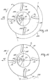
- Figure 13 is a plan view of the dosing nechanism and a distribution member;
- Figure 14 is a plan view corresponding to Figure 13 but shows the parts in a different operative condition.
- The spreading device illustrated in the Figures comprises a
frame 1, on which ahopper 2 is arranged and which is provided with twodistribution members 3 and 4, which are located beneath the hopper. Theframe 1 has a symmetrical shape with respect to thevertical plane 7 going through the longitudinal centre line of the device and extending in the intendeddirection 69 of operative travel of the device. The frame comprises twoside beams 5 and 6 bent in the form of a U and extending parallel to theplane 7. Each of theside beams 5 and 6 has a straight upper limb 8 and a straight lower limb 9, these limbs being horizontal in the horizontal position of the device. The limbs 9 of theframe beams 5 and 6 are interconnected by a square-section, hollow transverse beam 10 and a channel-shapedrear beam 11 fastened to the ends of the limbs 9. The limbs of therear beam 11 haveholes 12, the centres of which are located in thelongitudinal plane 7. The limbs 8 are interconnected by a v-shaped tie beam 12 fastened to the upper surfaces of the limbs 8 and being furthermore fastened to thebeams 5 and 6 bystruts 14. Thetie beam 13 slopes upwardly and forwardly away from the limbs 8 at an angle of about 45°. At their curved leading portions thebeams 5 and 6 are each provided with twocoupling strips 15, and the curved top part of thebeam 13 is provided withcoupling strips 16. Each of theside beams 5 and 6 is provided with an angle-section carryingbeam 20, which is parallel to the limbs 8 and 9. Thecarrying beams 20 extends away from the curved parts of theside beams 5 and 6 in the same direction as the limbs 8 and 9 and from the curved parts they extend to the rear with respect to thedirection 69. The connection of thecarrying beams 20 with the side beams is reinforced by verticalstiffening plates 21 located between the respective limbs 8 and thebeam 20. Thecarrying beams 20 are intercoupled by ahorizontal gear box 22. Thegear box 22 comprises alower panel 23 to the ends of which are weldedfastening plates 24 which are connected with thecarying beams 20 by means ofbolts 25. Thegear box 22 comprises anupper panel 26, which is coupled with the lower panel by means ofbolts 27. Thebolts 27 extend acrossprotruding rims - In the
gear box 22 are journalledparallel shafts distribution members 3 and 4 as is shown in detail in Figure 6 for theshaft 32. Each of thedistribution members 3 and 4 comprises aplate 33 fastened at right angles to the shaft concerned and provided withejection blades 34. Theplates 33 of the two distribution members are located with their ejection blades at the same level and are rotatable in the same plane. Theejection blades 34 of the two distribution members are offset from one another with the result that they pass alternately the point of closest approach of the two distribution members. - As is shown in Figure 6 for the
shaft 32, theshafts housing 35 arranged in thelower panel 23 and a bearinghousing 36 arranged in theupper panel 26. Theshafts spur gear wheels gear wheels gear wheels gear wheels 37 to 40 are in horizontal positions and in mesh with one another as will be apparent from Figures 4 and 5. Thegear wheels bearing housings gear box 43 forming a driving box. Thegear box 43 is arranged in a manner not shown in detail at the lower side of thegear box 22 and is provided with a driving shaft 44, which extends in a horizontal direction in the horizontal position of the device and whoseend 45 emerging from the front side ot thegear box 43 constitutes a coupling part. The shaft 44 is provided with a spur gear wheel 46, which co-operates with a spur gear wheel 47. The gear wheel 47 is arranged on ashaft 48 which is journalled in thegear box 43 and is parallel to the shaft 44. Theshaft 48 is provided with abevel gear wheel 49 which is in mesh with abevel gear wheel 50 on the shaft 42. The gear wheels 46 and 47 are releasably arranged on theshafts 44 and 48 respectively and constitute with one another and, as the case may be, with other sets of gear wheels, exchangeable and interchangeable sets of wheels. Thegear box 43 is provided with a readilyremovable cover 51 for exchanging and interchanging the gear wheels 46 and 47. Thecover 51 is provided to this end withknobs 52. - At the coupling strips 16 the
frame 1 is provided with afastening plate 55 and the ends of the limbs 8 of the side beams 5, 6 are provided withsupports 56. Thehopper 2 is mounted on theframe 1 on thefastening plate 55 and thesupports 56 by means ofbolts hopper 2 constitutes a single unit, which may be obtained by pressing a metal plate, whilst the two delivery spouts 59 and 60 are formed on thehopper 2. Thehopper 2 has four flat sides and has a rectangular shape, viewed on plan. The delivery spouts 59 and 60 change from top to bottom intoround bottom openings 61 and 62. The delivery spouts 59 and 60 are located above thedistribution members 3 and 4 and thecentre lines shafts openings 61 and 62. Thecentre lines distribution members 3 and 4, are spaced apart by a distance 65, which is only slightly greater than thediameter 66 of thedistribution members 3 and 4 as will be apparent from Figures 1 and 4. The proximal sides of thedistribution members 3 and 4 are spaced apart by a veryshort distance 67, for example, 2 cms. The twodistribution members 3 and 4 are arranged side by side so that thecentre lines vertical plane 68 extending transversely of thedirection 69, when the machine is in a horizontal position. Thehopper 2 is symmetrical to theplane 7 as well as to theplane 68. The front andrear walls front wall 70 extends along the beam 13 (Figure 2). Near the top, thewalls bar 76, which is horizontal in a horizontal position of the device and extends in thedirection 69. The centre line of the stiffeningbar 76 is located in theplane 7. The integral hopper has aheight 72, which is four to five times the height 73 of the individual delivery spouts 59 and 60. The middle of eachsupport 56 is located in theplane 68 and the limb 8 of eachside beam 5 and 6 terminates in front of theplane 68, whereas the limb 9 of each of these beams is located at a distance behind theplane 68 such that, as viewed on plan, thebeam 11 is further away from theplane 68 than is the circumference of eachdistribution member 3 and 4, as will be particularly apparent from Figures 2 and 4. - At the top, the
hopper 2 has a bent-overrim 74, on which an extending piece 75 can be arranged to enlarge the hopper capacity. The extending piece 75 is indicated in Figures 1 and 2 by broken lines. - The
bottom openings 61 and 62 of the delivery spouts 59 and 60 are provided with bottom plates 80nd 81, which are rigidly secured to the undersides of the delivery spouts 59 and 60 respectively. Between the delivery spouts and the respective distribution members are arrangeddosing mechanisms 86, each of which comprises fourdosing plates dosing mechanism 86 between the bottom 81 and the distribution member 4. Thebottom plate 81 and each of thedosing plates 82 to 85 have acentral opening 87, through which extends theshaft 32 of the distribution member 4 down to the underside of thedelivery spout 60. The centres of theopenings 87 coincide with therotary axis 64. In thedelivery spout 60 theshaft 32 is provided with amember 88 affecting the material. Thedosing plates 82 to 85 are adapted to turn about theshaft 32 with respect to one another and to the bottom 81. To this end each of thedosing plates 82 to 85 is connected with a setting mechanism by which they can be displaced and be maintained in a desired position relative to one another and to the bottom 81. The connection of the dosing plates with the setting mechanism and the setting mechanism are not shown in detail. Thedosing plates 82 to 85 are arranged in the device in a manner not shown in detail so that they can be readily turned with respect to one another, whilst thedosing plate 82 can be readily turned with respect to the bottom 81. - Viewed with respect to the
direction 69, in front of theshaft 32, thebottom plate 81 has a delivery orifice 91 extending to both sides of avertical plane 92 extending in thedirection 69 and containing therotary axis 64. The delivery orifice 91 subtends an angle 93 of about 98° at therotary axis 64. The orifice 91 covers anangle 95 of about 60° on the side of thevertical plane 92 remote from thespout 59 with thedistribution member 3. On the side of theplane 92 where thedelivery spout 59 is located, the orifice 91 covers a further angle 94 of about 38°.In a radial direction the orifice 91 covers adistance 96, which is substantially equal to the whole radial distance of thebottom plate 81, whilst only near thehole 87 there is asmall rim 70 and near the outer circumference a small rim 98. Thedosing plate 62 has passages 100 and 101 exteding in a radial direction with respect to therotary axis 64 over a distance equal to thedistance 96 and, viewed in a radial direction, they are lcoated below the delivery orifice 91. The passages 100 and 101 are separated from one another by asmall strip 102 and each of them coversequal distances 103 and '104, measured in a radial direction. The passage 100 covers anangle 105 of about 35° around theaxis 64, whereas the passage 101 covers an angle 106 of about 115° around therotary axis 64. The passage 100 is nearer therotary axis 64 than the passage 101 and is located inside the angle 106 of the passage 101. The passage 100 is spaced apart by an angle 107 of about 30° from the end 108 of the passage 101. Said end 108 being remote from the side of the dosing plate directed to the interior of the device, or respectively, theother delivery spout 59. - The
dosing plate 83 haspassages 109 and 110, the size and location of which relative to one another and to the rotary axis correspond with those of the passages 100 and 101 of thedosing plate 82. Thedosing plates dosing plate 84 has two passages 115 and 116 spaced apart in a radial direction to therotary axis 64 by a distance such that the passage 115 is nearer therotary axis 64 than the passage 116. The passages 115 and 116 extend in a radial direction, like the passages in the bottom 81 and thedosing plates distance 96. In a radial sense the passages 115 and 116 coverequal distances 103 and 104 so that their distances from therotary axis 64 correspond with the distances between thepassages 100, 101 and 109, 110 and theaxis 64. The passage 115 covers an angle 117 of about 90° around therotary axis 64, whereas the passage 116 covers anangle 118 of about 25° around theaxis 64. The passage 116 is located completely inside the angle 117 and the passage 116 is off-set through an angle 119 of about 30° with respect to theradial side 120 of the angle 115 remote from the medium side of the device or, respectively, theother delivery spout 59. Thedosing plate 85 is identical to thedosing plate 84 and has twopassages rotary axis 64 are the same as those of the passages 115 and 116. - Like the
bottom plate 81 the bottom plate 80 has a delivery orifice 91. However, thedelivery orifice in the bottom plate 80 is located so that with the orifice 91 it is symmetrical to the vertical,longitudinal plane 7. Below the bottom plate 80 is arranged a dosing mechanism similar to thedosing mechanism 86 and also having four dosing plates similar todosing plates 82 to 85. The passages in the dosing plates beneath the bottom plate 80, as stated for the delivery orifices in thebottom plates 80 and 81, are symmetrical to thevertical plane 7. - When the device is put into use, it is hitched via the coupling strips 15 and 16 to the three-point lifting device of a tractor. The
coupling end 45 of the driving shaft 44 is coupled with the power take-off shaft of the tractor or a similar vehicle. The device serves to spread distributable material, particularly fertilizer, seeds or similar substances on a field. The material can be carried in thehopper 2. The amount of material carried for a single run may be raised by mounting the extension rim 75 on theupper rim 74 of thehopper 2 so that, for example, twice the initial amount of material can be carried by the device. - The material can be fed from the
hopper 2 to thedistribution members 3 and 4 through the delivery orifices 91 in thebottoms 80 and 81 and through the passages of thevarious dosing plates 82 to 85. For spreading the material the distribution member: 3 and 4 are rotated in the direction of thearrows 125 and 126 from the power take-off shaft of the tractor via the driving shaft 44 and the gear wheels in thegear box 43 and thegear box 22. The distribution members rotate in opposite senses and the proximal sides of the distribution members move in thedirection 69. - The direction in which the material is ejected by each of the distribution members having a given
diameter 60 depends on the speed of rotation of the distribution member and the place where the material is fed from the hopper to the distribution member with respect to the rotary axis of the distribution member and the direction ofmovement 69. The speed of rotation of thedistribution members 3 and 4 may be fixed at will at any one of several values by interchanging the gear wheels 46 and 47 or by exchanging these gear wheels for a different set of gear wheels. Within the limits imposed by the orifice 91 the place on each of the distribution members which receives the material can be changed by turning one or more of thedosing plates 82 to 85 with respect to one anotehr and/or with respect to the bottom 80 or 81 respectively. Thepassages 100 and 109 cooperating with one another constitute a port located below the orifice 91 of the bottom 81 and relatively near therotary axis 64. Thepassages 116 and 122 of thedosing plates rotary axis 64 below the orifice 91 and below the elongate passages 101 and 110. Thepassages 100 and 109 co-operate below the orifice 91 and above thepassages 115 and 121 to form a port or delivery opening of a given size to deliver material out of the hopper. The place of thepassages 100 and 109 within the circumferential angle 93 of the orifice 91 and the circumferential angle 117 of thepassages 115 and 121 is adjustable about theiotary axis 64. The registeringpassages 116 and 122 constitute a port or outlet opening of a given size below the orifice 91 and below the passages 101 and 110, said size being variable within the circumferential angle 93 of the orifice 91 and the circumferential angles 106 of the passages 101 and 110 about therotary axis 64. The sectors in which are located the various orifices in the bottom and the various dosing plates are chosen so that the port formed by thepassages 100 and 109 and the port formed by the passages 116 and 122.can be shifted, within given limits, relatively to one another and/or in common about therotary axis 64 and be fixed. Therefore, the place receiving the material on the distribution member concerned can be widely varied. It is particularly important that, measured in a radial direction, the material should be fed over a comparativelylarge distance 96 to the distribution member and that the place where the material can be fed through thepassages 100 and 109 near theaxis 64 to the distribution member should be displaceable with respect to the place where the material is fed thorugh thepassages 116 and 122 far from therotary axis 64 to the distribution member. - Thanks to the resultant adjustability of the passages about the
rotary axis 64 with respect to thedirection 69, the circumferential angle in which the material leaves the circumference of the distribution member can be varied within wide limits. It is important that the material flowing through the port formed by thepassages 100 and 109 should reach the distribution member further away from the circumference thereof an hence should cover a longer path on the distribution member than the material fed to the distribution member through the port formed by thepassages 116 and 122. The ports formed by thepassages 100 and 109 and thepassages 116 and 122 can be disposed relatively to one another so that the flows from these ports reach the distribution member more or less separately and move along adjacent or contiguous paths of the distribution member towards the circumference there of so that the material can lcave the circumference of the distribution member over a large circumferential angle. However, thedosing plates 82 to 85 can also be adjusted so that the material fed through thepassages 100 and 109 to the distribution member moves towards the circumference thereof along a path which coincides with the path along which the material fed through thepassages 116 and 122 will move to the circumference of said distribution member. When the two paths overlap one another, the material will leave the circumference of the distribution member over a relatively small circumferential angle. - A satisfactory feed of material to the distribution members is obtained when, viewed in a direction parallel to the rotary axes, the passages are located inside an
imaginary circle 137 on which are located the inner ends 138 of theejection blades 34. The speed of rotation of the distribution members and the place where the material is fed to the distribution members can be set so that the material can be sprcad at will in one of a large number of directions in sectors of selected width by each of the distribution members. - The location of the orifices 91 and the
bottoms 80 and 81, the sense of rotation and the variable speed of rotation of the distribution members as well as the diameters thereof are chosen so that the distribution members can spread the material in coinciding sectors or in sectors coinciding partly or not coinciding at all. - The device is particularly suitable for spreading material in a manner such that the distribution members covel coinciding sectors. To this end the distribution members rotate in the
opposite senses 125 and 126 whilst the delivery orifices 91 and the passages in the various dosing plates are located symmetrically on both sides of theplane 7 so that the distribution members spread the material in symmetry with respect to thevertical plane 7. In order to cover the widest possible strip of land during the movement of the device in thedirection 69 the speed of rotation of the distribution members will be relatively high and the place of reception of the material on the distribution members will be set so that the material leaves the circumference of the distribution members in a large circumferential angle so that it is spread in a wide sector. - Figure 13 shows a position of the
dosing plates 82 to 85 in which the material leaves the circumference of the distribution member in a circumferential angle 128 (Figures 4 and 13) of about 150°. To this end thepassages 100 and 109 are set so that they form aport 129 which, with respect to the direction of rotation 126, leads with respect to a port 130 formed by thepassages 116 and 122. Theports 129 and 130 constitute the outlets of the delivery means of the hopper formed by the bottom 80 and thedosing plates 82 to 85. Since the bottom 80 with thedosing plates 82 to 85 are in a horizontal position like the distribution member 4, the location of theports 129 and 130 will correspond to the place where the material reaches the distribution member. Owing to said position of theports 129 and 130 the material will arrive at the distribution member in a manner such that the material passing through the two ports will flow along adjacent paths of the distribution member towards the circumference thereof so that it reaches and passes beyond the circumference through the largecircumferential angle 128. Above thedistribution member 3 ports corresponding with theports 129, 130 below the bottom 80 with thedosing plates 82 to 85 are set symmetrically to theplane 70 so that thedistribution member 3 spreads the material through a circumferential angle 127 of about 150°. Thesectors distribution members 3 and 4 will be symmetrical to thevertical plane 7, whilst these sectors overlap one another completely (Figure 4). The locations of thecircumferential angles 127 and 128 can be varied about therotary axis dosing plates 82 to 85 about the respective rotary axes, whilst their relative positions are main- .tained. Theports 129 and 130 have to be kept within the angle 93 of the delivery orifice 91. This setting is important for the distribution of different kinds of material. - Figure 14 shows a position of the
dosing plates 82 to 85 in which a port 131 is formed by thepassages 100 and 109 and aport 132 formed by thepassages 116 and 122. Theports 131 and 132 are in such relative positions that with respect to the direction of rotation 126 theport 132 leads with respect to the port 131. This disposition of theports 131 and 132 results in that material passing through the port 131 reaches the distribution member and flows along a path towards the circumference of the distribution member which coincides with the path along which the material emanating from theport 132 moves towards the circumference of the distribution member. The sizes of theports 131 and 132 are smaller than those of theports 129 and 130 since thedosing plates dosing plates passages 100 and 109 and thepassages 116 and 122 coincide only partly, owing to the selected setting of thedosing plates - In the embodiment shown in Figure 14 the material will leave the circumference of the distribution member over an angle of about 45° so that the distribution member 4 will spread the material over a relatively
narrow sector 136. In the case of a symmetrical disposition relative to theplane 7 of the dosing plates below the bottom 80 thedistribution member 3 will spread the material on a sector lying symmetrically with respect to thevertical plane 7 with the sector covered by the distribution member 4. In the disposition shown in Figure 14 thedistribution members 3 and 4 will spread the material on nonoverlapping sectors so that during the run of the device the material is deposited on adjacent strips of land. - Within the extreme limits of the size of covered sectors indicated in Figures 13 and 14 many different sizes and positions of the sectors may be chosen by setting the
dosing plates 82 to 85 relatively to one another and relatively to the bottom 80 or 81 concerned. The dosing plates can be set by means of the setting mechanisms (not shown in detail) with which the dosing plates are coupled. Therefore, the device is capable of spreading the material on very narrow strips as well as in very wide strips, whilst a satisfactory distribution pattern is invariably ensured. - It will be obvious that with such adjustability of the dosing plates a selected small or large quantity of material can be spread per unit of surface, whilst it is important that the surface to be covered in a single run can be widely varied at will. The material may be spread cn wide strips during one run and on strips spaced apart from one another. Spreading on strips spaced apart from one another is important for treating row cultures.
- As stated above the two distribution members can spread the material symmetrically about the
plane 7, whilst thedosing plates 82 to 85 below thebottoms 80 and 81 are symmetrical to saidplane 7. It is, however, also possible to cause one distribution member to spread the material in a way differing from the other distribution member. For example, one distribution member may spread the material in a direction differing from the spreading direction of the other distribution member. Moreover, the dosing plates of the two dosing mechanisms may be differently set in a manner such that the distribution members spread the material in sectors of different widths. - Although in the embodiment shown two distribution members are provided, it is also possible to use the .construction of the
dosing mechanism 36 with fourdosing plates 82 to 85 as described above in a spreading device having only one distribution member adapted to move about a'rotary axis. - From the above-described embodiment of the inventive idea it will be obvious that a construction according to the invention permits of working in different ways. Owing to the various modes of operation of a device embodying the invetion the device can be economically employed on large as well as small farms.
- The relatively independently adjustable four dosing plates provide a large number of selectable settings. Since each dosing plate has two passages spaced apart by different distances from the rotary axis, a satisfactory distribution of the material on the distribution member is obtained, whilst the possibilities of adjustment are enhanced. In principle, it is possible to join the two passages to form a single opening. For example, the
strip 102 between the passages 100 and 101 may be omitted. - In particular, if it is desired to spread a large amount of material per unit area, it is an advantage that a large quantity of material can be carried in each run. This is possible by mounting the extension 75 at the top of the
hopper 2. When comparatively small quantities of material per surface unit have to be spread and in particular, when the material need be spread in separate strips, thehopper 2 has, in general, sufficient capacity to carry material for one or more runs. The construction is particularly advantageous with ahopper 2 having a capacity of 400 litres and an extension piece 75 also having a capacity of 400 litres. Thus, when the extension piece is used, 800 litres of material can be carried. - The size and shape of the
hopper 2 shown are such that it can be readily pressed from a single piece of metal or be made in a different way from a single piece of material. Making the hopper integrally from a piece of material can be simplified by using a small height 73 of the delivery spouts 59 and 60 as compared with theoverall height 72. Thus the capacity of the hopper is maintained as large as possible. It may be advantageous to arrange the distribution members as closely as possible to one another and to use distribution members of moderate diameter so that the delivery spouts need not be spaced apart by a great distance. This structure of the hopper ensures, in addition, a satisfactory flow of material from the hopper thorugh the delivery spouts. - In this embodiment the
diameter 66 of the distribution members is about 35 cms and the distance 65 between therotary axes - The structure of the frame and the hopper shown ensures an advantageous and cheap manufacture. The height of the
gear box 22 with thehorizontal gear wheels 37 to 40 may be small, which is advantageous to obtain a low construction. Thebox 22 constitutes a satisfactory stiffening part between thebeams 20 and a satisfactory support for the distribution members. Mounting and fixation of thegear box 22 can be readily carried out, since thelower panel 23 is rigidly connected with thebeams 20 by means of thebolts 25, whilst the cover orupper panel 26 can be arranged on thebeams 20 independently of the fixation of thelower tray 23. - The diameter of the distribution members may very advantageously be kept small, whilst nevertheless the material can be spread over a large width, when the distribution members can be rotated at a comparatively high speed. Preferably the speed of rotation exceeds about 1040 rev/min so that the spreading width may amount to, for example, 24 metres. An advantageous speed of rotation of the distribution members may, for example, be 1500 rev/min. Driving the distribution members by means of gear wheels, the distribution members being intercoupled by the four
gear wheels 37 to 40, ensures a reliable operation, whilst the relative positions of the distribution members is maintained. - The adjustment of the speed of rotation of the distribution,members can be simply carried out by removing the
cover 51 and replacing the gear wheels 46 and 47 by a different set of gear wheels or by interchanging them. Thecover 51 can, to this end, be readily disengaged from thegear box 43. The adjustment of the speed of rotation ensures a satisfactorily controllable spreading width and a uniform distribution. - The
beams 11 and 10 of theframe 1, together with thebeam 13 and thegcar box 22 constitute a satisfactory connection between the twocurved side beams 5 and 6. Thehole 12 in thebeam 11 can be used to attach a further implement to the device, for example, a trailer carrying material to be spread. - Whilst various features of the spreader that have been described, and that are illustrated in the drawings, will be set forth in the following claims as inventive features, it is to be noted that the invention is not necessarily limited to these features and that it encompasses all of the features that have been described both individually and in various combinations.
Claims (25)
1. A device for spreading granular and/or powdery material, such as fertilizer, seeds or similar material, comprising a frame (1), a hopper (2) and at least two distribution members (3,4) adapted to move about rotary axes (63, 64) characterised in that the two distribution members (3, 4) are located at a short distance (67) from one another and are coupled with a driving mechanism designed so that the distribution members can be driven at will with any one of two or more different speeds.
2. A device as claimed in claim 1, characterised in that the parts of the distribution members (3, 4) nearest one another are spacedpart by a distance of about 2 cms.
3. A device as claimed in claim 1 or 2, characterised in that the distribution members (3,4) are adapted to move about relatively parallel rotary axes (63, 64) and are located and movable in the same planes at right angles to the rotary axes.
4. A device as claimed in any one of the preceding claims, characterised in that the parts furthest remote from the rotary axes of the distribution members move on a circle of about 35 cms. diameter during the operation of the device.
5. A device as claimed in any one of the preceding claims, characterised in that the driving mechanism is coupled with the distribution members in a manner such that they can be rotated with a speed of at least 1040 revolutions a minute.
6. A device as claimed in any one of the preceding claims, characterised in that the driving mechanism comprises a plurality of spur gear wheels (37, 38, 39, 40) which are arranged in a gear box (22) and are drivably in mesh with one another, said gear wheels being arranged between the shafts of the distribution members (3, 4) and coupling the same with each other.
7. A device as claimed in claim 6, characterised in that the gear box (22) constitutes a flat, hollow beam extending between frame parts (20) of the device and comprises a lower panel (23) provided at the ends with coupling plates (24) by which the gear box is fastened to the frame parts (20), the gear box (22) being provided with an upper panel (26) which is releasably arranged on the lower panel (23).
8. A device as claimed in claim 7, characterised in that the frame parts form carrying beams (20) coupled by their front ends with curved parts of side frame beams (5, 6) vertically bent in the form of a U, each carrying beam (20) being located between the limbs (8, 9) of the respective U-shaped side beam (5, 6) concerned.
9-. A device as claimed in claim 8, characterised in that the lower limbs (9) of the side beams (5, 6) are coupled with one another by two transverse beams (10, 11) one (11) of which interconnects the ends of the lower limbs (9) of the side beams (5, 6) and is located, as viewed on plan, at least substantially near the rear side of the distribution members.
10. A device as claimed in claim 8 or 9, characterised in that, as viewed from aside, a driving box (43) is arranged below the gear box (22), said driving box (43) comprising a driving shaft (44) which can be coupled with the power take-off shaft of a tractor or a similar vehicle, to which the device can be hitched , whereas the driving box (43) comprises a set of exchangeable gear wheels (46, 47) which can be interchangeable against other sets of wheels in a manner such that the speed of rotation of the distribution members (3, 4) is adjustable.
11. A device as claimed in any one of claims 8 to 10, characterised in that side beams (5, 6) of the frame are coupled with one another by a curved tie beam (13) which is located at a higher level than the top ends of the side beams (5, 6) and is connected with the upper surfaces of the side beams (5, 6) whilst the hopper (2) is fastened to the tie beam (13) and to fastening supports (56) provided at the ends of the upper limbs (8).
12. A device as claimed in any one of the preceding claims, characterised in that the hopper (2) is made from a single piece of material.
13. A device as claimed in any one of the preceding claims, characterised in that the hopper (2) has two delivery spouts (59, 60), each of which addoins a distribution member (3, 4), whereby at least one delivery spout is provided with delivery means (86) which are movable with respect to the hopper (2) in a manner such that the place where the material is fed to the distribution member (3, 4) is displaceable about the rotary axis (63, 64) of the distribution member (3, 4) and/or in a radial direction which respect to the rotary axis (63, 64) of the distribution member (3, 4), the circumferential angle (133, 134, 135) through which the material leaves the circumference of the distribution member (3, 4) being adjustable.
14. A device as claimed in claim 13, characterised in that the delivery means (86) are designed and adjustable in a manner such that a part of the feeding place nearer the rotary axis (63, 64) of the distribution member (3, 4) and a part of the feeding place further from the rotary axis (63, 64) of the distribution member (3, 4) are relatively adjustable about the rotary axis of the distribution member.
15. A device as claimed in claim 13 or 14, characterised in that the place where the material is fed to the distribution member is defined by two spaced outlet ports (129, 139) provided by the delivery means (86).
16. A device as claimed in claim 15, characterised in that the ports (129, 130) of the delivery means (86) are formed by at least one delivery orifice (91) in the bottom (81) of the hopper (2) and/or by one or more passages (100, 109, 116, 112) in one or more dosing plates (82, 83, 84, 85) adjustable with respect to the bottom (81), whereby one port (130) is spaced apart from the rotary axis of the distribution member by a larger distance than the other port (129).
17. A device as claimed in claim 15 or 16, characterised in that the delivery orifice (91) in the bottom (81) is located in front of the rotary axis of the distribution member, viewed with respect to the intended direction (69) of operative travel of the device during operation, and extends to both sides of a plane (92) containing the rotary axis (63, 64) of the distribution member (3, 4) and extending in the travel direction (69).
18. A device as claimed in anyone of claims 15 to 17, characterised in that the bottom (81) is adjoined by two dosing plates (82, 83; 84, 85), each of which has two passages (100, 101; 109, 110; 115, 116; 121, 122) spaced apart radially from one another, the passages in one dosing plate having a different shape and/or a different disposition from the passages in the other dosing plate, the passages being closable to a greater or lesser extent independently of one another.
19. A device as claimed in any one of the claims 13 to 18, characterised in that the delivery means (86) being formed symmetrically about the vertical plane (7) going through the longitudinal centre line of the device.
20.A device as claimed in any one of the preceding claims 16 to 19, characterised in that each distribution member (3, 4) is provided with at least one ejection blade (34) and the blades of the two distribution members are relatively off-set in a manner such that the ejection blades of the two distribution members pass alternately the point where the distribution members are nearest one another.
21. A device as claimed in claim 17 or 18, characterised in that the dosing plates near one distribution member are adjustable independently of the dosing plates near the other distribution member.
22. A device as claimed in any one of the preceding claims, characterised in that an extension piece (75) is releasably arranged on the top of the hopper (2).
23. A device as claimed in any one of the preceding claims, characterised in that the frame (1) is provided with fastening members (15, 16) by which the device can be hitched to the three-point lifting device of a tractor or a similar vehicle.
24. A method of spreading fertilizer, seed or suchlike material in which the material can be spread by two distribution members in two sectors covered by the two distribution members being adjustable relatively to one another.
25. A method as claimed in claim 24, characterised in that the widths of at least one of the two distribution sectors can be adjusted independently of one another.
Applications Claiming Priority (4)
| Application Number | Priority Date | Filing Date | Title |
|---|---|---|---|
| NL8104120A NL8104120A (en) | 1981-09-07 | 1981-09-07 | DEVICE FOR SPREADING GRAIN AND / OR POWDER MATERIAL. |
| NL8104120 | 1981-09-07 | ||
| NL8104119 | 1981-09-07 | ||
| NL8104119A NL8104119A (en) | 1981-09-07 | 1981-09-07 | Granular or powdered material spreader - has pair of spaced, variable speed rotary distribution plates mounted beneath hopper |
Publications (1)
| Publication Number | Publication Date |
|---|---|
| EP0074155A1 true EP0074155A1 (en) | 1983-03-16 |
Family
ID=26645721
Family Applications (1)
| Application Number | Title | Priority Date | Filing Date |
|---|---|---|---|
| EP82201092A Ceased EP0074155A1 (en) | 1981-09-07 | 1982-09-06 | A device for spreading granular and/or powdery material |
Country Status (4)
| Country | Link |
|---|---|
| US (1) | US4609153A (en) |
| EP (1) | EP0074155A1 (en) |
| DK (1) | DK195383A (en) |
| WO (1) | WO1983000794A1 (en) |
Cited By (5)
| Publication number | Priority date | Publication date | Assignee | Title |
|---|---|---|---|---|
| FR2548517A1 (en) * | 1983-07-04 | 1985-01-11 | Lely Nv C Van Der | Agricultural spreader for fertiliser |
| FR2563073A1 (en) * | 1984-04-18 | 1985-10-25 | Lely Nv C Van Der | DISTRIBUTOR OF POWDERY OR GRANULAR PRODUCTS FOR AGRICULTURE |
| EP0191374A1 (en) * | 1985-02-06 | 1986-08-20 | Amazonen-Werke H. Dreyer GmbH & Co. KG | Broadcaster, especially for granulated fertilizers |
| US4836456A (en) * | 1984-08-17 | 1989-06-06 | Lely Cornelis V D | Agricultural spreader having multiple distribution members broadcasting material simultaneously to generally the same area |
| US4892255A (en) * | 1988-10-14 | 1990-01-09 | Waldrum John E | Centrifugal applicating device |
Families Citing this family (24)
| Publication number | Priority date | Publication date | Assignee | Title |
|---|---|---|---|---|
| ZW15085A1 (en) * | 1984-09-17 | 1986-01-29 | Pioneer Seed Co Pty Ltd | Dispenser for fluids |
| NL8601148A (en) * | 1986-05-06 | 1987-12-01 | Zweegers P | DEVICE FOR SPREADING GRAIN AND / OR POWDERED MATERIAL. |
| IT215667Z2 (en) * | 1988-06-23 | 1990-10-22 | Barbieri Silvano B S | MACHINE STRUCTURE FOR SPREADING FERTILIZERS, SEEDS, SALT AND SAND. |
| FR2668131B1 (en) * | 1990-10-22 | 1993-01-29 | Inst Francais Du Petrole | APPARATUS FOR FILLING A CONTAINER WITH A DIVIDED SOLID PRODUCT. |
| US5145116A (en) * | 1991-03-06 | 1992-09-08 | True Temper Hardware Company | Spread shifter device for broadcast spreaders |
| US5285971A (en) * | 1993-01-19 | 1994-02-15 | Republic Tool & Mfg. Corp. | Hand held spreader |
| US5533677A (en) * | 1993-09-10 | 1996-07-09 | Mccaffrey; Kent | Method and apparatus for spreading material |
| US5626260A (en) * | 1994-07-01 | 1997-05-06 | Waldner; David J. | Dry composition dispenser |
| NL9500565A (en) * | 1994-07-22 | 1996-03-01 | Maasland Nv | Device for spreading granular and / or powdery material. |
| US6499679B1 (en) | 1997-12-04 | 2002-12-31 | Basf Aktiengesellschaft | Granular spreader and product container |
| US6293438B1 (en) | 1998-08-21 | 2001-09-25 | American Cyanamid Company | Methods and apparatus for metering material |
| DK176356B1 (en) * | 2005-05-25 | 2007-09-24 | Bilwinco As | Distribution unit with pushing unit |
| US7987879B2 (en) * | 2007-03-07 | 2011-08-02 | Cat Tech, Inc. | Methods and apparatus for dense particle loading |
| DE102009030548B4 (en) * | 2009-06-25 | 2013-07-04 | Biso Schrattenecker Gmbh | Harvest header for a harvester |
| US8961893B2 (en) * | 2009-07-07 | 2015-02-24 | Nch Corporation | Automated chemical diluter system having disposable components |
| US9820430B2 (en) * | 2011-10-27 | 2017-11-21 | Earthway Products, Inc. | Spread control mechanism |
| US12245539B2 (en) | 2011-10-27 | 2025-03-11 | Earthway Products, Inc. | Particulate material dispersing apparatus with shut-off adjustment plate |
| US9038861B2 (en) * | 2013-03-14 | 2015-05-26 | Usc, L.L.C. | Seed metering wheel assembly |
| US20140263465A1 (en) * | 2013-03-14 | 2014-09-18 | Usc, L.L.C. | Seed metering wheel assembly |
| US10743459B2 (en) * | 2016-01-19 | 2020-08-18 | Chapin Manufacturing, Inc. | Hand-held spreader |
| DE102016002827A1 (en) * | 2016-03-09 | 2017-09-14 | Rauch Landmaschinenfabrik Gmbh | distributing |
| US10582656B2 (en) | 2016-09-09 | 2020-03-10 | Perma-Green Supreme, Inc. | Agitation units and systems, and dispensing equipment equipped therewith |
| US10088059B2 (en) * | 2016-10-19 | 2018-10-02 | Chapin Manufacturing, Inc. | Spreader with rotary slide gate |
| US10736263B2 (en) * | 2018-04-26 | 2020-08-11 | Chapin Manufacturing, Inc. | Controlled-release spreader |
Citations (3)
| Publication number | Priority date | Publication date | Assignee | Title |
|---|---|---|---|---|
| FR1532897A (en) * | 1966-07-29 | 1968-07-12 | Ver Kunstmestf Mekog Albatros | Centrifugal spreading device with two distributing elements |
| DE1945076A1 (en) * | 1968-09-09 | 1970-03-19 | Lely Nv C Van Der | Spreader for grainy or powdery grit |
| GB2034163A (en) * | 1978-10-31 | 1980-06-04 | Lely Nv C Van Der | Spreader |
Family Cites Families (12)
| Publication number | Priority date | Publication date | Assignee | Title |
|---|---|---|---|---|
| CA809091A (en) * | 1969-03-25 | Van Der Lely Cornelis | Implements for spreading powdery or granular material | |
| NL106012C (en) * | ||||
| FR391691A (en) * | 1908-06-25 | 1908-11-06 | Charles Louis Auguste Severin | Centrifugal seed drill |
| GB355053A (en) * | 1929-06-18 | 1931-08-20 | Eugene Justin Nestor Millet | Improvements in or relating to machines for distributing sand, gravel, or the like |
| US2489171A (en) * | 1945-10-31 | 1949-11-22 | Fmc Corp | Spreader |
| FR1097241A (en) * | 1954-01-13 | 1955-07-01 | Dosing switch for centrifugal distributor of all granulated or powdered products | |
| GB776951A (en) * | 1954-12-22 | 1957-06-12 | Massey Harris Ferguson Ltd | Improvements in or relating to machines for distributing fertiliser or the like |
| GB785829A (en) * | 1955-01-21 | 1957-11-06 | William Thomas Teagle | Improvements in or relating to machines for broadcasting seed, fertilizer and other granular or powdered materials |
| FR1252165A (en) * | 1959-12-10 | 1961-01-27 | Magri Soc | Centrifugal fertilizer distributor |
| GB1089569A (en) * | 1964-10-06 | 1967-11-01 | Amazonen Werke Dreyer H | A centrifugal spreader |
| NL6501450A (en) * | 1965-02-05 | 1966-08-08 | ||
| GB1493525A (en) * | 1976-04-13 | 1977-11-30 | Lister & Co Ltd R | Agricultural broadcaster |
-
1982
- 1982-09-06 EP EP82201092A patent/EP0074155A1/en not_active Ceased
- 1982-09-06 US US06/798,719 patent/US4609153A/en not_active Expired - Lifetime
- 1982-09-06 WO PCT/NL1982/000028 patent/WO1983000794A1/en not_active Ceased
-
1983
- 1983-05-03 DK DK195383A patent/DK195383A/en not_active Application Discontinuation
Patent Citations (3)
| Publication number | Priority date | Publication date | Assignee | Title |
|---|---|---|---|---|
| FR1532897A (en) * | 1966-07-29 | 1968-07-12 | Ver Kunstmestf Mekog Albatros | Centrifugal spreading device with two distributing elements |
| DE1945076A1 (en) * | 1968-09-09 | 1970-03-19 | Lely Nv C Van Der | Spreader for grainy or powdery grit |
| GB2034163A (en) * | 1978-10-31 | 1980-06-04 | Lely Nv C Van Der | Spreader |
Cited By (7)
| Publication number | Priority date | Publication date | Assignee | Title |
|---|---|---|---|---|
| FR2548517A1 (en) * | 1983-07-04 | 1985-01-11 | Lely Nv C Van Der | Agricultural spreader for fertiliser |
| DE3424565A1 (en) * | 1983-07-04 | 1985-01-17 | Lely Nv C Van Der | Spreader unit |
| FR2563073A1 (en) * | 1984-04-18 | 1985-10-25 | Lely Nv C Van Der | DISTRIBUTOR OF POWDERY OR GRANULAR PRODUCTS FOR AGRICULTURE |
| EP0159098A3 (en) * | 1984-04-18 | 1986-12-17 | C. Van Der Lely N.V. | A spreader |
| US4836456A (en) * | 1984-08-17 | 1989-06-06 | Lely Cornelis V D | Agricultural spreader having multiple distribution members broadcasting material simultaneously to generally the same area |
| EP0191374A1 (en) * | 1985-02-06 | 1986-08-20 | Amazonen-Werke H. Dreyer GmbH & Co. KG | Broadcaster, especially for granulated fertilizers |
| US4892255A (en) * | 1988-10-14 | 1990-01-09 | Waldrum John E | Centrifugal applicating device |
Also Published As
| Publication number | Publication date |
|---|---|
| DK195383D0 (en) | 1983-05-03 |
| US4609153A (en) | 1986-09-02 |
| WO1983000794A1 (en) | 1983-03-17 |
| DK195383A (en) | 1983-05-03 |
Similar Documents
| Publication | Publication Date | Title |
|---|---|---|
| EP0074155A1 (en) | A device for spreading granular and/or powdery material | |
| US4705220A (en) | Granular applicator with interchangeable metering wheels | |
| US5018669A (en) | Spreader for spreading granular and/or powdery material | |
| EP0127922B1 (en) | Spreading material on a surface | |
| US4836456A (en) | Agricultural spreader having multiple distribution members broadcasting material simultaneously to generally the same area | |
| EP0053419A1 (en) | A spreader | |
| US5004163A (en) | Devices for spreading granular and/or powdery material | |
| EP0080239A2 (en) | Device for spreading granular and/or powdery material | |
| US4205793A (en) | Spreader | |
| EP0074154A1 (en) | A device for spreading granular and/or powdery material | |
| EP0088105B1 (en) | Device for spreading granular and/or powdery material | |
| US4316581A (en) | Spreader suitable for spreading granular and/or powdery material | |
| GB2150802A (en) | Material spreaders | |
| EP1088475A1 (en) | Fertilizer spreader | |
| CA1066564A (en) | Fluent material dispenser and bucket therefor | |
| EP0838142B1 (en) | An implement for spreading material | |
| EP0194733B1 (en) | Apparatus for spreading granular and/or pulverulent material | |
| AU639441B2 (en) | An apparatus for spreading fertiliser | |
| EP0870423A1 (en) | Method for depositing only one fertilizer, or more than one simultaneously, with a fertilizer spreader | |
| EP0081257A1 (en) | Device for spreading granular and/or powdery material | |
| WO1990009097A1 (en) | An apparatus for spreading fertiliser | |
| NL8104119A (en) | Granular or powdered material spreader - has pair of spaced, variable speed rotary distribution plates mounted beneath hopper | |
| EP0901748A1 (en) | Method of using a centrifugal distributer | |
| EP0870422A2 (en) | Centrifugal fertilizer spreader | |
| GB2112614A (en) | A spreader for spreading granular and/or powdery material |
Legal Events
| Date | Code | Title | Description |
|---|---|---|---|
| PUAI | Public reference made under article 153(3) epc to a published international application that has entered the european phase |
Free format text: ORIGINAL CODE: 0009012 |
|
| AK | Designated contracting states |
Designated state(s): AT BE CH DE FR GB IT LI NL SE |
|
| 17P | Request for examination filed |
Effective date: 19830905 |
|
| STAA | Information on the status of an ep patent application or granted ep patent |
Free format text: STATUS: THE APPLICATION HAS BEEN REFUSED |
|
| 18R | Application refused |
Effective date: 19860123 |
|
| RIN1 | Information on inventor provided before grant (corrected) |
Inventor name: VAN DER LELY, CORNELIS |