EP0074127A1 - Flüssigkeitsgeschmiertes Lager - Google Patents
Flüssigkeitsgeschmiertes Lager Download PDFInfo
- Publication number
- EP0074127A1 EP0074127A1 EP82200878A EP82200878A EP0074127A1 EP 0074127 A1 EP0074127 A1 EP 0074127A1 EP 82200878 A EP82200878 A EP 82200878A EP 82200878 A EP82200878 A EP 82200878A EP 0074127 A1 EP0074127 A1 EP 0074127A1
- Authority
- EP
- European Patent Office
- Prior art keywords
- chamber
- bearing
- chambers
- sleeve
- collecting
- Prior art date
- Legal status (The legal status is an assumption and is not a legal conclusion. Google has not performed a legal analysis and makes no representation as to the accuracy of the status listed.)
- Withdrawn
Links
- 239000012530 fluid Substances 0.000 title claims abstract description 19
- 238000002347 injection Methods 0.000 claims abstract description 7
- 239000007924 injection Substances 0.000 claims abstract description 7
- 239000007788 liquid Substances 0.000 claims description 18
- 230000002093 peripheral effect Effects 0.000 claims description 3
- 238000009834 vaporization Methods 0.000 abstract description 3
- XLYOFNOQVPJJNP-UHFFFAOYSA-N water Substances O XLYOFNOQVPJJNP-UHFFFAOYSA-N 0.000 description 24
- 238000001704 evaporation Methods 0.000 description 7
- 230000008020 evaporation Effects 0.000 description 7
- 230000002706 hydrostatic effect Effects 0.000 description 7
- 235000015095 lager Nutrition 0.000 description 5
- 238000010586 diagram Methods 0.000 description 4
- FNYLWPVRPXGIIP-UHFFFAOYSA-N Triamterene Chemical compound NC1=NC2=NC(N)=NC(N)=C2N=C1C1=CC=CC=C1 FNYLWPVRPXGIIP-UHFFFAOYSA-N 0.000 description 3
- 239000000725 suspension Substances 0.000 description 3
- QGZKDVFQNNGYKY-UHFFFAOYSA-N Ammonia Chemical compound N QGZKDVFQNNGYKY-UHFFFAOYSA-N 0.000 description 2
- 230000008016 vaporization Effects 0.000 description 2
- 206010016352 Feeling of relaxation Diseases 0.000 description 1
- DGAQECJNVWCQMB-PUAWFVPOSA-M Ilexoside XXIX Chemical compound C[C@@H]1CC[C@@]2(CC[C@@]3(C(=CC[C@H]4[C@]3(CC[C@@H]5[C@@]4(CC[C@@H](C5(C)C)OS(=O)(=O)[O-])C)C)[C@@H]2[C@]1(C)O)C)C(=O)O[C@H]6[C@@H]([C@H]([C@@H]([C@H](O6)CO)O)O)O.[Na+] DGAQECJNVWCQMB-PUAWFVPOSA-M 0.000 description 1
- 230000002159 abnormal effect Effects 0.000 description 1
- 229910021529 ammonia Inorganic materials 0.000 description 1
- 230000001427 coherent effect Effects 0.000 description 1
- 238000001816 cooling Methods 0.000 description 1
- 238000006073 displacement reaction Methods 0.000 description 1
- 230000000694 effects Effects 0.000 description 1
- 238000010438 heat treatment Methods 0.000 description 1
- 239000007791 liquid phase Substances 0.000 description 1
- 230000007257 malfunction Effects 0.000 description 1
- 238000004519 manufacturing process Methods 0.000 description 1
- 230000035699 permeability Effects 0.000 description 1
- 230000001105 regulatory effect Effects 0.000 description 1
- 238000007789 sealing Methods 0.000 description 1
- 229910052708 sodium Inorganic materials 0.000 description 1
- 239000011734 sodium Substances 0.000 description 1
- 239000000126 substance Substances 0.000 description 1
Images

Classifications
-
- F—MECHANICAL ENGINEERING; LIGHTING; HEATING; WEAPONS; BLASTING
- F16—ENGINEERING ELEMENTS AND UNITS; GENERAL MEASURES FOR PRODUCING AND MAINTAINING EFFECTIVE FUNCTIONING OF MACHINES OR INSTALLATIONS; THERMAL INSULATION IN GENERAL
- F16C—SHAFTS; FLEXIBLE SHAFTS; ELEMENTS OR CRANKSHAFT MECHANISMS; ROTARY BODIES OTHER THAN GEARING ELEMENTS; BEARINGS
- F16C32/00—Bearings not otherwise provided for
- F16C32/06—Bearings not otherwise provided for with moving member supported by a fluid cushion formed, at least to a large extent, otherwise than by movement of the shaft, e.g. hydrostatic air-cushion bearings
- F16C32/0629—Bearings not otherwise provided for with moving member supported by a fluid cushion formed, at least to a large extent, otherwise than by movement of the shaft, e.g. hydrostatic air-cushion bearings supported by a liquid cushion, e.g. oil cushion
- F16C32/064—Bearings not otherwise provided for with moving member supported by a fluid cushion formed, at least to a large extent, otherwise than by movement of the shaft, e.g. hydrostatic air-cushion bearings supported by a liquid cushion, e.g. oil cushion the liquid being supplied under pressure
- F16C32/0651—Details of the bearing area per se
- F16C32/0659—Details of the bearing area per se of pockets or grooves
Definitions
- Liquid lubricated bearings are well known in the art of pivoting / rotating parts. In these camps they are the stationary and the rotating element - generally the outer and the inner element - are separated from one another by a coherent liquid film, the pressures in the liquid film being sufficiently high to prevent the elements from contacting one another.
- bearings There are two types of bearings, depending on how they work: hydrodynamic and hydrostatic bearings.
- the hydrodynamic bearings are designed and constructed in such a way that the pressures, which keep the fixed element (sleeve, bush) away from the rotating element (axis, shaft), are generated in the working medium by the shear effect of a wedge-shaped working medium film.
- the liquid usually oil, is introduced into the gap between the shaft and the bushing under a pressure that is straight enough to ensure the necessary flow.
- the separating forces depend on the viscosity of the liquid, the size and distribution of the play between the shaft and the bush, and the relative speed between the shaft and the bush, all of which play an important role in the way they work.
- the liquid is conveyed into the gap between the shaft and the bush at a relatively high pressure by means of a pump; the pressure here is high enough to keep the shaft and bushing at a distance.
- the load-bearing capacity of the bearing results from the different pressures on the "loaded” and the “relieved” surface lines of the bearing, the pressure difference itself resulting from the different radial play inside the bearing.
- the different radial clearances are related to the center displacement of the shaft and bearing, which in turn is caused by the load acting on the shaft.
- the object of the present invention is to solve this problem, the risk of evaporation of the carrying liquid in a liquid-lubricated bearing being reduced.
- the liquid-lubricated bearing is characterized in that it is provided with an additional expansion chamber between at least one axial end of the play and the adjacent collection chamber, which is connected to the collection chamber via a small annular space, the annular space being calculated in relation to the play in this way is that the fluid pressure in the expansion chamber is higher than that in the adjacent collection chamber.
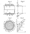
- 1 and 2 1 denotes a shaft with or without a liner and 2 a sleeve, which surrounds the shaft 1 with little play 3.
- the game 3 is depicted in a greatly exaggerated manner, because in reality it is much smaller (in the order of a few tenths or hundredths of a millimeter).
- the center point of bush 2 and unloaded shaft 1 is designated by 0 and the center point of shaft 1 under load F is designated by 0 '.
- the sleeve 2 is provided with a certain number of chambers, for example eight chambers CH 1 to CH 8 according to FIG. 2.
- the carrying liquid for example water
- the carrying liquid is pressurized by means of a pump (not shown in FIGS. 1 and 2) Introduced into the chambers CH 1 to CH 8 via calibrated injection openings O 1 to 0 8 .
- the pressure p 0 has the same value: It is the pressure value that is supplied by the feed pump.
- the pressure p s of the water, which escapes from the game 3 at one or the other end of the bushing has the same value over the entire shaft circumference: it is in the collecting chambers (not shown in FIG 1 and 2) prevailing pressure.
- the value of the pressure p s at the two bush ends can be the same or different, depending on whether the ambient conditions at the two bearing ends are the same or different.
- the pressure p i depends on the size the radial play 3 between shaft 1 and bush 2, which in turn due to the eccentricity varies over the circumference of the shaft 1 and which mainly determines the permeability of the gap; that gap which is flowed through by the water between the region of the openings O 1 to O 8 and one or the other end of the sleeve 2. The smaller the value of the radial gap 3, the greater the value of the pressure p 1 .
- Fig. 3 shows the pressure distribution of the water inside the camp. 3 shows the pressure distribution along the upper surface line of the shaft 1 from the opening O 1 to the right end of the sleeve 2, while the lower diagram part of FIG. 3 shows the pressure distribution along the lower surface line of the shaft 1 of FIG the opening O 5 to the right end of the sleeve 2 shows.
- p l and p 5 the water pressures at the exit of the openings O 1 and . 0 5 denotes.
- the pressure distribution in the left bearing part is the same as that shown in Fig. 3.
- the difference in the area of the triangles A, B, C and A ', B', C ' primarily determines the bearing capacity of the bearing, which balances the load F.
- FIG. 4 is an entropy S / temperature T diagram which illustrates the relaxation of the water in the bearing according to FIGS. 1 and 2.
- Line V represents the evaporation limit of the water.
- Lines P 0 , P 1 , P 5 and P s are isobars which correspond to the pressures p 0 , p 1 , p 5 and p s already mentioned above.
- the water relaxes from the isobar P 0 to the isobar P s according to the vertical line D 1 . If, on the other hand, the water temperature happens to increase from t 1 to t 2 , the vertical relaxation line D 1 changes to D 2 and the water cannot be released to the pressure p s (isobaric P) without at a point E. to cut the vaporization limit V.
- the water evaporates by "flashing" (cavitation) in game 3 before it has reached the right end of the sleeve 2 (and also before it has reached the left end of the sleeve 2, if the value of the pressure p s at this left end is the same as the pressure value at the right end). Since the value of the pressure p l is smaller than that of the pressure p 5 , the water in the game 3 will first evaporate along the upper surface line of the shaft 1 and the steam "plug" thus formed in the gap between the shaft 1 and the bush 2 becomes one Increasing the pressure value p 1 and thus reducing the bearing capacity. This will either result in contact and friction between shaft 1 and bushing 2 in the lower bearing part or bearing instability which will lead to the same result or different bearing damage.
- the pressure p s at one end of the sleeve happens to drop to a value which corresponds, for example, to the isobar P according to FIG. 4, the water will relax, for example along the vertical line D 1 , and in this case intersect the vaporization limit V at a point E ' before the isobaric P ' s is reached; this has the same consequences as mentioned above.
- FIG. 5 elements similar to those in FIGS. 1 and 2 are provided with the same reference symbols.
- 4 with a sleeve is designated, which is mounted on the shaft 1 between a collar 5 and a clamping nut 6.
- injection nozzles are designated, which define the calibrated injection openings 0- to 0 8 .
- 8 is a bearing housing which surrounds the bushing 2 and which is provided with an annular flange 9, by means of which the bearing is fastened to the machine housing 10 by means of screws 11.
- the reference numeral 12 denotes a spherical joint, via which the bush 2 is mounted in the bearing housing 8.
- 13 is a wedge in a groove arranged on the bearing housing and prevents rotation of the sleeve 2.
- With 15, 16 and 17 seals are referred to which are attached to the housing 8 and with the latter and the sleeve 4 collecting chambers 18, 19 and.
- the openings of the injection nozzles 7 and the collecting chambers 18, 19 and 20 are each connected via passages 21, 22, 23 and 24 to a hydraulic circuit, which is designated as a whole by 25; the passages 22, 23 and 24 are formed in the housing 8, the passage 21 in the housing 8 and in the spherical joint 21.
- the circuit 25 can have discharge lines 26, 27 and 28, each of which connects the passages 22, 23 and 24 with a return pump 29, which in turn presses the water into a storage tank 30 via a cooling device 31.
- a feed line 32 with a filter 33 and feed pump 34 arranged therein connects the tank 30 to the passage 21, which is common to all injectors 7.
- the hydraulic circuit 25 can also have various other control and regulating devices, mammometers, pressure accumulators etc. in a known manner. All the bearing elements described so far are well known, which is why a more detailed description is unnecessary.
- a relaxation chamber 35 is now provided on at least one end of the bush 2 in order to minimize the risks of water evaporation in the bearing interior.
- Two possible embodiments of the chamber 35 are shown on the one hand in the upper part and on the other hand in the lower part of FIG. 5, it being understood that in both cases the expansion chamber 35 preferably extends circumferentially over 360 °.
- the chamber 35 is formed by a wall 36, which is located at an axial distance from the end of the sleeve 2 and which extends from the housing 8 to a small distance from the sleeve 4 and thereby recesses an annular gap 37 of weak radial size.
- the sleeve 2 has an axial extension 38 which surrounds the sleeve 4 with a slight radial clearance 37; the relaxation chamber 35 is formed by an annular groove 39 which is provided in the inner peripheral surface of the extension 38 (see also FIG. 6).
- the groove 39 could also be provided in the sleeve 4 according to FIG. 7 or in the shaft 1 if it has a sleeve.
- the flow cross-section of the annular space 37 between the sleeve 4 and the wall 36 or extension 38 is larger than that of the game 3 between the sleeve 4 and the sleeve 2 in order to avoid the wall 36 or the extension 38 works as a warehouse.
- This flow cross-section is calculated in such a way that the water pressure in the expansion chamber 35 is greater than in the adjacent collecting chamber 19.
- the differential pressure between the expansion chamber 35 and the adjacent collecting chamber 19 is low.
- the feared water evaporation occurs when abnormal operating conditions occur (for example a pressure drop in the collecting chamber 19 combined or not with water heating etc.)
- this takes place in the annular space 37 and does not lead to any irregularity in the interior of the bearing, i.e. in game 3 between sleeve 4 and sleeve 2, since the mutual increase in pressure inside the chamber 35 will be homogeneous.
- the chamber 35 behaves so to speak as a pressure accumulator and acts as a buffer between the collecting chamber 19 and the game 3 of the bearing.
- the overpressure between the expansion chamber 35 and the adjacent collecting chamber 19 can also be controlled by a calibrated opening 40, which is optionally provided with a flap, as schematically shown in FIG 41 is shown; such a flap opens like a safety valve if the excess pressure in the expansion chamber 35 becomes too great to conduct a larger volume of steam into the adjacent collecting chamber 19.
- a plurality of relaxation chambers 35 can also be connected in series, for example by providing a second annular groove 39, either in the extension 38, as shown in broken lines in FIG. 6, or in FIG Sleeve 4, or by providing a second wall similar to wall 36 and to be arranged at an axial distance from this wall.
- a relaxation chamber 35 in the form of an annular groove 39 formed in the extension 38 of the sleeve 2 (in which the relaxation in the space 37 between the sleeve 4 and extension 38 obeys a laminar flow law) can be connected in series with one Relaxation chamber 35, which is formed by a wall 36 (and in which the relaxation proceeds according to a turbulent flow law).
- the wall 36 or a plurality thereof can be positively connected to the sleeve 2 instead of to the housing 8.
- the annular groove 39 or a plurality thereof can also be arranged in the inner peripheral surface of a sleeve which is in positive engagement with the housing 8 and encloses the sleeve 4 with little play.
- one or more relaxation chambers are only provided at the right end of the game as described above, it goes without saying that one or more relaxation chambers can also be arranged at the left end of the game if there is a risk of evaporation for the suspension element.
- the invention in contrast to the application described in a hydrostatic bearing, the invention can also be used in hydrodynamic bearings which, although they are less sensitive to evaporation, react in a strictly analogous manner.
- the invention is also applicable to bearings that work with another liquid body as a suspension element, such as ammonia, freon, liquid sodium, etc. —
Landscapes
- Engineering & Computer Science (AREA)
- General Engineering & Computer Science (AREA)
- Mechanical Engineering (AREA)
- Magnetic Bearings And Hydrostatic Bearings (AREA)
Applications Claiming Priority (2)
| Application Number | Priority Date | Filing Date | Title |
|---|---|---|---|
| FR8116454 | 1981-08-28 | ||
| FR8116454A FR2512136A1 (fr) | 1981-08-28 | 1981-08-28 | Palier a fluide liquide |
Publications (1)
| Publication Number | Publication Date |
|---|---|
| EP0074127A1 true EP0074127A1 (de) | 1983-03-16 |
Family
ID=9261742
Family Applications (1)
| Application Number | Title | Priority Date | Filing Date |
|---|---|---|---|
| EP82200878A Withdrawn EP0074127A1 (de) | 1981-08-28 | 1982-07-12 | Flüssigkeitsgeschmiertes Lager |
Country Status (3)
| Country | Link |
|---|---|
| EP (1) | EP0074127A1 (Direct) |
| JP (1) | JPS5842827A (Direct) |
| FR (1) | FR2512136A1 (Direct) |
Cited By (1)
| Publication number | Priority date | Publication date | Assignee | Title |
|---|---|---|---|---|
| US4913563A (en) * | 1988-11-07 | 1990-04-03 | Westinghouse Electric Corp. | Hydrodynamic pivoted pad bearing assembly for a reactor coolant pump |
Citations (4)
| Publication number | Priority date | Publication date | Assignee | Title |
|---|---|---|---|---|
| GB797528A (en) * | 1955-03-16 | 1958-07-02 | Nat Res Dev | Bearings for rotating shafts which are lubricated by gas |
| FR1418179A (fr) * | 1964-10-06 | 1965-11-19 | Commissariat Energie Atomique | Perfectionnement aux paliers à fluide |
| FR2024704A5 (Direct) * | 1969-10-14 | 1970-08-28 | Inst Gidromashinostr | |
| GB1512952A (en) * | 1975-05-22 | 1978-06-01 | Glacier Metal Co Ltd | Journal bearing assembly |
-
1981
- 1981-08-28 FR FR8116454A patent/FR2512136A1/fr active Granted
-
1982
- 1982-07-12 EP EP82200878A patent/EP0074127A1/de not_active Withdrawn
- 1982-08-27 JP JP14785282A patent/JPS5842827A/ja active Pending
Patent Citations (4)
| Publication number | Priority date | Publication date | Assignee | Title |
|---|---|---|---|---|
| GB797528A (en) * | 1955-03-16 | 1958-07-02 | Nat Res Dev | Bearings for rotating shafts which are lubricated by gas |
| FR1418179A (fr) * | 1964-10-06 | 1965-11-19 | Commissariat Energie Atomique | Perfectionnement aux paliers à fluide |
| FR2024704A5 (Direct) * | 1969-10-14 | 1970-08-28 | Inst Gidromashinostr | |
| GB1512952A (en) * | 1975-05-22 | 1978-06-01 | Glacier Metal Co Ltd | Journal bearing assembly |
Cited By (1)
| Publication number | Priority date | Publication date | Assignee | Title |
|---|---|---|---|---|
| US4913563A (en) * | 1988-11-07 | 1990-04-03 | Westinghouse Electric Corp. | Hydrodynamic pivoted pad bearing assembly for a reactor coolant pump |
Also Published As
| Publication number | Publication date |
|---|---|
| FR2512136A1 (fr) | 1983-03-04 |
| FR2512136B1 (Direct) | 1985-03-15 |
| JPS5842827A (ja) | 1983-03-12 |
Similar Documents
| Publication | Publication Date | Title |
|---|---|---|
| DE3620539C2 (Direct) | ||
| DE69007079T2 (de) | Buchse für Ölfilmlager. | |
| EP0023657B1 (de) | Hydrodynamisches Lager | |
| DE1958225C3 (de) | Außeneingriffszahnradpumpe | |
| DE2356817C3 (de) | Selbstdruckerzeugendes Radialgleitlager | |
| DE69102701T2 (de) | Selbstbelastende durchbiegungseinstellwalze. | |
| DE2843658A1 (de) | Oelfilmlager | |
| DE2220847C3 (de) | Hydrostatische Axialkolbenmaschine | |
| DE2252495A1 (de) | Hydro- oder aerostatisches lager | |
| AT390129B (de) | Hydrodynamische gleitlageranordnung fuer drehende lagerzapfen bzw. wellenzapfen | |
| EP0631059B1 (de) | Lager für eine beheizte Walze | |
| DE1775519C3 (de) | Hydrostatisches Axial-Radiallager | |
| EP0105050A1 (de) | Hydrostatische Lagerung | |
| DE2327045A1 (de) | Vorrichtung zum selbsttaetigen berichtigen von abgleichfehlern bei schnellumlaufenden maschinenelementen | |
| EP0064598B1 (de) | Lagersegment für ein hydrodynamisches Gleitlager | |
| AT396262B (de) | Presswalze mit steuerbarer durchbiegung zur behandlung bahnfoermigen gutes, insbesondere zur behandlung einer papierbahn in einer presse oder in einem glaettwerk | |
| EP0038306B1 (de) | Hydrostatisches hydrodynamisches Lager | |
| DE19722870C2 (de) | Gasgeschmierte Gleitringdichtung | |
| EP0074127A1 (de) | Flüssigkeitsgeschmiertes Lager | |
| CH483584A (de) | Vorrichtung zum abgedichteten Überführen einer unter Druck stehenden Flüssigkeit von einem stationären Teil zu einem sich drehenden Teil oder umgekehrt | |
| DE69418620T2 (de) | Radiallager mit gleitschuh und gleitschuh für ein radiallager | |
| DE3522037C2 (Direct) | ||
| CH638590A5 (de) | Hydrostatische kolbenmaschine. | |
| DE931865C (de) | Gleitlager mit kippbaren Bloecken | |
| DE3722436A1 (de) | Hydrostatische dichtung |
Legal Events
| Date | Code | Title | Description |
|---|---|---|---|
| PUAI | Public reference made under article 153(3) epc to a published international application that has entered the european phase |
Free format text: ORIGINAL CODE: 0009012 |
|
| AK | Designated contracting states |
Designated state(s): CH DE GB LI |
|
| STAA | Information on the status of an ep patent application or granted ep patent |
Free format text: STATUS: THE APPLICATION IS DEEMED TO BE WITHDRAWN |
|
| 18D | Application deemed to be withdrawn |
Effective date: 19840225 |
|
| RIN1 | Information on inventor provided before grant (corrected) |
Inventor name: CHABOSEAU, JEAN |