EP0073360A2 - Mowing machine - Google Patents
Mowing machine Download PDFInfo
- Publication number
- EP0073360A2 EP0073360A2 EP82107063A EP82107063A EP0073360A2 EP 0073360 A2 EP0073360 A2 EP 0073360A2 EP 82107063 A EP82107063 A EP 82107063A EP 82107063 A EP82107063 A EP 82107063A EP 0073360 A2 EP0073360 A2 EP 0073360A2
- Authority
- EP
- European Patent Office
- Prior art keywords
- mower
- support beam
- bar
- pivot axis
- articulated
- Prior art date
- Legal status (The legal status is an assumption and is not a legal conclusion. Google has not performed a legal analysis and makes no representation as to the accuracy of the status listed.)
- Granted
Links
Images


Classifications
-
- A—HUMAN NECESSITIES
- A01—AGRICULTURE; FORESTRY; ANIMAL HUSBANDRY; HUNTING; TRAPPING; FISHING
- A01D—HARVESTING; MOWING
- A01D34/00—Mowers; Mowing apparatus of harvesters
- A01D34/01—Mowers; Mowing apparatus of harvesters characterised by features relating to the type of cutting apparatus
- A01D34/412—Mowers; Mowing apparatus of harvesters characterised by features relating to the type of cutting apparatus having rotating cutters
- A01D34/63—Mowers; Mowing apparatus of harvesters characterised by features relating to the type of cutting apparatus having rotating cutters having cutters rotating about a vertical axis
- A01D34/64—Mowers; Mowing apparatus of harvesters characterised by features relating to the type of cutting apparatus having rotating cutters having cutters rotating about a vertical axis mounted on a vehicle, e.g. a tractor, or drawn by an animal or a vehicle
- A01D34/66—Mowers; Mowing apparatus of harvesters characterised by features relating to the type of cutting apparatus having rotating cutters having cutters rotating about a vertical axis mounted on a vehicle, e.g. a tractor, or drawn by an animal or a vehicle with two or more cutters
- A01D34/661—Mounting means
Definitions
- the present invention relates to a mower with a mower bar, which carries at least one rotating mower on its underside and with an articulated on the mower bar and articulated on the headstock, seen in the direction of travel of the machine in its working position, in front of the mower bar and at the same time above the mower bar is arranged.
- Mowing machines of this type which are arranged transversely to the direction of travel of the tractor pulling them, allow a relatively large area to be mowed, depending on the number of mowing tools arranged on the mower bar. After the mowing process has ended, the mower must be brought into a transport position, since it protrudes considerably beyond the width of the tractor, so as not to endanger traffic.
- Swiveling mowing machines which are articulated on a vertical swivel axis which is provided on the trestle approximately in the middle of the tractor.
- the mower is then in its transport position this vertical axis is pivoted backwards so that it comes to rest in the direction of travel of the tractor.
- this position still has the disadvantage that the center of gravity lies far behind the tractor during transport. In extreme cases, this can result in the tractor's front wheels lifting off, especially on bumpy roads.
- a mower has also become known which has a vertical swivel axis to the side of the trestle, so that the mower can be swiveled by approximately 180 ° without projecting significantly beyond the maximum width of the tractor.
- this configuration allows the center of gravity to be moved somewhat closer to the tractor, the disadvantage arises here that the cardan shaft for driving the mowing tools must be removed for the transport position.
- Another mower that has become known has a horizontal pivot axis provided on the side of the headstock, so that the mower can be folded approximately vertically upwards for its transport position. However, it is only arranged to the side of the tractor and still protrudes considerably beyond it.
- the present invention has for its object to provide a mower in which the common center of gravity of the tractor and mower during transport is close to the tractor, in which the drive shaft for driving the mowing tools can remain coupled in any position and the permissible transport width is not is exceeded.
- the support beam is articulated to a vertical pivot axis which is arranged approximately centrally behind the tractor on the headstock, and that the support beam has a horizontal pivot axis approximately in the middle outside the headstock around which the outer part of the support beam can be pivoted upwards together with the cutter bar and that the outer part of the support beam is connected to a hydraulic lifting cylinder, the other end of which is articulated to the headstock.
- the horizontal swivel axis is preferably arranged above the support beam and transversely to it in a carrying bag encompassing the support beam from below.
- an extension piece slides in the outer supporting beam part, on which the mower beam is pivotally attached, while a locking device is arranged in the vicinity of the vertical pivot axis, which has a spring element and a bolt.
- the extendable pull rod of the hydraulic lifting cylinder can be articulated on a bracket arranged vertically on the outer supporting beam part next to the horizontal swivel axis.
- the combined arrangement of a vertical swivel axis in the center of the headstock and a horizontal swivel axis on the support beam outside the three-point hitch results in significant advantages.
- the center of gravity of the mower is closer to the tractor when it is being transported, since it is folded up.
- the PTO shaft can remain coupled in any position, regardless of whether the mower is folded up on the side next to the tractor or folded up behind the tractor in the axial longitudinal direction.
- the mower can be held in any intermediate position between its working position and the transport position, a very steep and upward slope can also be mowed.
- Another advantage is the fact that also with suspended wagon can be worked, since in this case the mower remains in its folded up position to the side of the tractor. In this position, even with the mower folded up, compliance with the permissible transport width determined by the trailer attached is ensured, so that the tractor can be moved with the mower raised and the trailer unhooked.
- the mower By providing an open hydraulic pressure line, the mower can raise itself in its working position with the outer support beam part by a small angle so that it can better follow the unevenness of the ground.
- the arrangement of the carrying bag encompassing the supporting beam from below guides the outer supporting beam part in its working position, which increases the stability.
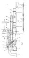
- 1 denotes the headstock that can be attached to the pivot point connection of a tractor.
- the support beam for the cutting tool is divided into three parts, the inner part 3a being articulated on a vertical pivot axis 2, while the outer support beam part 3b is connected to the inner support beam part 3a via a carrying pocket 13 and a horizontal hinge axis 20.
- a tab 10 is fastened, on which the pull rod 12 of a hydraulic lifting cylinder 11 engages.
- the other end of the lifting cylinder is hinged to the headstock.
- an extension piece of the support beam is referred to, which engages in the outer support beam part 3b and there can be locked in any position by means of bolts.
- the extension piece 3c carries a downwardly directed support bracket 22, on which a horizontal shaft 23 is arranged, which engages in the cutter bar 4.
- Mower bar 4 can make small pendulum movements around this shaft 23 in order to better compensate for uneven floors.
- 9 is a conventional drive shaft for the mowing tools, two of which are shown. These have a mowing drum 5, a cutting plate 6 provided with rotating knives as well as a freely rotatable sliding plate 7 and a protective cover 8.
- the drive shaft 9 is rotated in a conventional manner by a gear 24.
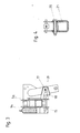
- a locking device is also provided on the supporting beam part 3a, which has a prestressed spiral spring 14 and a spring rod 16 which extends over a deflected chain 15 to a catch pocket 17 shown in more detail in FIG.
- a movable intermediate link 18 is provided, which is held in the catch pocket 17 by a bolt 19.
- FIG. 4 shows a section at the level of the horizontal pivot axis 20 through the support beam, 21 being a guide pocket for the outer support part, which also serves as a stop.
- Mower can be transported in the longitudinal direction behind the tractor, as shown schematically in Figure 5. This ensures that it never exceeds the maximum width of the tractor. In any case, it is ensured that the PTO shaft 9 does not have to be uncoupled, that is to say it can remain coupled both in the working position and in any transport position.
Abstract
Description
Die vorliegende Erfindung betrifft eine Mähmaschine mit einem Mähwerkbalken, der wenigstens ein rotierendes Mähwerkzeug an seiner Unterseite trägt und mit einem gelenkig am Mähwerkbalken und gelenkig am Anbaubock angeordneten Tragbalken, der in Fahrtrichtung der Maschine in ihrer Arbeitsstellung gesehen, vor dem Mähwerkbalken und gleichzeitig oberhalb des Mähwerkbalkens angeordnet ist.The present invention relates to a mower with a mower bar, which carries at least one rotating mower on its underside and with an articulated on the mower bar and articulated on the headstock, seen in the direction of travel of the machine in its working position, in front of the mower bar and at the same time above the mower bar is arranged.
Derartige Mähmaschinen, die quer zur Fahrtrichtung des sie ziehenden Schleppers angeordnet sind, erlauben je nach der Anzahl der am Mähwerkbalken angeordneten Mähwerkzeuge eine relativ große Fläche zu mähen. Nach Beendigung des Mähvorganges muß nun die Mähmaschine, da sie erheblich über die Breite des Schleppers hinausragt, in eine Transportstellung gebracht werden um den Verkehr nicht zu gefährden.Mowing machines of this type, which are arranged transversely to the direction of travel of the tractor pulling them, allow a relatively large area to be mowed, depending on the number of mowing tools arranged on the mower bar. After the mowing process has ended, the mower must be brought into a transport position, since it protrudes considerably beyond the width of the tractor, so as not to endanger traffic.
Es sind bereits schwenkbare Mähmaschinen bekannt, die an einer vertikalen Schwenkachse angelenkt sind, welche am Anbaubock etwa in der Mitte des Schleppers vorgesehen ist. In ihrer Transportstellung wird dann die Mähmaschine um diese vertikale Achse nach hinten geschwenkt, so daß sie in Fahrtrichtung des Schleppers zu liegen kommt. Zwar ragt sie nun nicht mehr über die größten Seitenabmessungen des Schleppers hinaus, jedoch hat diese Stellung noch den Nachteil, daß bei der Transportfahrt der Schwerpunkt weit hinter dem Schlepper liegt. In Extremfällen kann dies zum Abheben der Vorderräder des Schleppers insbesondere bei holprigen Wegen führen.Swiveling mowing machines are already known which are articulated on a vertical swivel axis which is provided on the trestle approximately in the middle of the tractor. The mower is then in its transport position this vertical axis is pivoted backwards so that it comes to rest in the direction of travel of the tractor. Although it no longer protrudes beyond the largest side dimensions of the tractor, this position still has the disadvantage that the center of gravity lies far behind the tractor during transport. In extreme cases, this can result in the tractor's front wheels lifting off, especially on bumpy roads.
Es ist ferner eine Mähmaschine bekannt geworden, die eine vertikale Schwenkachse seitlich vom Anbaubock aufweist, so daß die Mähmaschine um ungefähr 180° verschwenkt werden kann, ohne dabei wesentlich über die maximale Breite des Schleppers hinaus zu ragen. Zwar kann durch diese Ausgestaltung der Schwerpunkt etwas näher zum Schlepper verlegt werden, jedoch tritt hier der Nachteil auf, daß die Gelenkwelle zum Antrieb der Mähwerkzeuge für die Transportstellung abgenommen werden muß.A mower has also become known which has a vertical swivel axis to the side of the trestle, so that the mower can be swiveled by approximately 180 ° without projecting significantly beyond the maximum width of the tractor. Although this configuration allows the center of gravity to be moved somewhat closer to the tractor, the disadvantage arises here that the cardan shaft for driving the mowing tools must be removed for the transport position.
Eine weitere bekannt gewordene Mähmaschine weist eine seitlich vom Anbaubock vorgesehene horizontale Schwenkachse auf, so daß die Mähmaschine für ihre Transportstellung in etwa senkrecht nach oben geklappt werden kann. Dabei ist sie jedoch ausschließlich seitlich vom Schlepper angeordnet und ragt immer noch erheblich über diesen hinaus.Another mower that has become known has a horizontal pivot axis provided on the side of the headstock, so that the mower can be folded approximately vertically upwards for its transport position. However, it is only arranged to the side of the tractor and still protrudes considerably beyond it.
Der vorliegenden Erfindung liegt die Aufgabe zugrunde, eine Mähmaschine zu schaffen, bei der der gemeinsame Schwerpunkt von Schlepper und Mähmaschine bei der Transportfahrt nahe beim Schlepper liegt, bei der die Gelenkwelle zum Antrieb der Mähwerkzeuge in jeder Stellung angekuppelt bleiben kann und wobei die zulässige Transportbreite nicht überschritten wird.The present invention has for its object to provide a mower in which the common center of gravity of the tractor and mower during transport is close to the tractor, in which the drive shaft for driving the mowing tools can remain coupled in any position and the permissible transport width is not is exceeded.
Ausgehend von einer Mähmaschine der eingangs näher genannten Art wird zur Lösung dieser Aufgabe vorgeschlagen, daß der Tragbalken an einer in etwa mittig hinter dem Schlepper am Anbaubock fest angeordneten vertikalen Schwenkachse angelenkt ist, daß der Tragbalken außerhalb des Anbaubocks in etwa seiner Mitte eine horizontale Schwenkachse aufweist um die der äußere Teil des Tragbalkens zusammen mit dem Mähwerkbalken nach oben verschwenkbar ist und daß der äußere Teil des Tragbalkens mit einem hydraulischen Hubzylinder verbunden ist, dessen anderes Ende am Anbaubock angelenkt ist.Starting from a mower of the type mentioned at the outset, it is proposed to solve this problem that the support beam is articulated to a vertical pivot axis which is arranged approximately centrally behind the tractor on the headstock, and that the support beam has a horizontal pivot axis approximately in the middle outside the headstock around which the outer part of the support beam can be pivoted upwards together with the cutter bar and that the outer part of the support beam is connected to a hydraulic lifting cylinder, the other end of which is articulated to the headstock.
Vorzugsweise ist die horizontale Schwenkachse oberhalb des Tragbalkens und quer zu ihr in einer den Tragbalken von unten her umgreifenden Tragtasche angeordnet.The horizontal swivel axis is preferably arranged above the support beam and transversely to it in a carrying bag encompassing the support beam from below.
Bei einem bevorzugten Ausführungsbeispiel gleitet im äußeren Tragbalkenteil ein Verlängerungsstück, an dem der Mähwerkbalken schwenkbar befestigt ist, während in der Nähe der vertikalen Schwenkachse eine Verriegelungsvorrichtung angeordnet ist, die ein Federelement und einen Riegel aufweist.In a preferred embodiment, an extension piece slides in the outer supporting beam part, on which the mower beam is pivotally attached, while a locking device is arranged in the vicinity of the vertical pivot axis, which has a spring element and a bolt.
Die ausfahrbare Zugstange des hydraulischen Hubzylinders kann an einer senkrecht auf dem äußeren Tragbalkenteil neben der horizontalen Schwenkachse angeordneten Lasche angelenkt werden.The extendable pull rod of the hydraulic lifting cylinder can be articulated on a bracket arranged vertically on the outer supporting beam part next to the horizontal swivel axis.
Durch die kombinierte Anordnung einer vertikalen Schwenkachse mittig am Anbaubock und einer horizontalen Schwenkachse am Tragbalken außerhalb des Dreipunktbocks ergeben sich bedeutende Vorteile. Zum einen liegt der Schwerpunkt der Mähmaschine bei Transportfahrt näher am Schlepper, da diese nach oben geklappt ist. Zum anderen kann die Gelenkwelle in jeder Stellung angekuppelt bleiben, gleichgültig ob die Mähmaschine seitlich neben dem Schlepper hochgeklappt ist oder in axialer Längsrichtung hinter dem Schlepper hochgeklappt ist. Des weiteren kann, da die Mähmaschine in jeder beliebigen Zwischenstellung zwischen ihrer Arbeitsstellung und der Transportstellung festgehalten werden kann, auch eine sehr steile und aufwärts geneigte Böschung gemäht werden .The combined arrangement of a vertical swivel axis in the center of the headstock and a horizontal swivel axis on the support beam outside the three-point hitch results in significant advantages. On the one hand, the center of gravity of the mower is closer to the tractor when it is being transported, since it is folded up. On the other hand, the PTO shaft can remain coupled in any position, regardless of whether the mower is folded up on the side next to the tractor or folded up behind the tractor in the axial longitudinal direction. Furthermore, since the mower can be held in any intermediate position between its working position and the transport position, a very steep and upward slope can also be mowed.
Ein weiterer Vorteil ist darin zu sehen, daß auch mit angehängtem Wagen gearbeitet werden kann, da in diesem Fall die Mähmaschine seitlich vom Schlepper in ihrer hochgeklappten Stellung verbleibt. In dieser Stellung ist auch bei hochgeklapptem Mähwerk eine Einhaltung der zulässigen, durch den angehängten Wagen bestimmten Transporrbreite gewährleistet, so daß der Schlepper mit hochgestelltem Mähwerk und ungehängtem Wagen bewegt werdenkann. Durch das Vorsehen einer offenen hydraulischen Druckleitung kann sich die Mähmaschine in ihrer Arbeitsstellung mit dem äußeren Tragbalkenteil um einen kleinen Winkel selbst anheben um so den Bodenunebenheiten besser folgen zu können.Another advantage is the fact that also with suspended wagon can be worked, since in this case the mower remains in its folded up position to the side of the tractor. In this position, even with the mower folded up, compliance with the permissible transport width determined by the trailer attached is ensured, so that the tractor can be moved with the mower raised and the trailer unhooked. By providing an open hydraulic pressure line, the mower can raise itself in its working position with the outer support beam part by a small angle so that it can better follow the unevenness of the ground.
Durch die Anordnung der von unten den Tragbalken umgreifenden Tragtasche wird der äußere Tragbalkenteil in seiner Arbeitsstellung geführt, wodurch die Stabilität erhöht wird.The arrangement of the carrying bag encompassing the supporting beam from below guides the outer supporting beam part in its working position, which increases the stability.
Im folgenden wird die Erfindung anhand der Zeichnung näher erläutert, in der vorteilhafte Ausführungsbeispiele dargestellt sind. Es zeigen:
- Figur 1 eine Seitenansicht der erfindungsgemäßen Mähmaschine in ihrer Arbeitsstellung;
Figur 2 eine Draufsicht auf die Mähmaschine in Arbeitsstellung;
- Figure 1 is a side view of the mower according to the invention in its working position;
- Figure 2 is a plan view of the mower in the working position;
3 und 4 Einzelheiten;3 and 4 details;
5 und 6 zwei verschiedene schematische Transportstellungen.5 and 6 two different schematic transport positions.
In den Figuren ist mit 1 der Anbaubock bezeichnet, der am Drehpunktanschluß eines Schleppers angebaut werden kann. Der Tragbalken für das Mähwerkzeug ist in drei Teile unterteilt, wobei das innere Teil 3a an einer vertikalen Schwenkachse 2 angelenkt ist, während das äußere Tragbalkenteil 3b mitcem inneren Tragbalkenteil 3a über eine Tragtasche 13 und eine horizontale Gelenkachse 20 verbunden ist. In der Nähe der Gelenkachse 20 und senkrecht auf dem Tragbalkenteil 3b ist eine Lasche 10 befestigt , an der die Zugstange 12 eines hydraulischen Hubzylinders 11 angreift. Das andere Ende des Hubzylinders ist am Anbaubock angelenkt.In the figures, 1 denotes the headstock that can be attached to the pivot point connection of a tractor. The support beam for the cutting tool is divided into three parts, the
Mit 3c ist ein Verlängerungsstück des Tragbalkens bezeichnet, das in das äußere Tragbalkenteil 3b angreift und dort mittels Bolzen in einer beliebigen Stellung verriegelbar ist. Das Verlängerungsstück 3c trägt eine nach unten gerichtete Traglasche 22, an der eine waagrechte Welle 23 angeordnet ist, die in dem Mähwerkbalken 4 eingreift. Der Mähwerkbalken 4 kann um diese Welle 23 geringe Pendelbewegungen ausführen um so Bodenunebenheiten besser ausgleichen zu können.With 3c an extension piece of the support beam is referred to, which engages in the outer
In Figur 1 ist ferner mit 9 eine übliche Antriebswelle für die Mähwerkzeuge bezeichnet, von denen zwei dargestellt sind. Diese weisen eine Mähtrommel 5, ein mit rotierenden Messern versehenen Schneidteller 6 sowie einen frei drehbaren Gleitteller 7 auf und eine Schutzverkleidung 8. Die Antriebswelle 9 wird in herkömmlicher Art und Weise von einem Getriebe 24 in Drehungen versetzt.In Figure 1, 9 is a conventional drive shaft for the mowing tools, two of which are shown. These have a
Am Tragbalkenteil 3a ist ferner eine Verriegelungsvorrichtung vorgesehen, die eine unter Vorspannung stehende Spiralfeder 14 und eine Federstange 16 aufweist, welche über eine umgelenkte Kette 15 bis zu einer in Figur 3 näher dargestellten Fangtasche 17 reicht. Am Ende der Kette 15 ist ein bewegliches Zwischenglied 18 vorgesehen, das in der Fangtasche 17 durch einen Riegel 19 festgehalten ist. Diese Verriegelungsvorrichtung ermöglicht es, daß die Mähmaschine beim Anstossen an ein kleines Hindernis um einen geringen Betrag nach hinten verschwenkt wird und nach überwinden des Hindernisses ihre ursprüngliche Arbeitsstellung wieder einnimmt, wie es in Figur 1 und 2 gezeigt ist.A locking device is also provided on the supporting
In den Figuren 1 und 2 ist die Maschine in ihrer Arbeitsstellung dargestellt. Der Hubzylinder 11 ist mit dem Hydraulikanschluß des Schleppers über den Stutzen 25 verbunden, so daß bei Zufuhr von öl die Zugstange 12 eingefahren wird. Dadurch klappt der Tragbalkenteil 3b mit dem Verlängerungsstück 3c und dem Mähwerkbalken 4 samt Mähwerkzeugen senkrecht nach oben, wie es inFigur 1 mit den Positionen 6' und 7' gestrichelt angedeutet ist. In dieser Stellung, die auch in Figur 6 in Hinteransicht gezeigt ist, kann der Schlepper mit hochgeklappter Mähmaschine und angehängtem Wagen bewegt werden. Es ist ferner auch möglich, die Mähmaschine in jeder beliebigen Zwischenstellung zu halten, so daß auch sehr steile Böschungen gemäht werden können. Mit 26 ist ein Hydraulikspeicher am Hubzylinder 11 bezeichnet, der es bei offener Druckleitung ermöglicht, daß sich der Tragbalken mit dem Mähwerkbalken um einen kleinen Winkel selbst anheben kann um so Bodenunebenheiten ausgleichen zu können.In Figures 1 and 2, the machine is working position shown. The
Figur 4 zeigt einen Schnitt auf Höhe der horizontalen Schwenkachse 20 durch&n Tragbalken, wobei mit 21 eine Führungstasche für den äußeren Tragbalkenteil bezeichnet ist, der gleichzeitig als Anschlag dient.FIG. 4 shows a section at the level of the
Durch das Vorsehen der vertikalen Gelenkachse 2 etwa mittig am Anbaubock 1 kann nun auch die hochgeklappte Mähmaschine in Längsrichtung hinter den Schlepper transportiert werden, wie es in Figur 5 schematisch dargestellt ist. Dadurch ist sichergestellt, daß sie an keiner Stelle die Maximalbreite des Schleppers überschreitet. In jedem Fall ist gewährleistet, daß die Gelenkwelle 9 nicht abgekuppelt werden muß, d.h. sowohl in Arbeitsals auch in jeder beliebigen Transportstellung angekuppelt bleiben kann.By providing the
Claims (4)
Priority Applications (1)
| Application Number | Priority Date | Filing Date | Title |
|---|---|---|---|
| AT82107063T ATE16749T1 (en) | 1981-08-31 | 1982-08-04 | MOWER. |
Applications Claiming Priority (2)
| Application Number | Priority Date | Filing Date | Title |
|---|---|---|---|
| DE19813134391 DE3134391A1 (en) | 1981-08-31 | 1981-08-31 | MOWER |
| DE3134391 | 1981-08-31 |
Publications (3)
| Publication Number | Publication Date |
|---|---|
| EP0073360A2 true EP0073360A2 (en) | 1983-03-09 |
| EP0073360A3 EP0073360A3 (en) | 1983-07-20 |
| EP0073360B1 EP0073360B1 (en) | 1985-12-04 |
Family
ID=6140519
Family Applications (1)
| Application Number | Title | Priority Date | Filing Date |
|---|---|---|---|
| EP82107063A Expired EP0073360B1 (en) | 1981-08-31 | 1982-08-04 | Mowing machine |
Country Status (7)
| Country | Link |
|---|---|
| US (1) | US4457127A (en) |
| EP (1) | EP0073360B1 (en) |
| AT (1) | ATE16749T1 (en) |
| CS (1) | CS241120B2 (en) |
| DE (2) | DE3134391A1 (en) |
| PL (1) | PL130623B1 (en) |
| YU (1) | YU195282A (en) |
Cited By (9)
| Publication number | Priority date | Publication date | Assignee | Title |
|---|---|---|---|---|
| DE3444412A1 (en) * | 1984-12-05 | 1986-06-05 | Alois Pöttinger Landmaschinen-Gesellschaft mbH, 8900 Augsburg | Rotary mower |
| DE3444393A1 (en) * | 1984-12-05 | 1986-06-05 | Poettinger Alois Landmasch | Rotary mower |
| EP0184155A1 (en) * | 1984-12-05 | 1986-06-11 | Alois Pöttinger Maschinenfabrik GmbH | Rotary mower |
| EP0503396A1 (en) * | 1991-03-15 | 1992-09-16 | Maschinenfabrik Bernard Krone GmbH | Hay making machine |
| EP0808556A1 (en) * | 1996-05-20 | 1997-11-26 | Maschinenfabrik Bernard Krone GmbH | Suspension and driving arrangement for implements mounted on one or either side of a carrier vehicle |
| EP1131992A1 (en) * | 2000-03-10 | 2001-09-12 | Maschinenfabrik Bernard Krone GmbH | Mowing machine |
| FR2874475A1 (en) * | 2004-09-02 | 2006-03-03 | Noremat Sa | MOWER-CLEANING MACHINE HAVING AN ORIENTATION BLOCK CONTROLLED BY AN ORIENTATION JACK |
| EP2526758A1 (en) * | 2011-05-27 | 2012-11-28 | Maschinenfabrik Bernard Krone GmbH | Mowing machine |
| EP3005853B1 (en) | 2014-10-07 | 2017-04-26 | CLAAS Saulgau GmbH | Agricultural working device and method for operating an agricultural working device |
Families Citing this family (10)
| Publication number | Priority date | Publication date | Assignee | Title |
|---|---|---|---|---|
| JPH0729779Y2 (en) * | 1989-05-17 | 1995-07-12 | 株式会社ササキコーポレーシヨン | Farm work machine |
| US4977734A (en) * | 1989-08-02 | 1990-12-18 | Rowe Carroll G | Foldable hay rake |
| US4974407A (en) * | 1989-11-09 | 1990-12-04 | Rowe Carroll G | Foldable hay rake |
| US6000207A (en) * | 1998-06-09 | 1999-12-14 | Sitrex S.R.L. | Disassemblable hay rake |
| FR2785143B1 (en) * | 1998-10-30 | 2001-02-16 | Kuhn Sa | AGRICULTURAL MACHINE COMPRISING A DOUBLE CYLINDER WITH A SINGLE CYLINDER |
| US6272826B1 (en) | 1999-04-29 | 2001-08-14 | Sitrex S.R.L. | Method and apparatus for positioning a hay rake |
| US6865873B2 (en) * | 2002-06-21 | 2005-03-15 | Sitrex S.R.L. | Pull type V-shaped hay rake |
| US6834488B2 (en) | 2002-11-22 | 2004-12-28 | Sitrex S.R.L. | Towable hay rake with an automatic steering mechanism |
| DE202005021554U1 (en) * | 2005-12-23 | 2008-11-20 | Claas Saulgau Gmbh | mower |
| US11564356B2 (en) * | 2018-03-21 | 2023-01-31 | Johnny E. Grice | Tree branch and brush cutting attachment |
Citations (4)
| Publication number | Priority date | Publication date | Assignee | Title |
|---|---|---|---|---|
| US3308611A (en) * | 1964-01-20 | 1967-03-14 | Mo Trim Inc | Mowing attachment |
| DE2129804A1 (en) * | 1971-06-16 | 1972-12-21 | Krone Bernhard Gmbh Maschf | Mower |
| GB2022382A (en) * | 1978-05-26 | 1979-12-19 | Zweegers P W | Mowing machine |
| FR2432828A1 (en) * | 1978-08-11 | 1980-03-07 | Truax Clarence | PERFECTED MOWER |
Family Cites Families (4)
| Publication number | Priority date | Publication date | Assignee | Title |
|---|---|---|---|---|
| US3070938A (en) * | 1960-06-20 | 1963-01-01 | Shunk Mfg Company | Grass mowers |
| US3757500A (en) * | 1971-10-12 | 1973-09-11 | M Averitt | Multiple unit lawnmower construction |
| NL176039B (en) * | 1973-05-15 | 1984-09-17 | Lely Nv C Van Der | MOWER. |
| GB1515268A (en) * | 1974-04-24 | 1978-06-21 | Clayson Nv | Rotary mowers |
-
1981
- 1981-08-31 DE DE19813134391 patent/DE3134391A1/en not_active Withdrawn
-
1982
- 1982-08-04 EP EP82107063A patent/EP0073360B1/en not_active Expired
- 1982-08-04 DE DE8282107063T patent/DE3267797D1/en not_active Expired
- 1982-08-04 AT AT82107063T patent/ATE16749T1/en not_active IP Right Cessation
- 1982-08-13 US US06/408,019 patent/US4457127A/en not_active Expired - Fee Related
- 1982-08-24 CS CS826170A patent/CS241120B2/en unknown
- 1982-08-30 YU YU01952/82A patent/YU195282A/en unknown
- 1982-08-30 PL PL1982238083A patent/PL130623B1/en unknown
Patent Citations (4)
| Publication number | Priority date | Publication date | Assignee | Title |
|---|---|---|---|---|
| US3308611A (en) * | 1964-01-20 | 1967-03-14 | Mo Trim Inc | Mowing attachment |
| DE2129804A1 (en) * | 1971-06-16 | 1972-12-21 | Krone Bernhard Gmbh Maschf | Mower |
| GB2022382A (en) * | 1978-05-26 | 1979-12-19 | Zweegers P W | Mowing machine |
| FR2432828A1 (en) * | 1978-08-11 | 1980-03-07 | Truax Clarence | PERFECTED MOWER |
Cited By (14)
| Publication number | Priority date | Publication date | Assignee | Title |
|---|---|---|---|---|
| DE3448426C2 (en) * | 1984-12-05 | 1993-11-11 | Poettinger Alois Landmasch | Agricultural machine |
| DE3444412A1 (en) * | 1984-12-05 | 1986-06-05 | Alois Pöttinger Landmaschinen-Gesellschaft mbH, 8900 Augsburg | Rotary mower |
| EP0184155A1 (en) * | 1984-12-05 | 1986-06-11 | Alois Pöttinger Maschinenfabrik GmbH | Rotary mower |
| AT392192B (en) * | 1984-12-05 | 1991-02-11 | Poettinger Ohg Alois | ROTATIONAL MOWING MACHINE |
| DE3444412C2 (en) * | 1984-12-05 | 1992-02-20 | Alois Poettinger Landmaschinen Gmbh, 8910 Landsberg, De | |
| DE3444393A1 (en) * | 1984-12-05 | 1986-06-05 | Poettinger Alois Landmasch | Rotary mower |
| EP0503396A1 (en) * | 1991-03-15 | 1992-09-16 | Maschinenfabrik Bernard Krone GmbH | Hay making machine |
| EP0808556A1 (en) * | 1996-05-20 | 1997-11-26 | Maschinenfabrik Bernard Krone GmbH | Suspension and driving arrangement for implements mounted on one or either side of a carrier vehicle |
| EP1131992A1 (en) * | 2000-03-10 | 2001-09-12 | Maschinenfabrik Bernard Krone GmbH | Mowing machine |
| EP1632129A1 (en) * | 2004-09-02 | 2006-03-08 | Noremat | Brush-cutting mower with an orientation bloc driven by an orientation cylinder |
| FR2874475A1 (en) * | 2004-09-02 | 2006-03-03 | Noremat Sa | MOWER-CLEANING MACHINE HAVING AN ORIENTATION BLOCK CONTROLLED BY AN ORIENTATION JACK |
| EP2526758A1 (en) * | 2011-05-27 | 2012-11-28 | Maschinenfabrik Bernard Krone GmbH | Mowing machine |
| EP3005853B1 (en) | 2014-10-07 | 2017-04-26 | CLAAS Saulgau GmbH | Agricultural working device and method for operating an agricultural working device |
| EP3005853B2 (en) † | 2014-10-07 | 2023-04-19 | CLAAS Saulgau GmbH | Agricultural working device and method for operating an agricultural working device |
Also Published As
| Publication number | Publication date |
|---|---|
| DE3267797D1 (en) | 1986-01-16 |
| DE3134391A1 (en) | 1983-03-10 |
| CS241120B2 (en) | 1986-03-13 |
| YU195282A (en) | 1986-06-30 |
| EP0073360A3 (en) | 1983-07-20 |
| US4457127A (en) | 1984-07-03 |
| ATE16749T1 (en) | 1985-12-15 |
| PL130623B1 (en) | 1984-08-31 |
| PL238083A1 (en) | 1983-04-25 |
| EP0073360B1 (en) | 1985-12-04 |
| CS617082A2 (en) | 1985-07-16 |
Similar Documents
| Publication | Publication Date | Title |
|---|---|---|
| EP0073360B1 (en) | Mowing machine | |
| EP0827684A2 (en) | Self-propelled agricultural harvesting machine | |
| DE3702221A1 (en) | MOWER | |
| DE2053073B2 (en) | mower | |
| DE2715375A1 (en) | AGRICULTURAL WORK EQUIPMENT | |
| DE2917738A1 (en) | MOWER | |
| EP0073359A2 (en) | Locking device for a mowing machine | |
| DE1582356A1 (en) | Mower | |
| DE8016170U1 (en) | DEVICE FOR UROOTING STUMPS | |
| EP0059409A2 (en) | Motor vehicle, in particular an agricultural tractor | |
| DE2800119C3 (en) | Foldable equipment carrier | |
| DE3523632C2 (en) | plow | |
| DE2950121A1 (en) | Close coupled lorry and trailer - have telescopic drawbar with lateral guide under rear of lorry | |
| DE6909386U (en) | DRAWBOOK | |
| DE3034870A1 (en) | Wide working area extending frame agricultural trailer - has folding arms and sliding pivots providing compact unit for transport | |
| EP3266292A1 (en) | Agricultural trailer and traction combination with such a trailer | |
| DE102005018987A1 (en) | Grass mower or snow-clearance cutter fitted to the articulated side-arm projecting from a truck or tractor | |
| DE3148041C2 (en) | ||
| DE2349176B2 (en) | Rake | |
| DE102021102774A1 (en) | Mower arrangement | |
| EP0383013A2 (en) | Farm land roller | |
| DE3224269A1 (en) | Discharge bend for agricultural machines | |
| EP0739582A1 (en) | Rotary tedder | |
| DE3448426C3 (en) | Agricultural machine | |
| DE2928278A1 (en) | Front or rear earthmoving loader - has multiple variously spaced guide rod hinge points for deflecting piece |
Legal Events
| Date | Code | Title | Description |
|---|---|---|---|
| PUAI | Public reference made under article 153(3) epc to a published international application that has entered the european phase |
Free format text: ORIGINAL CODE: 0009012 |
|
| AK | Designated contracting states |
Designated state(s): AT BE CH DE FR GB LI NL |
|
| PUAL | Search report despatched |
Free format text: ORIGINAL CODE: 0009013 |
|
| AK | Designated contracting states |
Designated state(s): AT BE CH DE FR GB LI NL |
|
| 17P | Request for examination filed |
Effective date: 19830715 |
|
| GRAA | (expected) grant |
Free format text: ORIGINAL CODE: 0009210 |
|
| AK | Designated contracting states |
Designated state(s): AT BE CH DE FR GB LI NL |
|
| REF | Corresponds to: |
Ref document number: 16749 Country of ref document: AT Date of ref document: 19851215 Kind code of ref document: T |
|
| ET | Fr: translation filed | ||
| REF | Corresponds to: |
Ref document number: 3267797 Country of ref document: DE Date of ref document: 19860116 |
|
| PGFP | Annual fee paid to national office [announced via postgrant information from national office to epo] |
Ref country code: AT Payment date: 19860728 Year of fee payment: 5 |
|
| PLBE | No opposition filed within time limit |
Free format text: ORIGINAL CODE: 0009261 |
|
| STAA | Information on the status of an ep patent application or granted ep patent |
Free format text: STATUS: NO OPPOSITION FILED WITHIN TIME LIMIT |
|
| 26N | No opposition filed | ||
| PG25 | Lapsed in a contracting state [announced via postgrant information from national office to epo] |
Ref country code: LI Effective date: 19870831 Ref country code: CH Effective date: 19870831 |
|
| PGFP | Annual fee paid to national office [announced via postgrant information from national office to epo] |
Ref country code: NL Payment date: 19870831 Year of fee payment: 6 |
|
| BERE | Be: lapsed |
Owner name: KLOCKNER-HUMBOLDT-DEUTZ A.G. ZWEIGNIEDERLASSUNG F Effective date: 19870831 |
|
| REG | Reference to a national code |
Ref country code: CH Ref legal event code: PL |
|
| GBPC | Gb: european patent ceased through non-payment of renewal fee | ||
| PG25 | Lapsed in a contracting state [announced via postgrant information from national office to epo] |
Ref country code: GB Free format text: LAPSE BECAUSE OF NON-PAYMENT OF DUE FEES Effective date: 19881121 |
|
| PG25 | Lapsed in a contracting state [announced via postgrant information from national office to epo] |
Ref country code: AT Effective date: 19890804 |
|
| PG25 | Lapsed in a contracting state [announced via postgrant information from national office to epo] |
Ref country code: BE Effective date: 19890831 |
|
| PG25 | Lapsed in a contracting state [announced via postgrant information from national office to epo] |
Ref country code: NL Effective date: 19900301 |
|
| NLV4 | Nl: lapsed or anulled due to non-payment of the annual fee | ||
| PG25 | Lapsed in a contracting state [announced via postgrant information from national office to epo] |
Ref country code: FR Effective date: 19900427 |
|
| PG25 | Lapsed in a contracting state [announced via postgrant information from national office to epo] |
Ref country code: DE Effective date: 19900501 |
|
| REG | Reference to a national code |
Ref country code: FR Ref legal event code: ST |