EP0072739A1 - Method of making panels with closed ribs - Google Patents
Method of making panels with closed ribs Download PDFInfo
- Publication number
- EP0072739A1 EP0072739A1 EP82401489A EP82401489A EP0072739A1 EP 0072739 A1 EP0072739 A1 EP 0072739A1 EP 82401489 A EP82401489 A EP 82401489A EP 82401489 A EP82401489 A EP 82401489A EP 0072739 A1 EP0072739 A1 EP 0072739A1
- Authority
- EP
- European Patent Office
- Prior art keywords
- panel
- edges
- rib
- pressing
- folds
- Prior art date
- Legal status (The legal status is an assumption and is not a legal conclusion. Google has not performed a legal analysis and makes no representation as to the accuracy of the status listed.)
- Ceased
Links
Images
Classifications
-
- B—PERFORMING OPERATIONS; TRANSPORTING
- B21—MECHANICAL METAL-WORKING WITHOUT ESSENTIALLY REMOVING MATERIAL; PUNCHING METAL
- B21D—WORKING OR PROCESSING OF SHEET METAL OR METAL TUBES, RODS OR PROFILES WITHOUT ESSENTIALLY REMOVING MATERIAL; PUNCHING METAL
- B21D22/00—Shaping without cutting, by stamping, spinning, or deep-drawing
- B21D22/02—Stamping using rigid devices or tools
- B21D22/027—Stamping using rigid devices or tools for flattening the ends of corrugated sheets
-
- B—PERFORMING OPERATIONS; TRANSPORTING
- B21—MECHANICAL METAL-WORKING WITHOUT ESSENTIALLY REMOVING MATERIAL; PUNCHING METAL
- B21D—WORKING OR PROCESSING OF SHEET METAL OR METAL TUBES, RODS OR PROFILES WITHOUT ESSENTIALLY REMOVING MATERIAL; PUNCHING METAL
- B21D13/00—Corrugating sheet metal, rods or profiles; Bending sheet metal, rods or profiles into wave form
- B21D13/02—Corrugating sheet metal, rods or profiles; Bending sheet metal, rods or profiles into wave form by pressing
Definitions
- the present invention relates to a method of manufacturing ribbed panels, intended to obtain at the end of the ribs a practically straight edge of the panel, allowing the sealed assembly by welding of the panel with a support frame.
- Such a panel can be produced in different ways, the most common of which are folding and stamping.
- Bending consists of making open ribs at their two ends by pressing a flat metal profile between a punch and a die carried by a press brake so as not to stretch the metal, which has the enormous advantage of requiring a extremely low press brake power.
- Stamping consists in pressing the profile between a punch and a die carried by a stamping press so as to produce the closed ribs by a single digging operation with stretching of the metal.
- This process has the advantage of making it possible to produce a perfectly sealed assembly by a quick operation; on the other hand, the power to be used is considerable compared to that required for folding, so this method requires high power manufacturing means, not only very expensive but also more difficult to obtain on the market.
- a panel with open ribs in the shape of a straight U is firstly folded, and, with special tools, the ends are crushed or folded so as to flatten the edges of the panel.
- Another known method consists in pressing the panel between a punch and a die whose complementary profiles ensure the formation of a stamped rib by creep of the metal and connecting to the general surface of the profile, on the edges thereof, by slopes comprising several plies absorbing the excess of stamped material, and therefore forming necking ribs.
- This method has the disadvantage of still making use of the actual stamping for the formation of the necking ribs, and therefore of requiring a press power substantially greater than that required for a simple folding.
- the method of manufacturing panels with closed ribs according to the invention does not have the drawbacks of all the methods known hitherto. It is characterized in that it consists in pressing the sheet to be profiled between a punch and a die whose complementary profiles ensure for each rib a constant development as well as of the ends of each rib with quasi-rectilinear edges by absorption of the difference between said developed and its projection on the horizontal plane by one or more folds whose folds are almost contiguous on the edges of the panel, and perpendicular to the plane of said panel.
- the constant press can over the entire length of each rib, apart from its two ends, be in different known geometric forms (trapezoid, rectangle, half-circumference, etc.).
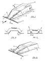
- each rib 2 of the panel 1 has a central portion 3 of regular section and which is connected at each end with the straight edge 4 of the panel by means of a connection profile 5 forming a slope and furnished with two corrugations (6,7) so that the rib opens in a quasi-rectilinear manner, with the clearances of the corrugations 6 and 7 near, on the edge 4 of the panel.
- the developed of the two profiles 2 and 5 are always equal along these, so that the panel of the invention is produced by simple folding and therefore at using very low press brake power.
- the variant of the method of the invention resulting in the form of rib shown in FIG. 4 consists, after obtaining, using the above defined method, ribs as shown diagrammatically in FIG. 1, to carry out an additional operation consisting of, for example using a special tool fitted with one or more pliers, to join the ends of the corrugations 6 and 7 by pressing them at their ends so as to remove the play e.
Abstract
Description
La présente invention concerne un procédé de fabrication de panneaux nervurés, destiné à obtenir en bout des nervures un bord de panneau pratiquement rectiligne, permettant l'assemblage étanche par souduredu panneau avec une ossature de support.The present invention relates to a method of manufacturing ribbed panels, intended to obtain at the end of the ribs a practically straight edge of the panel, allowing the sealed assembly by welding of the panel with a support frame.
Un tel panneau peut être réalisé de différentes façons dont les plus courantes sont le pliage et l'emboutissage.Such a panel can be produced in different ways, the most common of which are folding and stamping.
Le pliage consiste à réaliser des nervures ouvertes à leurs deux extrémités en pressant un profilé métallique plat entre un poinçon et une matrice portés par une presse-plieuse de façon à ne réaliser aucun étirement du métal, ce qui présente l'énorme avantage de nécessiter une puissance de presse plieuse extrêmement faible. Afin de réaliser les panneaux qui nous intéressent, on est ensuite obligé de souder des bouchons métalliques aux deux extrémités de chaque nervure. Ceci présente les inconvénients d'être extrêmement coûteux et d'augmenter sensiblement le poids du panneau.Bending consists of making open ribs at their two ends by pressing a flat metal profile between a punch and a die carried by a press brake so as not to stretch the metal, which has the enormous advantage of requiring a extremely low press brake power. In order to produce the panels that interest us, we are then forced to weld metal plugs at the two ends of each rib. This has the disadvantages of being extremely expensive and significantly increasing the weight of the panel.
L'emboutissage consiste à presser le profilé entre un poinçon et une matrice portés par une presse d'emboutissage de façon à réaliser les nervures fermées par une seule opération d'enfoncement avec étirement du métal. Ce procédé a l'avantage de permettre de réaliser par une opération rapide un assemblage parfaitement étanche ; par contre la puissance à mettre en oeuvre est considérable par rapport à celle nécessitée pour le pliage, de sortecpe ce procédé nécessite des moyens de fabrication de grande puissance, non seulement très coûteux mais en plus difficiles à obtenir sur le marché.Stamping consists in pressing the profile between a punch and a die carried by a stamping press so as to produce the closed ribs by a single digging operation with stretching of the metal. This process has the advantage of making it possible to produce a perfectly sealed assembly by a quick operation; on the other hand, the power to be used is considerable compared to that required for folding, so this method requires high power manufacturing means, not only very expensive but also more difficult to obtain on the market.
Des solutions tendant à pallier les inconvénients de ces procédés classiques ont déjà été proposées, par exemple par les brevets français publiés sous les nOs 2.051.730 et 2.339.449 ainsi que selon le brevet britannique n° 966.747.Solutions tending to overcome the drawbacks of these conventional methods have already been proposed, for example by French patents published under Nos Os 2,051,730 and 2,339,449 as well as according to British patent No. 966,747.
Selon ces procédés connus, on réalise tout d'abord par pliage un panneau à nervures ouvertes en forme de U droit, et, avec un outillage spécial, on en écrase ou plie les extrémités de manière à aplatir les bords du panneau.According to these known methods, a panel with open ribs in the shape of a straight U is firstly folded, and, with special tools, the ends are crushed or folded so as to flatten the edges of the panel.
Il se trouve alors que le raccordement entre la partie écrasée et la partie non écrasée présente une déformation gênante pour l'application ultérieure de revêtement du panneau (peinture ou autre). Enfin, l'écrasement ou le pliage des extrémités des rainures provoque à cet endroit deux pliages en forme de Z écrasé où se forme ensuite inévitablement une oxydation destructrice.It turns out that the connection between the crushed part and the non-crushed part presents an annoying deformation for the subsequent application of panel coating (paint or other). Finally, the crushing or folding of the ends of the grooves causes at this point two folds in the form of a crushed Z where an inevitably destructive oxidation is then formed.
Un autre procédé connu consiste à presser le panneau entre un poinçon et une matrice dont les profils complémentaires assurent la formation d'une nervure emboutie par fluage du métal et se raccordant à la surface générale du profilé, sur les bords de celle-ci, par des pentes comportant plusieurs plis absorbant l'excédent de matière emboutie, et formant donc des nervures de rétreint. Ce procédé présente l'inconvénient de faire tout de même appel à l'emboutissage proprement dit pour la formation des nervures de rétreint, et donc de nécessiter une puissance de presse sensiblement supérieure à celle nécessitée pour un simple pliage.Another known method consists in pressing the panel between a punch and a die whose complementary profiles ensure the formation of a stamped rib by creep of the metal and connecting to the general surface of the profile, on the edges thereof, by slopes comprising several plies absorbing the excess of stamped material, and therefore forming necking ribs. This method has the disadvantage of still making use of the actual stamping for the formation of the necking ribs, and therefore of requiring a press power substantially greater than that required for a simple folding.
Le procédé de fabrication de panneaux à nervures fermées conforme à l'invention ne présente pas les inconvénients de tous les procédés connus jusqu'alors. Il est caractérisé en ce qu'il consiste à presser la feuille à profiler entre un poinçon et une matrice dont les profils complémentaires assurent pour chaque nervure un développé constant ainsi que des extrémités de chaque nervure à bords quasi-rectilignes par absorption de la différence entre ledit développé et sa projection sur le plan horizontal par un ou plusieurs pliages dont les plis sont quasi-jointifs sur les bords du panneau, et perpendiculaires au plan dudit panneau. Le développé constant peut sur toute la longueur de chaque nervure, hormis ses deux extrémités, se présenter sous différentes formes géométriques connues (trapéze, rectangle, demi- circonférence, etc ...).The method of manufacturing panels with closed ribs according to the invention does not have the drawbacks of all the methods known hitherto. It is characterized in that it consists in pressing the sheet to be profiled between a punch and a die whose complementary profiles ensure for each rib a constant development as well as of the ends of each rib with quasi-rectilinear edges by absorption of the difference between said developed and its projection on the horizontal plane by one or more folds whose folds are almost contiguous on the edges of the panel, and perpendicular to the plane of said panel. The constant press can over the entire length of each rib, apart from its two ends, be in different known geometric forms (trapezoid, rectangle, half-circumference, etc.).
L'invention sera mieux comprise à l'aide de la description suivante de deux exemples de réalisation en référence aux dessins annexés dans lesquels :
- - la figure 1 est une vue en perspective d'une des extrémités d'une nervure d'un panneau obtenu par le procédé de l'invention,
- - la figure 2 est une coupe selon la direction AA' de la figure 1,
- - la figure 3 est une vue selon la direction F de la figure 1 du raccordement de la nervure selon le bord du panneau,
- - la figure 4 est une vue d'une nervure obtenue à l'aide d'une variante du procédé de réalisation de l'invention.
- FIG. 1 is a perspective view of one of the ends of a rib of a panel obtained by the method of the invention,
- FIG. 2 is a section along the direction AA ′ in FIG. 1,
- FIG. 3 is a view in direction F of FIG. 1 of the connection of the rib along the edge of the panel,
- - Figure 4 is a view of a rib obtained using a variant of the embodiment of the invention.
En se reportant tout d'abord aux figures 1 à 3, on voit que chaque nervure 2 du panneau 1 présente une partie centrale 3 de section régulière et qui se raccorde à chaque extrémité avec le bord rectiligne 4 du panneau par l'intermédiaire d'un profil de raccordement 5 formant une pente et garni de deux ondulations (6,7) de sorte que la nervure débouche de manière quasi-rectiligne, aux jeux e des ondulations 6 et 7 près, sur le bord 4 du panneau. Par ailleurs, comme indiqué sur les figures 2 et 3, les développés des deux profils 2 et 5 sont toujours égaux tout le long de ceux-ci, de sorte que le panneau de l'invention est réalisé par simple pliage et donc à l'aide d'une puissance de presse-plieuse très faible.Referring first to Figures 1 to 3, we see that each
Si l'on veut réaliser une étanchéité parfaite du bord du panneau, on bouche aisément ensuite par soudure les jeux e laissés par les ondulations 6 et 7 sur le bord 4 du panneau.If one wishes to achieve a perfect seal at the edge of the panel, then the gaps e left by the
La variante du procédé de l'invention aboutissant à la forme de nervure représentée sur la figure 4 consiste, après obtention à l'aide du procédé ci-dessus défini de nervures telles que schématisées sur la figure 1, à réaliser une opération complémentaire consistant, par exemple à l'aide d'un outillage spécial garni d'une ou plusieurs pinces, à rendre jointives les extrémités des ondulations 6 et 7 en pressant celles-ci à leurs extrémités de façon à supprimer les jeux e.The variant of the method of the invention resulting in the form of rib shown in FIG. 4 consists, after obtaining, using the above defined method, ribs as shown diagrammatically in FIG. 1, to carry out an additional operation consisting of, for example using a special tool fitted with one or more pliers, to join the ends of the
Claims (3)
Applications Claiming Priority (2)
| Application Number | Priority Date | Filing Date | Title |
|---|---|---|---|
| FR8115421A FR2510915A1 (en) | 1981-08-07 | 1981-08-07 | PROCESS FOR MANUFACTURING CLOSED RIBBED PANELS |
| FR8115421 | 1981-08-07 |
Publications (1)
| Publication Number | Publication Date |
|---|---|
| EP0072739A1 true EP0072739A1 (en) | 1983-02-23 |
Family
ID=9261311
Family Applications (1)
| Application Number | Title | Priority Date | Filing Date |
|---|---|---|---|
| EP82401489A Ceased EP0072739A1 (en) | 1981-08-07 | 1982-08-06 | Method of making panels with closed ribs |
Country Status (3)
| Country | Link |
|---|---|
| EP (1) | EP0072739A1 (en) |
| FR (1) | FR2510915A1 (en) |
| PT (1) | PT75216B (en) |
Cited By (4)
| Publication number | Priority date | Publication date | Assignee | Title |
|---|---|---|---|---|
| EP0654312A1 (en) * | 1993-11-24 | 1995-05-24 | UMFORMTECHNIK STADE GmbH | Device and method for the forming of corrugated sheets having flat parallel marginal portions |
| EP1276589A1 (en) * | 2000-03-07 | 2003-01-22 | Pullman Industries, Inc. | Vehicle bed edge and manufacturing process |
| WO2006105590A1 (en) * | 2005-04-04 | 2006-10-12 | Fielders Australia Pty Ltd | Trapezoidal steel decking with press-folded ends |
| WO2008079182A1 (en) * | 2006-12-22 | 2008-07-03 | Noble Advanced Technologies, Inc. | Vehicle bed edge construction and manufacturing process therefor |
Citations (6)
| Publication number | Priority date | Publication date | Assignee | Title |
|---|---|---|---|---|
| DE459074C (en) * | 1924-08-10 | 1928-04-26 | E H Hugo Junkers Dr Ing | Process for flattening corrugated iron shafts |
| GB965759A (en) * | 1960-08-08 | 1964-08-06 | Cookson Sheet Metal Dev Ltd | Improvements in or relating to machines for working sheet metal |
| GB966747A (en) * | 1960-05-19 | 1964-08-12 | Cookson Sheet Metal Dev Ltd | Improvements in or relating to machines for working sheet metal |
| FR2051730A1 (en) * | 1969-07-14 | 1971-04-09 | Svenska Flaektfabriken Ab | Stiffening sheet metal ventilator covers |
| FR2339449A1 (en) * | 1976-02-02 | 1977-08-26 | Francon Jean | Corrugated sheet with corrugations closed at ends - is formed between punch and matrix on folding press in single or multiple operation |
| FR2354831A2 (en) * | 1976-06-15 | 1978-01-13 | Francon Jean | Corrugated sheet with corrugations closed at ends - is formed between punch and matrix on folding press in single or multiple operation |
-
1981
- 1981-08-07 FR FR8115421A patent/FR2510915A1/en active Granted
-
1982
- 1982-07-08 PT PT7521682A patent/PT75216B/en unknown
- 1982-08-06 EP EP82401489A patent/EP0072739A1/en not_active Ceased
Patent Citations (6)
| Publication number | Priority date | Publication date | Assignee | Title |
|---|---|---|---|---|
| DE459074C (en) * | 1924-08-10 | 1928-04-26 | E H Hugo Junkers Dr Ing | Process for flattening corrugated iron shafts |
| GB966747A (en) * | 1960-05-19 | 1964-08-12 | Cookson Sheet Metal Dev Ltd | Improvements in or relating to machines for working sheet metal |
| GB965759A (en) * | 1960-08-08 | 1964-08-06 | Cookson Sheet Metal Dev Ltd | Improvements in or relating to machines for working sheet metal |
| FR2051730A1 (en) * | 1969-07-14 | 1971-04-09 | Svenska Flaektfabriken Ab | Stiffening sheet metal ventilator covers |
| FR2339449A1 (en) * | 1976-02-02 | 1977-08-26 | Francon Jean | Corrugated sheet with corrugations closed at ends - is formed between punch and matrix on folding press in single or multiple operation |
| FR2354831A2 (en) * | 1976-06-15 | 1978-01-13 | Francon Jean | Corrugated sheet with corrugations closed at ends - is formed between punch and matrix on folding press in single or multiple operation |
Cited By (9)
| Publication number | Priority date | Publication date | Assignee | Title |
|---|---|---|---|---|
| EP0654312A1 (en) * | 1993-11-24 | 1995-05-24 | UMFORMTECHNIK STADE GmbH | Device and method for the forming of corrugated sheets having flat parallel marginal portions |
| EP1276589A1 (en) * | 2000-03-07 | 2003-01-22 | Pullman Industries, Inc. | Vehicle bed edge and manufacturing process |
| JP2003525802A (en) * | 2000-03-07 | 2003-09-02 | プルマン インダストリーズ, インク. | End of vehicle carrier and method of manufacturing the same |
| EP1276589A4 (en) * | 2000-03-07 | 2004-12-29 | Pullman Ind Inc | Vehicle bed edge and manufacturing process |
| WO2006105590A1 (en) * | 2005-04-04 | 2006-10-12 | Fielders Australia Pty Ltd | Trapezoidal steel decking with press-folded ends |
| GB2439899A (en) * | 2005-04-04 | 2008-01-09 | Fielders Australia Pty Ltd | Trapezoidal steel decking with press-folded ends |
| AU2010100581B4 (en) * | 2005-04-04 | 2010-09-23 | Fielders Australia Pty Ltd | Trapezoidal steel decking with press-folded ends |
| WO2008079182A1 (en) * | 2006-12-22 | 2008-07-03 | Noble Advanced Technologies, Inc. | Vehicle bed edge construction and manufacturing process therefor |
| US7731271B2 (en) | 2006-12-22 | 2010-06-08 | Noble Advanced Technologies, Inc. | Vehicle bed edge construction and manufacturing process therefor |
Also Published As
| Publication number | Publication date |
|---|---|
| FR2510915B1 (en) | 1984-07-06 |
| FR2510915A1 (en) | 1983-02-11 |
| PT75216A (en) | 1982-08-01 |
| PT75216B (en) | 1984-11-19 |
Similar Documents
| Publication | Publication Date | Title |
|---|---|---|
| EP0826943B1 (en) | Assembly for a heat exchanger comprising an aluminium based manifold and tubes and process for manufacturing such an assembly | |
| FR2523483A1 (en) | FLAT FOLDING TOOL | |
| EP1523387A1 (en) | Metal plate, method for making same and method for folding same | |
| FR2461782A1 (en) | SEALING ELEMENT | |
| FR2574704A1 (en) | MACHINE FOR MANUFACTURING SINGLE-SIDE WAVE CARDBOARD | |
| EP0072739A1 (en) | Method of making panels with closed ribs | |
| EP1190786B1 (en) | Method of hydroforming of plates and apparatus for carrying out the same | |
| EP0133401A1 (en) | Connection device between a tube end plate and a header box of a heat exchanger, and method therefor | |
| FR2690870A1 (en) | Honeycomb sandwich panel bending procedure - includes steps of bending honeycomb layer and inner and outer skins separately before sticking together | |
| EP0239490B1 (en) | Spiral heat exchanger and method of making it | |
| FR2572362A1 (en) | CONTAINER AND METHOD FOR CRIMPING EXTREMITIES | |
| EP0038237B1 (en) | Single face corrugating machine | |
| FR2789758A1 (en) | METHOD FOR ASSEMBLING A HEAT EXCHANGER, PARTICULARLY A MOTOR VEHICLE, AND EXCHANGER THUS OBTAINED | |
| FR2656829A1 (en) | SPLITTING SYSTEM IN PARTICULAR FOR CORRUGATED BOARD PLATE. | |
| FR2523742A1 (en) | Rigid brake pedal for motor vehicle - comprises tube bent and pressed to shape for attachment of pedal plate and linkage | |
| EP2145755A1 (en) | Method for forming profiles with an angular section and device for implementing this method | |
| FR2517572A1 (en) | Fixing head of radiator pipe in plate opening - uses relative axial movement of tapered head and gasket sleeve to obtain wedging | |
| EP0844071A1 (en) | Corrugating device | |
| EP0102978B1 (en) | Method for manufacturing pins particularly intended for anchoring in the ground posts or stakes, and pins obtained thereby | |
| FR2570679A1 (en) | BOX ELEMENT OPENING BY ARRACHEMENT, AND METHOD AND INSTALLATION FOR MANUFACTURING THE SAME | |
| WO2005108188A1 (en) | Method of producing a sheet metal part by means of drawing and bending, and corresponding production device, sheet metal part, vehicle cradle, cradle shell and vehicle | |
| EP2157592B1 (en) | Tilting articulated assembly | |
| FR2645796A1 (en) | CONFORMING BODY FOR THE PRODUCTION OF A CLASSIFICATION SHIRT WITH ARTICULATED SHUTTERS WITH AT LEAST ONE FLAP | |
| EP1260656A1 (en) | Casing for reinforcement connection box | |
| FR2553495A1 (en) | MECHANICAL DEVICE FOR ASSEMBLING AND STRENGTHENING PROFILES, AND METHOD FOR ASSEMBLING PROFILES |
Legal Events
| Date | Code | Title | Description |
|---|---|---|---|
| PUAI | Public reference made under article 153(3) epc to a published international application that has entered the european phase |
Free format text: ORIGINAL CODE: 0009012 |
|
| AK | Designated contracting states |
Designated state(s): BE DE FR GB IT NL SE |
|
| 17P | Request for examination filed |
Effective date: 19830317 |
|
| STAA | Information on the status of an ep patent application or granted ep patent |
Free format text: STATUS: THE APPLICATION HAS BEEN REFUSED |
|
| 18R | Application refused |
Effective date: 19851104 |
|
| RIN1 | Information on inventor provided before grant (corrected) |
Inventor name: RENARD, MICHEL |