EP0072518A2 - Bauplattenerstellungsverfahren - Google Patents
Bauplattenerstellungsverfahren Download PDFInfo
- Publication number
- EP0072518A2 EP0072518A2 EP82107185A EP82107185A EP0072518A2 EP 0072518 A2 EP0072518 A2 EP 0072518A2 EP 82107185 A EP82107185 A EP 82107185A EP 82107185 A EP82107185 A EP 82107185A EP 0072518 A2 EP0072518 A2 EP 0072518A2
- Authority
- EP
- European Patent Office
- Prior art keywords
- panel
- load
- building
- angle member
- bearing capacity
- Prior art date
- Legal status (The legal status is an assumption and is not a legal conclusion. Google has not performed a legal analysis and makes no representation as to the accuracy of the status listed.)
- Granted
Links
Images

Classifications
-
- E—FIXED CONSTRUCTIONS
- E04—BUILDING
- E04C—STRUCTURAL ELEMENTS; BUILDING MATERIALS
- E04C2/00—Building elements of relatively thin form for the construction of parts of buildings, e.g. sheet materials, slabs, or panels
- E04C2/30—Building elements of relatively thin form for the construction of parts of buildings, e.g. sheet materials, slabs, or panels characterised by the shape or structure
- E04C2/38—Building elements of relatively thin form for the construction of parts of buildings, e.g. sheet materials, slabs, or panels characterised by the shape or structure with attached ribs, flanges, or the like, e.g. framed panels
- E04C2/386—Building elements of relatively thin form for the construction of parts of buildings, e.g. sheet materials, slabs, or panels characterised by the shape or structure with attached ribs, flanges, or the like, e.g. framed panels with a frame of unreconstituted or laminated wood
-
- E—FIXED CONSTRUCTIONS
- E04—BUILDING
- E04C—STRUCTURAL ELEMENTS; BUILDING MATERIALS
- E04C2/00—Building elements of relatively thin form for the construction of parts of buildings, e.g. sheet materials, slabs, or panels
- E04C2/02—Building elements of relatively thin form for the construction of parts of buildings, e.g. sheet materials, slabs, or panels characterised by specified materials
- E04C2/10—Building elements of relatively thin form for the construction of parts of buildings, e.g. sheet materials, slabs, or panels characterised by specified materials of wood, fibres, chips, vegetable stems, or the like; of plastics; of foamed products
- E04C2/12—Building elements of relatively thin form for the construction of parts of buildings, e.g. sheet materials, slabs, or panels characterised by specified materials of wood, fibres, chips, vegetable stems, or the like; of plastics; of foamed products of solid wood
- E04C2/14—Building elements of relatively thin form for the construction of parts of buildings, e.g. sheet materials, slabs, or panels characterised by specified materials of wood, fibres, chips, vegetable stems, or the like; of plastics; of foamed products of solid wood reinforced
Definitions
- THIS INVENTION relates to a method of a building panel, a method of constructing the panel, a method of constructing a building, and a building.
- one aspect of the present invention provides a method of constructing a panel for use in the construction of a wall of a building, the method comprising the steps of: constructing a panel having an opening therein for a door, window or the like, the portion of the panel lying across the top of the said opening having a predetermined load-bearing capacity; and, where the actual load to be carried by the panel exceeds the said predetermined load-bearing capacity, attaching a reinforcing member to the panel to increase the load-bearing capacity of the said portion of the panel.
- the reinforcing member is an angle member comprising a longitudinal member having a non-linear transverse section.
- the said portion of the panel comprises two generally level vertically spaced-apart beams adapted to lie across the top of the opening in the erected building, and the angle member is attached to the upper of the said two beams.
- a second aspect of the invention provides a panel for use in the construction of a building, the panel being constructed by a method according to the first aspect of the invention.
- a third aspect of the invention provides a panel for use in the construction of a building, the panel comprising: an opening for a door, window or the like; a portion lying across the top of the opening (when the panel is in an erected orientation), the said portion having a low load-bearing capacity; and a reinforcing member attached to the said portion to increase the load-bearing capacity of the said portion.
- a fourth aspect of the invention provides a method of constructing a building from a plurality of pre-fabricated panels, at least some of which panels comprise openings for doors, windows and the like, the top of each opening being bounded by a portion of the panel having a pre-determined load-bearing capacity, the method comprising the steps of assembling the panels in a desired arrangement and re-inforcing the said portions of the panels only where the load to be carried by that portion exceeds the respective said load-bearing capacity.
- a fifth aspect of the invention provides a building constructed from panels according to the second or third aspects of the invention or by a method according to the fourth aspect.
- the lintel shown in Figure 1 comprises two wooden beams 1, 2 running horizontally across the top of the door or window opening (hereinafter referred to as “the opening"), the wider side of each beam lying in a substantially horizontal plane. These two horizontal beams 1, 2 are spaced vertically from one another by two further beams 3, 4 (herein referred to as “vertical beams”), which run horizontally across the top of the opening but which have their wider sides arranged to lie in substantially vertical planes.
- Such a lintel can be arranged to have a considerable load-bearing capacity.
- a plywood sheathing 5 is commonly applied to the outside of the panel surrounding the opening in order to conceal the construction of the lintel.
- Figure 2 illustrates a preferred method of construction of a lintel in accordance with the invention. It can be seen that the two horizontal beams 1, 2 shown in Figure 1 are present, but that the two vertical beams 3,4 are absent. The two horizontal beams 1, 2 are spaced vertically apart from one another by means of horizontally spaced members 6, which can be seen more clearly in Figure 3.
- This form of construction is less strong than the known construction illustrated in Figure 1, and, unless the components of the panel were individually to be strong, the panel could not be used in a position where it was required to bear a significant load. The panel thus has a low load-bearing capacity.
- a steel angle member 7 having an "L” section and orientated with the "L” inverted is added to the panel, before the plywood sheathing 5 is applied to form a lintel.
- the short leg of the "L” of the angle member 7 lies along the top surface of the upper 1 of the two horizontal beams 1, 2 and the longer leg of the "L” from the upper horizontal beam 1 to cover the outside face of the upper beam 1.
- the downward extent of the longer leg of the "L” may be sufficient to cover the outside face of the lower horizontal beam 2.
- the angle member 7 is wide enough for each end to be supported by a respective one of the side pillars 8 which define the lateral extent of the opening.
- the panel is constructed in a factory and is shipped to the construction site before the angle member is added.
- the addition of the angle member is carried out on site only on the panels which are to bear a load, and the waste of using load-bearing lintels where they are not necessary is avoided.
- a convenient way to attach the angle member 7 to the panel is by means of nails passing through the angle member 7 (commonly at 400 or 600 mm centres) into the horizontal beams 1 and 2, the upright members 6 and the side pillars 8.
- the positions of the nails 9 are illustrated schematically in Figure 3.
- the vertical members 6 may be dispensed with, the separation of the upper and lower horizontal beams 1, 2 then being achieved by the attachment of these two beams to the upright pillars 8 ; in which case substantially vertical stiffening ribs (not shown) may be provided throughout the length of the longer leg of the angle member 7.
- the angle member 7 may be of relatively light construction.
- the usual plywood sheathing 5 is applied to the finished article to cover the angle member 7 and thus, as in the known construction illustrated in Figure 1, serves to conceal the manner of construction of the lintel. It will be appreciated that the sheathing 5 is therefore added on site and not in the pre-fabricating factory.
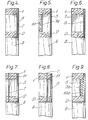
- FIGS. 4 to 9 illustrate alternative forms of construction of a lintel in accordance with the invention, in which the location and form of the angle member 7 are varied. A brief description of each Figure will suffice for the man skilled in the art to appreciate the mode of construction.
- the angle member 7 is the same as the angle member 7 illustrated in Figure 2, but is applied over the plywood sheathing 5 and thus at least some of the nails 8 which attach the angle member 7 to the panel will pass through the plywood sheathing. Therefore, in this embodiment, and in those shown in Figures 5-9, the sheathing may be applied in the factory if desired.
- Figure 5 illustrates a mode of construction employing a modified angle member 7a provided with two angles to form a channel-section member.
- a further modification consists of the modified angle member 7a lying between the upper and lower horizontal beams 1, 2 and embracing a relatively small vertical beam 10.
- the channel of the angle member 7a faces inwards.
- the vertical beam 10 in this form of construction is not equivalent to either of the two vertical beams 3, 4 illustrated in Figure 1, since there is no great load-bearing capacity in the construction shown in Figure 5 unless the angle member 7a is present.
- Figure 6 shows a form of construction in which the angle member 7 is once again the same as the angle member 7 illustrated in Figure 2, but in this form of construction the angle member 7 is located with the longer leg of the "L” on the inside of the panel instead of on the outside. The shorter leg of the "L” remains on top of the upper horizontal beam 1, and the plywood sheathing 5 is applied to the panel in the conventional manner.
- Figures 7 and 8 illustrate further modifications in which a saw kerf 11 (in other words a pre-made saw cut) is provided in the upper horizontal beam 1, the kerf 11 running along substantially the entire span of the upper horizontal beam 1 across the opening.
- the angle member 7 is the same as in Figure 2 and the shorter leg of the "L” lies on top of the upper horizontal beam 1.
- the longer leg of the "L” passes downwards through the kerf 11 into the space between the upper horizontal beam 1 and the lower horizontal beam 2.
- Figure 9 illustrates a modified form of construction similar to that shown in Figure 5, in that the angle member 7a is in the form of a channel-section member, is located between the upper horizontal beam 1 and lower horizontal beam 2 and embraces a relatively small vertical beam 10a.
- the channel of the angle member 7 faces outwardly and the small vertical beam 10a is adjacent the inside face of the plywood sheathing 5.
- the panel has a low load-bearing capacity in the absence of the angle member 7 or 7a, and thus, since the angle member is inserted only where a load-bearing capacity is required, cost savings can be made.
Landscapes
- Engineering & Computer Science (AREA)
- Architecture (AREA)
- Life Sciences & Earth Sciences (AREA)
- Wood Science & Technology (AREA)
- Civil Engineering (AREA)
- Structural Engineering (AREA)
- Load-Bearing And Curtain Walls (AREA)
- Conveying And Assembling Of Building Elements In Situ (AREA)
- Panels For Use In Building Construction (AREA)
Priority Applications (1)
| Application Number | Priority Date | Filing Date | Title |
|---|---|---|---|
| AT82107185T ATE19278T1 (de) | 1981-08-12 | 1982-08-09 | Bauplattenerstellungsverfahren. |
Applications Claiming Priority (2)
| Application Number | Priority Date | Filing Date | Title |
|---|---|---|---|
| GB8124655 | 1981-08-12 | ||
| GB8124655 | 1981-08-12 |
Publications (3)
| Publication Number | Publication Date |
|---|---|
| EP0072518A2 true EP0072518A2 (de) | 1983-02-23 |
| EP0072518A3 EP0072518A3 (en) | 1983-03-23 |
| EP0072518B1 EP0072518B1 (de) | 1986-04-16 |
Family
ID=10523896
Family Applications (1)
| Application Number | Title | Priority Date | Filing Date |
|---|---|---|---|
| EP82107185A Expired EP0072518B1 (de) | 1981-08-12 | 1982-08-09 | Bauplattenerstellungsverfahren |
Country Status (3)
| Country | Link |
|---|---|
| EP (1) | EP0072518B1 (de) |
| AT (1) | ATE19278T1 (de) |
| DE (1) | DE3270627D1 (de) |
Cited By (1)
| Publication number | Priority date | Publication date | Assignee | Title |
|---|---|---|---|---|
| AU735942B2 (en) * | 1998-11-27 | 2001-07-19 | Mitek Holdings, Inc. | A lintel, a lintel side plate and a method of forming a lintel |
Family Cites Families (2)
| Publication number | Priority date | Publication date | Assignee | Title |
|---|---|---|---|---|
| US2066253A (en) * | 1935-09-24 | 1936-12-29 | American Cyanamid & Chem Corp | Lintel |
| GB1417190A (en) * | 1971-12-21 | 1975-12-10 | Turner A R | Wall framing |
-
1982
- 1982-08-09 EP EP82107185A patent/EP0072518B1/de not_active Expired
- 1982-08-09 DE DE8282107185T patent/DE3270627D1/de not_active Expired
- 1982-08-09 AT AT82107185T patent/ATE19278T1/de not_active IP Right Cessation
Cited By (1)
| Publication number | Priority date | Publication date | Assignee | Title |
|---|---|---|---|---|
| AU735942B2 (en) * | 1998-11-27 | 2001-07-19 | Mitek Holdings, Inc. | A lintel, a lintel side plate and a method of forming a lintel |
Also Published As
| Publication number | Publication date |
|---|---|
| DE3270627D1 (en) | 1986-05-22 |
| EP0072518B1 (de) | 1986-04-16 |
| ATE19278T1 (de) | 1986-05-15 |
| EP0072518A3 (en) | 1983-03-23 |
Similar Documents
| Publication | Publication Date | Title |
|---|---|---|
| US5333426A (en) | Wood frame construction system with prefabricated components | |
| CA2285890C (en) | Shear wall panel | |
| US3738083A (en) | Prefabricated house | |
| US4937993A (en) | Composite building panel | |
| US6892498B1 (en) | Interlocking construction system | |
| US3999338A (en) | Roof framework employing slotted gable construction | |
| US5551200A (en) | Elongated integral truss brace | |
| US5095671A (en) | Framework of a building | |
| KR870001888B1 (ko) | 조립식 건축물 | |
| US5617700A (en) | Prefabricated building panel | |
| US4432184A (en) | Support for the construction of buildings | |
| FI70965B (fi) | Timmerelement och av timmerelementen tillverkad vaegg | |
| EP0072518A2 (de) | Bauplattenerstellungsverfahren | |
| US2882557A (en) | Prefabricated house panels and method of assembling them | |
| US5718093A (en) | Floor panel joint structure and method of making a wooden building with the same | |
| CA2047931A1 (en) | Prefabricated unit building wall | |
| DE69325464T2 (de) | Modulare gebäudestruktur aus laminatplatten | |
| WO2001029338A2 (en) | Shear wall panel | |
| EP1292738B1 (de) | Blockhaus und baurundholz | |
| DE19916247A1 (de) | Baukastensystem für Fertighäuser | |
| JP3902847B2 (ja) | バルコニー付きユニット建物 | |
| DE69510027T2 (de) | Modulare Häusen | |
| FI83119B (fi) | Yttervaeggelement. | |
| JPH0772064B2 (ja) | エレベーター用鉄塔昇降路 | |
| WO2001051725A1 (en) | Method of building wall framework, wall framework, and wood profile |
Legal Events
| Date | Code | Title | Description |
|---|---|---|---|
| PUAI | Public reference made under article 153(3) epc to a published international application that has entered the european phase |
Free format text: ORIGINAL CODE: 0009012 |
|
| PUAL | Search report despatched |
Free format text: ORIGINAL CODE: 0009013 |
|
| AK | Designated contracting states |
Designated state(s): AT BE CH DE FR GB IT LI LU NL SE |
|
| AK | Designated contracting states |
Designated state(s): AT BE CH DE FR GB IT LI LU NL SE |
|
| 17P | Request for examination filed |
Effective date: 19830916 |
|
| GRAA | (expected) grant |
Free format text: ORIGINAL CODE: 0009210 |
|
| AK | Designated contracting states |
Kind code of ref document: B1 Designated state(s): AT BE CH DE FR GB IT LI LU NL SE |
|
| PG25 | Lapsed in a contracting state [announced via postgrant information from national office to epo] |
Ref country code: NL Effective date: 19860416 Ref country code: LI Effective date: 19860416 Ref country code: IT Free format text: LAPSE BECAUSE OF FAILURE TO SUBMIT A TRANSLATION OF THE DESCRIPTION OR TO PAY THE FEE WITHIN THE PRESCRIBED TIME-LIMIT;WARNING: LAPSES OF ITALIAN PATENTS WITH EFFECTIVE DATE BEFORE 2007 MAY HAVE OCCURRED AT ANY TIME BEFORE 2007. THE CORRECT EFFECTIVE DATE MAY BE DIFFERENT FROM THE ONE RECORDED. Effective date: 19860416 Ref country code: FR Free format text: THE PATENT HAS BEEN ANNULLED BY A DECISION OF A NATIONAL AUTHORITY Effective date: 19860416 Ref country code: CH Effective date: 19860416 Ref country code: BE Effective date: 19860416 Ref country code: AT Effective date: 19860416 |
|
| REF | Corresponds to: |
Ref document number: 19278 Country of ref document: AT Date of ref document: 19860515 Kind code of ref document: T |
|
| PG25 | Lapsed in a contracting state [announced via postgrant information from national office to epo] |
Ref country code: SE Effective date: 19860430 |
|
| REF | Corresponds to: |
Ref document number: 3270627 Country of ref document: DE Date of ref document: 19860522 |
|
| REG | Reference to a national code |
Ref country code: CH Ref legal event code: PL |
|
| PG25 | Lapsed in a contracting state [announced via postgrant information from national office to epo] |
Ref country code: LU Free format text: LAPSE BECAUSE OF NON-PAYMENT OF DUE FEES Effective date: 19860831 |
|
| EN | Fr: translation not filed | ||
| NLV1 | Nl: lapsed or annulled due to failure to fulfill the requirements of art. 29p and 29m of the patents act | ||
| PLBE | No opposition filed within time limit |
Free format text: ORIGINAL CODE: 0009261 |
|
| 26N | No opposition filed | ||
| PG25 | Lapsed in a contracting state [announced via postgrant information from national office to epo] |
Ref country code: GB Free format text: LAPSE BECAUSE OF NON-PAYMENT OF DUE FEES Effective date: 19880809 |
|
| PG25 | Lapsed in a contracting state [announced via postgrant information from national office to epo] |
Ref country code: DE Effective date: 19890503 |
|
| GBPC | Gb: european patent ceased through non-payment of renewal fee |