EP0072323B1 - Composants munis d'un dispositif d'absorption d'énergie par déformation plastique et/ou de limitation d'effort, et trains d'atterrissage d'aérodynes équipés de tels composants - Google Patents
Composants munis d'un dispositif d'absorption d'énergie par déformation plastique et/ou de limitation d'effort, et trains d'atterrissage d'aérodynes équipés de tels composants Download PDFInfo
- Publication number
- EP0072323B1 EP0072323B1 EP82401479A EP82401479A EP0072323B1 EP 0072323 B1 EP0072323 B1 EP 0072323B1 EP 82401479 A EP82401479 A EP 82401479A EP 82401479 A EP82401479 A EP 82401479A EP 0072323 B1 EP0072323 B1 EP 0072323B1
- Authority
- EP
- European Patent Office
- Prior art keywords
- rod
- cylinder
- jack
- bracing
- shaft
- Prior art date
- Legal status (The legal status is an assumption and is not a legal conclusion. Google has not performed a legal analysis and makes no representation as to the accuracy of the status listed.)
- Expired
Links
- 239000004033 plastic Substances 0.000 title claims description 61
- 238000010521 absorption reaction Methods 0.000 claims description 75
- 238000005096 rolling process Methods 0.000 claims description 52
- 210000000078 claw Anatomy 0.000 claims description 20
- 238000006073 displacement reaction Methods 0.000 claims description 19
- 230000000717 retained effect Effects 0.000 claims description 16
- 230000000903 blocking effect Effects 0.000 claims description 4
- 239000010720 hydraulic oil Substances 0.000 claims description 4
- 230000005226 mechanical processes and functions Effects 0.000 claims description 4
- 238000013016 damping Methods 0.000 claims description 2
- 230000035939 shock Effects 0.000 description 40
- 239000006096 absorbing agent Substances 0.000 description 33
- 230000006835 compression Effects 0.000 description 18
- 238000007906 compression Methods 0.000 description 18
- 230000008901 benefit Effects 0.000 description 11
- 239000003921 oil Substances 0.000 description 7
- 230000021715 photosynthesis, light harvesting Effects 0.000 description 7
- 230000000670 limiting effect Effects 0.000 description 6
- 230000007246 mechanism Effects 0.000 description 6
- 230000001960 triggered effect Effects 0.000 description 6
- 230000000694 effects Effects 0.000 description 5
- 239000000463 material Substances 0.000 description 5
- 238000007789 sealing Methods 0.000 description 5
- 125000006850 spacer group Chemical group 0.000 description 5
- 230000002159 abnormal effect Effects 0.000 description 3
- 230000009172 bursting Effects 0.000 description 3
- 239000007789 gas Substances 0.000 description 3
- 235000019589 hardness Nutrition 0.000 description 3
- 230000036961 partial effect Effects 0.000 description 3
- IJGRMHOSHXDMSA-UHFFFAOYSA-N Atomic nitrogen Chemical compound N#N IJGRMHOSHXDMSA-UHFFFAOYSA-N 0.000 description 2
- 230000005489 elastic deformation Effects 0.000 description 2
- 239000012528 membrane Substances 0.000 description 2
- 230000003068 static effect Effects 0.000 description 2
- 101100224579 Caenorhabditis elegans dre-1 gene Proteins 0.000 description 1
- 244000043261 Hevea brasiliensis Species 0.000 description 1
- 238000004891 communication Methods 0.000 description 1
- 239000002361 compost Substances 0.000 description 1
- 239000000470 constituent Substances 0.000 description 1
- 230000003247 decreasing effect Effects 0.000 description 1
- 230000006866 deterioration Effects 0.000 description 1
- 238000009826 distribution Methods 0.000 description 1
- 229920001971 elastomer Polymers 0.000 description 1
- 239000000806 elastomer Substances 0.000 description 1
- 238000003197 gene knockdown Methods 0.000 description 1
- 230000003100 immobilizing effect Effects 0.000 description 1
- 238000010030 laminating Methods 0.000 description 1
- 238000004519 manufacturing process Methods 0.000 description 1
- 229920003052 natural elastomer Polymers 0.000 description 1
- 229920001194 natural rubber Polymers 0.000 description 1
- 229910052757 nitrogen Inorganic materials 0.000 description 1
- 229920001296 polysiloxane Polymers 0.000 description 1
- 238000004321 preservation Methods 0.000 description 1
- 230000000750 progressive effect Effects 0.000 description 1
- 238000010926 purge Methods 0.000 description 1
- 230000002829 reductive effect Effects 0.000 description 1
- 230000004044 response Effects 0.000 description 1
- 230000002441 reversible effect Effects 0.000 description 1
- 238000004904 shortening Methods 0.000 description 1
- 230000004083 survival effect Effects 0.000 description 1
- 239000000725 suspension Substances 0.000 description 1
- 239000002562 thickening agent Substances 0.000 description 1
- 238000011144 upstream manufacturing Methods 0.000 description 1
Images


Classifications
-
- B—PERFORMING OPERATIONS; TRANSPORTING
- B64—AIRCRAFT; AVIATION; COSMONAUTICS
- B64C—AEROPLANES; HELICOPTERS
- B64C25/00—Alighting gear
- B64C25/32—Alighting gear characterised by elements which contact the ground or similar surface
- B64C25/58—Arrangements or adaptations of shock-absorbers or springs
- B64C25/60—Oleo legs
-
- F—MECHANICAL ENGINEERING; LIGHTING; HEATING; WEAPONS; BLASTING
- F16—ENGINEERING ELEMENTS AND UNITS; GENERAL MEASURES FOR PRODUCING AND MAINTAINING EFFECTIVE FUNCTIONING OF MACHINES OR INSTALLATIONS; THERMAL INSULATION IN GENERAL
- F16F—SPRINGS; SHOCK-ABSORBERS; MEANS FOR DAMPING VIBRATION
- F16F7/00—Vibration-dampers; Shock-absorbers
- F16F7/12—Vibration-dampers; Shock-absorbers using plastic deformation of members
- F16F7/125—Units with a telescopic-like action as one member moves into, or out of a second member
Definitions
- the present invention relates to components provided with a device for absorbing energy by plastic deformation and / or limiting force, as well as landing gear of aerodynes equipped with such components.
- the invention relates to hydraulic and / or mechanical components, such as actuator, shock absorber and strut, intended for the equipment of helicopter landing gear, in order to give latter cases a capacity commonly referred to as "anti-crash".
- the rolling elements are maintained in predetermined positions in perforations formed in a sleeve, mounted coaxially between the telescopic members, of generally cylindrical shape, and suitable for moving with these rolling elements and for maintain a predetermined spacing between them during their rolling resulting from a relative displacement of the telescopic members, so that this sleeve acts as a cage for the rolling elements.
- the mounting of the rolling elements clamped between the telescopic members is chosen to compressively compress these rolling elements between portions, most often cylindrical, of the telescopic members, so that these rolling elements exert, in the contact zone with telescopic members, an average contact pressure of value greater than the deformation contact pressure for the material constituting at least the deformable telescopic member, that is to say at the pressure for which establishes a distribution of the stresses leading to plastic deformation in the contact zone, this plastic deformation producing a high and localized energy dissipation.
- the value of the energy dissipation per unit of displacement of the telescopic members depends on the degree or the depth of the plastic deformation, which itself depends on the load of the rolling elements, i.e. their number , of the degree of tightening, defined from the value whose radial dimension or diameter of the rolling elements is greater than the difference between the radial dimensions or external and internal radii of the telescopic members in the contact zone before deformation.
- This velocity of energy dissipation also depends on the relative hardness of the materials constituting the rolling elements and the telescopic members.
- the use of such devices provides energy absorption characteristics which can be predicted with great precision.
- one or both of the telescopic members is produced with an internal or external dimension which varies continuously, so as to obtain a convergent or divergent part for example so that the rolling elements meet resistance. respectively increasing or decreasing during a telescopic movement of the members.
- the wall thickness of one of the two members can vary along the latter to present a variable resistance to plastic deformation.
- a steering shaft comprising two parts mounted telescopically one inside the other and integral in rotation by pins simultaneously ensuring the axial positioning of these two parts in a relative position of normal operation, is rotatably mounted in a support envelope consisting of a lower tubular portion, integral with the chassis of the vehicle, and mounted telescopically in a portion upper tubular, connected to the dashboard by a unidirectional breaking fitting by means of pins.
- a support envelope consisting of a lower tubular portion, integral with the chassis of the vehicle, and mounted telescopically in a portion upper tubular, connected to the dashboard by a unidirectional breaking fitting by means of pins.
- energy absorption devices are also known, the structure of which has many analogies with those of the devices previously considered, since they include printing means, also presenting in the form of balls, rollers, etc., but also in the form of a ring, means intended to effect a relative displacement of said printing means and of an energy absorbing member, appearing under the shape of a sleeve.
- the means intended to effect a relative displacement comprises a support member, facing the energy absorption member, and carrying, by example in a radial chamber having at least one conical wall facing the latter, the printing means, so that the latter accompany the movement of the support member relative to the energy absorption member, and are repelled in this last.
- the energy absorption member is a deformable member which is elastically qualified as an elastomer member in this patent FR-A-2 110 078 , and arranged so as to undergo localized elastic deformation by compression as well as elastic compression and elongation distributed laterally with respect to the localized elastic deformation zone.
- the energy absorption member constituted by a sleeve having elastomeric qualities, and produced in particular from natural rubbers or silicone, allows the production of a device providing the advantages of a hydraulic or pneumatic damper, since the shocks and jolts can be absorbed, while presenting only a structure of cost price and reduced weight.
- aircraft landing gear is equipped with various components, such as jacks, shock absorbers and struts, which fulfill a main hydraulic and / or mechanical function, and which each comprise a tubular element inside which is received a telescopic element, immobilized with respect to the tubular element in at least one position of normal use of the component, by at least one locking device.
- components such as jacks, shock absorbers and struts, which fulfill a main hydraulic and / or mechanical function, and which each comprise a tubular element inside which is received a telescopic element, immobilized with respect to the tubular element in at least one position of normal use of the component, by at least one locking device.
- the internal locking mechanism comprises elastic claws carried by the piston or cylinder of the jack, a locking step carried respectively by the cylinder or the piston of the jack, and a locking piston, sliding respectively in the cylinder or around the rod. , and resiliently returned to the claw locking position when they are blocked behind the step.
- This locking mechanism is hydraulically released, because the locking piston is pushed back against the return spring by the actuating pressure of the jack, because the spring chamber is in communication with the jack chamber in which reigns the lowest pressure.
- the problem underlying the invention consists in taking advantage of any possibility of relative travel between the rod and the cylinder of such a jack, in order to ensure absorption and dissipation of energy which allows the jack to not transmit to the structure of the aerodyne that an admissible fraction of the too high load which requests it, under abnormal conditions of use.
- the present invention aims to adapt energy absorption mechanisms by plastic deformation, of the type described in FR-A-1 549 884 and its addition FR-A-2 010 302, in filling components.
- a main hydraulic and / or mechanical function such as an actuating and / or bracing cylinder, of the type described in DE-A-2 313 821, or an oleopneumatic damper, which already constitutes by itself a device for absorption and dissipation of energy, or a bracing strut of a main element, so that these components can fulfill an additional function of energy absorption and / or limitation of effort, for a purpose security and protection of a structure with which they are associated, and comprising parts to which violent forces, resulting from shocks and jolts applied to the structure, must not be transmitted without damping, attenuation or limitation.
- the invention also aims to design landing gear for aerodynes, in particular helicopter landing machines, equipped with components according to the invention, and having an “anti-crash” capacity.
- a component according to the invention fulfilling a main hydraulic and / or mechanical function, of the jack, damper or strut type, and comprising a tubular element inside which is received a telescopic element immobilized vis-à-vis screw of the tubular element in at least one position of use by at least one locking device, is characterized in that it also comprises a device for absorbing energy by plastic deformation and / or limiting force, comprising a set of rolling elements held by a cage and interposed with clamping between an internal member and an external member mounted one inside the other, and of which at least the external member is a member with deformation load predetermined plastic, said members being capable of sliding into one another after rupture of a frangible element with predetermined breaking load and included in the locking device, so that the rolling elements pro evoke, in a manner so known, energy dissipation by plastic deformation of at least the external member, which is integral with the tubular element, the telescopic element constituting the internal member which drives the cage for retaining the
- a component of the cylinder type according to the invention makes it possible, from the extended and locked rod position, to take advantage of all the possible stroke of the rod in the cylinder for make the rolling elements and the internal and external members of the energy absorption device cooperate by plastic deformation, and therefore to dissipate a significant amount of energy, as soon as the operation of the energy absorption device is triggered by the rupture of the frangible element that comprises the locking device of the jack.
- the breaking threshold of the frangible element corresponds to the maximum load that the cylinder can transmit to the structure of the aerodyne without damaging it, this maximum load being, of course, greater than the loads undergone by the cylinder under normal conditions of use, and which can be transmitted to the structure.
- the breaking threshold thus chosen for the frangible element makes it possible to avoid any blockage of the rod in the cylinder and to control an energy absorption as soon as this is necessary so that the structure is not overloaded.
- the plastically deformable external member is constituted either by the tubular element itself, or by a sheath, doubling the tubular element inside the latter, over at least part of its length, with sufficient radial clearance to admit the plastic deformation caused by the rolling elements, and removable to allow the component to be repaired by replacing the sheath and at least the frangible element.
- the tubular element can be constituted by the body, of generally cylindrical shape, of a strut also comprising a rod, constituting the telescopic element, slidably mounted in the body and immobilized vis-à-vis of the latter in an initial position in which a part of the rod penetrates into the body, by means of at least one bolt with partially threaded rod, screwed into a radial thread passing through the body at its end through which the rod passes, and such that the end of the bolt rod penetrates into a radial bore in the strut rod and simultaneously constitutes the locking device and the frangible element at a predetermined breaking load, the cage for retaining the rolling elements being secured to the outside of the part of the rod internal to the body and the rolling elements being in radial support inwards against the rod and outwards in an imprint of the plastically deformable member, const ituted either by the body or by the sheath retained by the partially threaded rod of the bolt (s) against the internal wall of the
- the device for absorbing energy by plastic deformation of the strut can be used in cases of stress greater than the breaking threshold of the frangible element respectively in tension only, in tension or in compression, and in compression only.
- the tubular element can also be constituted by the cylinder of a hydraulic cylinder, comprising a rod constituting the telescopic element, slidably mounted in the cylinder and guided in the latter by a piston carried at its internal end to the cylinder, the rod of the cylinder being immobilized in the cylinder in at least one position of normal use of the cylinder by a locking device with elastic claws whose heads are locked against a step on the internal wall of the cylinder by at least one piston of locking, and the feet of which are integral with a radial heel, constituting the frangible element with a predetermined breaking load, and having an outer ring separated by a breaking section from an inner ring driven by the cylinder rod at the same while the bearing element cage is carried around the end of the internal cylinder cylinder rod.
- the rolling elements are retained radially inwards by a ring mounted to slide between the cage retaining the rolling elements and the jack rod, and having on its outer face a groove used for housing the rolling elements, in the position of use of the jack, and connected by an inclined ramp to a cylindrical portion, the ring being urged elastically towards the outer crown of the frangible element - to cause, at the following the rupture of the latter, the exit of the rolling elements from the groove and their displacement on the inclined ramp then on the cylindrical portion of the ring, during a relative displacement of the cage driving the rolling elements and driven by the rod vis-à-vis the ring, held in abutment against the outer crown of the frangible element before being driven with the rod by the inner crown of the frangible element, so that the rolling elements are moved radially outwards, projecting relative to the cage, and are capable of causing plastic deformations of the member under load of predetermined plastic deformation.
- a recess is provided at the end of the cylinder surrounding the cage, the rolling elements and the ring, in position d normal use of the jack, and extends axially over a distance allowing the coming of the rolling elements projecting relative to the cage, following the rupture of the frangible element and an initial displacement of the rod in the cylinder of the jack.
- the energy absorption device by plastic deformation and / or limitation of effort of the jack is stressed respectively in tension or in compression by an effort which can be less than, equal to or greater than the breaking point of the frangible element.
- the tubular element of the component can also be constituted by the body, having at least a part of generally cylindrical shape, of a damper also comprising a cylinder, constituting the telescopic element, at least partially housed in the generally cylindrical part of the body, and immobilized in the position of use in this body by at least one bolt with partially threaded rod passing through a radial bore formed in the body screwed into a radial heel of the cylinder, so as to simultaneously constitute the device locking device and the frangible element, a damper rod being slidably mounted with sealing in the damper cylinder, which also contains an elastic energy absorption device, capable of returning the rod to the initial position in the cylinder, as well as a device for dissipating energy by rolling a volume of hydraulic oil displaced in the shock absorber everywhere relative displacement f of the rod and cylinder.
- the external radial heel into which the threaded end of the rod or bolts is screwed, simultaneously constitutes the cage of the rolling elements, retained on the external wall of the damper cylinder.
- the rolling elements are radially inwardly supported in a groove formed on the external wall of the cylinder, and the cage, in a fixed position relative to this groove, causes the rolling elements to cooperate with the member.
- plastically deformable also in this case, either by the body of the damper itself, or by a sleeve retained by at least the bolt (s) against the internal wall of the body.
- a triggering threshold of the energy absorption device by plastic deformation of the damper is chosen which is greater than. forces undergone by the shock absorber under normal operating conditions but less than a force which would damage the structure supported by the shock absorber in the event of the rod blocking in the latter's cylinder.
- the components according to the invention have the advantage that the useful stroke of their devices for absorbing energy by plastic deformation and / or limiting force is the same as that of their rod when these components fulfill their main function, while having the advantages of a series connection.
- the length of a component according to the invention is therefore not modified by the addition of the additional function of energy absorption and / or limitation of effort compared to analogous components of the prior art.
- the main landing gear for aerodynes in particular for helicopters, according to the invention, comprising, for each undercarriage, a leg whose shaft is equipped with a shock absorber provided with a rod whose lower end, in position d landing, is connected to at least one member of contact with the ground, such as a wheel, the leg being maintained in the use position, substantially vertical, for landing and take-off, by a lateral bracing device and a longitudinal bracing device, each articulated on the one hand, on the leg and on the other hand, on the aerodyne structure, are characterized in that their damper is a damper according to the invention, the body of which directly constitutes the shaft of the landing gear leg, and the frangible element of which at a predetermined breaking load ruptures for any force transmitted by the shock absorber cylinder to the barrel of the leg, which is above a threshold indicating a blockage of the rod d 'damper in the cylinder, due to abnormal landing conditions, so that the operation of the energy absorption device
- the lateral bracing device and / or the longitudinal bracing device of the landing gear according to the invention comprise at least one strut and / or a jack according to the invention, including the absorption devices energy by respective plastic deformation is triggered when the component of the force, respectively supported by the strut and / or the jack in the lateral or longitudinal direction of the bracing that this strut or this jack provides, is greater than the threshold of rupture of the frangible element, this threshold corresponding to a maximum admissible value of this compost of the force under normal landing conditions.
- the bracing cylinder which comprises one of the bracing devices simultaneously constitutes a maneuvering cylinder, controlling the rotation of the undercarriage leg about a lifting axis, between a "retracted gear” position and a " undercarriage ”, as well as possibly locking the leg in these two positions, so that the landing gears according to the invention are of the so-called lifting type.
- the liftable landing gears can be of the so-called “pendulum” type, the damper rod of which is articulated, at its lower end, on a pendulum carrying at its rear end the contact member with the ground, such as a wheel, and the front end of which is pivotally mounted on a branch of compass connecting the pendulum to a yoke which surrounds the shank of the leg and on which the branch of compass is itself pivotally mounted.
- the tilting liftable trains according to the invention are characterized in that the yoke and the barrel are secured in rotation by at least one second frangible element, at a predetermined breaking load less than the breaking load of the frangible element of the device.
- the barrel of the leg of each undercarriage is secured to a transverse lifting axis, pivotally mounted on the structure of the aerodyne, and, according to the invention, the maneuvering of each undercarriage and its longitudinal bracing are ensured by a jack arranged in a substantially longitudinal direction, the shank of the leg being pivotally mounted on the lifting axis around a longitudinal pin, and the lateral bracing being provided by a counter-plug, arranged in a transverse plane, so that apart from the train maneuvers, the undercarriage legs can pivot, from the extended gear position, respectively around the transverse lifting axis and the longitudinal journal, after the respective actuations of the absorption devices energy by plastic deformation of the jack and the counter-plug.
- the liftable landing gears according to the invention can also be of the so-called transverse lift type, the shaft of the leg of each undercarriage is integral with a longitudinal lift axis pivotally mounted on the structure of the aerodyne.
- trains are characterized in that the operation of each undercarriage and its lateral bracing are ensured by a jack arranged in a substantially transverse plane, and in that the shank of the leg is pivotally mounted on the axis lifting around a transverse swivel, and that the longitudinal bracing is provided by a strut arranged in a substantially longitudinal direction, so that outside the train maneuvers, the landing gear legs can pivot, from the position with the gear extended, respectively around the longitudinal lifting axis and the transverse journal after the respective trips of the energy absorption devices by plastic deformation of the jack and the counter-plug.
- the invention also relates to liftable landing gear, of the type which is raised laterally in the fuselage, and comprising for each undercarriage a jack controlling the operation of the leg around a longitudinal lifting axis integral with the structure of aerodyne.
- Such trains according to the invention are characterized in that the undercarriage leg consists of a box, of generally triangular shape, pivoting around the lifting axis, and on which is on the one hand pivotally mounted the upper end of the barrel of the leg and on the other hand articulated one end of the jack, so that the devices for absorbing energy by plastic deformation of the shock absorber and of the jack can be successively used for the absorption of a significant vertical component of a force requesting the contact member with the ground, and in that the lateral bracing and the longitudinal bracing are provided by a strut inclined towards the front and a strut inclined towards the rear of aerodyne with respect to the barrel of the leg.
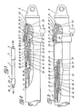
- the cylinder consists of a cylinder 1, in which is slidably mounted with sealing a rod 2, guided at the end 3 of the cylinder 1 crossed by the rod 2 by a ring and at least one dynamic seal (not shown).
- This end piece 5 carries, at one end, a fastener 6, and has at its other end an external thread on a cylindrical part 7 by which the end piece 5 is mounted around the end of the portion 4 of the cylin dre 1, and is retained on the latter thanks to a threaded ring 8, retained on the cylinder 1 by an axial stop 9 disposed in a groove on the outer face of the cylinder 1, a seal being interposed between the part 7 the end piece 5 and the portion 4 of the cylinder 1.
- the rod 2 is provided, at its end external to the cylinder 1, with a fastener 10, and at its internal end to the cylinder 1, having a portion of smaller external diameter 11, of a piston 12, fitted with dynamic seals 13, sliding on the internal wall of the cylinder 1 and guiding the rod 2 in its displacements with respect to the latter.
- the inner ring 21 is separated by a section with predetermined shear breaking load from the outer ring 22 of the internal radial heel, which thus constitutes a frangible element, designated below by the term of mechanical fuse.
- the cage 18 has a cylindrical part of smaller internal diameter 25, radially disposed between the piston 12 and the portion 11 of the rod 2, as well as a cylindrical part of larger internal diameter 26, having radial holes centered in a plane diametral and in each of which is received a ball 19, and surrounding a spring 27 disposed itself around the spacer 20.
- the spring 27 bears by one of its ends against the radial part of the cage 18 separating the two cylindrical parts 25 and 26 of the latter and, by its other end, against a ring 28.
- the ring 28, of cylindrical external shape, slidingly mounted around the spacer 20, is provided with a tail 29 of support against the outer ring 22 of the mechanical fuse, and has on its outer face a groove 30, of partially circular section connected by a conical surface to a cylindrical outer surface 31 of the ring 28, directed towards the face of the latter against laq uelle supports the spring 27.
- the locking of the rod 2 in the retracted position in the cylinder 1 is ensured by the elastic snap-fastening of the heads of the claws 23 behind a step, formed by the end of a sleeve 32, extending in the cylinder 1, radially disposed between an end part of the portion 4 of the latter and the set of claws 23, and held in position by its external radial shoulder 33 clamped between a radial shoulder of the end piece 5 and the end of the portion 4 of the cylinder 1.
- a stop device comprising a locking piston 34, slidably mounted with sealing in a bore of the end piece 5, thanks to the seal 35, and pushed by a spring 36 bearing against the closed bottom of the end piece 5, towards the inside of the cylinder 1, until it is housed inside the heads of the claws 23, to prevent the latter from becoming release from the end of the sleeve 32.
- the stop device is associated linked to a locking control device comprising a cleat 37, pivotally mounted at one end in a central chamber 38 of the end piece 5, and the other end of which is applied against the head of one of the claws 23.
- the pressurization of the chamber 38 of the nozzle 5 through the hydraulic oil supply connection 40 pushes the piston 34 towards the bottom of said nozzle, against the spring 36 and successively unlocks the claws 23, an initial displacement from the rod 2 with the claws 23 released in the cylinder 1, towards the rod out position, and the supply of pressurized oil to the chamber defined by the cylinder 1, the rod 2 and the piston 12, which causes the outlet of the rod, which is locked at the end of its travel, in the extended rod position, by cooperation of the claws 17 with a stop device similar to that just described, but disposed in the end 3 of the cylinder 1, traversed by the rod 2, and therefore in which the locking piston is an annular piston.
- the hydraulic cylinder which has just been described, with mechanical locking and with hydraulic unlocking in the two end-of-travel positions, is intended to be secured by the fastening 6 of its cylinder 1 and the fastening 10 of its rod 2 to two elements, which the actuator must in certain circumstances move relative to one another and, in other circumstances keep rigidly positioned one in relation to the other, when in the retracted rod configuration, at against a charge seeking one of the two elements.
- the jack When the latter is a load causing the tensile stress of the jack, with a value greater than a maximum admissible force, which can be transmitted by the jack from one to the other of the elements, without risk of damaging one of these latter, it is clear that the jack must make it possible to limit the force transmitted to a predetermined acceptable value, and therefore to absorb and dissipate a certain amount of excess energy. This is obtained by calibrating the rupture section at a predetermined shear load, which separates the two inner 21 and outer 22 crowns of the frangible element, at the value of the maximum tensile force that can be transmitted, constituting the trigger value the operation of the device for absorbing energy by plastic deformation, with which the jack is fitted.
- the rupture section breaks and the inner crown 21 separates from the outer crown 22 of the heel of the claws 23, held in place by the device d 'stop.
- the rod 2 begins an exit movement of the cylinder 1, while the spring 27 relaxes maintaining the ring 28 in abutment with its tail 29 against the outer ring 22.
- the part 26 of the cage 18 is therefore displaced axially with respect to the ring 28, and causes the balls 19 to exit from the groove 30, thanks to the conical surface which connects it to the cylindrical external surface 31 of the ring 28, on which the balls 19 come to rest.
- the ball ejection device 19 thus produced makes it possible to project the latter into the recess 41 delimited by the end portion 4 of larger internal diameter of the cylinder 1, after the frangible element has broken.
- the rod 2 then moves in the cylinder 1, driving the balls 19, positioned by the cage 18 so as to bear radially inward on the cylindrical part 31 of the ring 28
- the balls 19 have a larger diameter, of a determined value, the difference between the internal radius of the cylinder 1, in its median part of smaller internal diameter, and the radius of the cylindrical surface 31 of the ring 28 , when they reach the end of the recess 41, they plastically deform the cylinder 1 of the jack, over the remainder of the stroke of the rod 2 in the cylinder 1, as shown in FIG. 3, which causes absorption and an energy dissipation making it possible to limit the force transmitted by the jack to an acceptable value, at least as long as the deformation lasts.
- the amount of energy absorbed is determined in particular by the size of the imprint of the balls 19, by their number and by the thickness of the cylinder 1, as well as by the relative hardnesses of the materials chosen to produce these elements. If the energy absorption must be constant, the deformation will be constant all along the race of the balls 19, using a cylinder of constant section and thickener, but if a variable absorption is desired along the stroke of the balls 19, the cylinder can be of variable thickness adapted to the desired profile.
- the cylinder 1 can be doubled by an internal sleeve, plastically deformable under the same conditions, and molded with a sufficient radial clearance to admit the deformation plastic caused by the balls 19.
- the jack just described has the advantage that the stroke of the balls 19 is practically the same as that of the rod 2 in the cylinder 1, while presenting the advantages of a series mounting of a combined device fulfilling the functions actuator and energy absorption and / or force limitation.
- the length of the jack is therefore not modified by the addition of an additional energy absorption and / or force limitation function to its main function.
- a tared membrane or a pressure relief valve 42 is arranged in the end 3 of the cylinder 1, crossed by the rod 2, so as to allow the purging towards the outside of the jack of the annular chamber. defined between the cylinder 1 and the rod 2, by the piston 12 and the end 3 of the cylinder 1, so that the oil filling this chamber does not prevent the displacement of the piston 12 with the rod 2 in the cylinder 1 , after rupture of the frangible element and during the displacement of the balls 19 plastically deforming the cylinder 1.
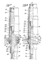
- FIGS. 4 to 6 there is shown a jack provided with an energy absorption and / or force limitation device intended to be stressed in compression, from the extended rod position, by a greater force. to a maximum allowable value.
- the rod 2 is identical, but that all of the parts which it carries on its end portion 11, of smaller external diameter, is arranged in opposite directions, so that the claws 23, provided at their foot with a radial heel constituting the frangible element by its inner 21 and outer 22 crowns, can be locked by a stop device received in the end piece 53 of the end of the cylinder 51 traversed by the rod 2.
- the stop device received in the end piece 53, comprises an annular locking piston 84, slidably mounted with leaktightness inside a bore of the end piece 53 thanks to the gasket 85 and around the rod 2 thanks to the seals 87, and biased by a spring 86 so that the axial extension 89 of the piston 84 comes to lock the claws 23 behind the step of the sleeve 32, the radial heel 33 of which is clamped against the end of the portion 54 of the cylinder 51 by the end piece 53.
- the latter has a central chamber 38, in which the cleat 37 is pivotally mounted, urging the contactor 39 when the claws 23 are locked, as well as a hydraulic oil supply connection 90 for controlling the hydraulic unlocking. and the actuation of the jack.
- this jack is in all respects analogous to that of the jack described with reference to FIGS. 1 to 3, except that the device for absorbing energy and / or limiting the force is triggered by a compression force greater than the predetermined shear breaking load of the section separating the outer 22 and inner 21 crowns of the frangible element, and acting on the locked cylinder in the outgoing rod configuration. Consequently, the tared membrane or the pressure relief valve symbolized at 42 is provided on the end piece 55 of the end of the cylinder 51 not crossed by the rod 2, to allow emptying the cylinder 51 during the re-entry of the rod 2 after rupture of the frangible element.
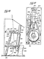
- an oleopneumatic damper comprises a rod 101, slidably mounted with sealing in a substantially vertical cylinder 102, and guided by the rings 103 and 104.
- the ring 103 is arranged in a groove formed on the internal face of a cylindrical sheath 105, retained in a recess provided at the lower end of the cylinder 102 by a nut 106, while the ring 104 is retained against a radial shoulder 107, which is machined in a boss presented by the cylinder 102 on its internal wall, substantially halfway up, by an annular axial stop 108, in which nuts 109 are screwed through radial bores drilled in the cylinder 102.
- the rod 101 contains, at its lower part, a pressurized gas 110, for example a nitrogen chamber, separated by a separating piston 111, slidably mounted with sealing in the rod 101, with a volume of oil filling the rest of the rod 101 as well as the part of the cylinder 102 located above the ring 104, the cylinder 102 being closed by a cover 112 screwed into its upper end.
- a pressurized gas 110 for example a nitrogen chamber
- the rod 101 carries, in its upper end portion, an energy dissipation device by oil rolling 113, represented symbolically, because this device can be constituted by turn known rolling device: permanent orifices, of the type diaphragm, closable by a valve, optionally controlled as a function of the pressure or of the speed of movement of the rod 101 in the cylinder 102, the orifices being of constant or variable cross sections as a function of the speed and / or the direction of movement of the rod in the cylinder, or central orifice formed in a transverse wall of the rod 101 and traversed by a counter rod of variable section carried by the cover 112, so that the passage section varies as a function of the stroke of the rod in the cylinder.
- permanent orifices of the type diaphragm, closable by a valve, optionally controlled as a function of the pressure or of the speed of movement of the rod 101 in the cylinder 102, the orifices being of constant or variable cross sections as a function of
- the pressurized gas chamber 110 tends to push the oil from the rod 101 into the cylinder 102 through the rolling device 113, which ensures the exit of the rod 101 from of the cylinder 102, up to the maximum position rod output shown in FIG. 7, in which the external radial shoulder 114 of the rod 101 abuts against the sheath 105.
- the rod 101 Under load, the rod 101 is pushed towards the inside of the cylinder 102, so that the oil from the cylinder 102 is expelled into the rod 101, through the device 113 ensuring by rolling the dissipation of a certain amount of energy. , and compresses the gas chamber 110, which resiliently absorbs another quantity of energy, which is at least partially restored thereafter to bring the rod 101 into a position of equilibrium under the load in the cylinder 102.
- the cylinder 102 is itself received coaxially in a body 115, of generally cylindrical shape, having an upper portion of smaller internal diameter 116, in which the cylinder 102 is positioned in rotation by means of a groove made in the body 116 and a screw 117 in the cylinder 102.
- a plurality of bolts 118 In the vicinity of the lower end of the body 115, a plurality of bolts 118, the end of the rod of which is threaded, each pass through a radial bore formed in the body 115 as well as a bore in the lower part of larger internal diameter of a plastically deformable sheath 119, doubling the body 115 along the internal wall of the portion of larger internal diameter of the latter, with a sufficient radial clearance to allow the plastic deformation of this sleeve 119 by balls 120, retained by a cage 121 screwed on the external face of the cylinder 102 by bolts 122, and into which the threaded end of the rod bolt 118, l is screwed this is separated from the non-threaded part by a section with predetermined breaking load in shear, or frangible section, so that the rod of the bolts 118 constitutes a mechanical fuse for the axial displacements of the cylinder 102 in the body 115.
- the non-part threaded from the bolt rod 118 also passes through a centering ring 123, disposed between the sheath 119 and the cage 121.
- the balls 120 are radially inwardly supported in a groove around the cylinder 102, and their diameter is greater than the difference between the radius of the part with the smallest internal diameter of the sleeve 119 and the radius at the bottom of the groove of the cylinder 102.
- a compass one branch of which (not shown) is connected to the lower part of the rod 101, has its other branch 124 articulated on a yoke 125 which is retained around the lower part of the body 115, between a shoulder 126 of the latter and a nut 127, and integral in rotation with the body 115 by means of a bolt 128, the rod of which has a non-threaded part , passing through a radial bore of the yoke 125, separated from a threaded end part and screwed into the body 115 by a section with predetermined shear breaking load, or frangible section, so that the bolt rod 128 constitutes a mechanical fuse for the rotations of the rod 101 in the body 115.
- this transmitted force reaches the trigger value of the energy absorption and / or force limitation device, with which the shock absorber is fitted, that is to say the predetermined value of the breaking shear load rods of the bolts 118, the latter break and the cylinder 102 slides in the body 115 by driving the balls 120 via the cage 121.
- the balls 120 plastically deform the sheath 119 along its generatrices, which causes absorption and energy dissipation, which can be adjusted to a chosen value, under the same conditions as above, by varying the number of balls, their diameter, their hardness and that of the sheath, as well as the thickness and profile of this last.
- the force transmitted from the rod 101 to the body 115 can thus be limited to an acceptable value.
- the damper has the advantage that the stroke of the energy absorption device is only slightly less than the length of the body 115, and that the latter is not modified by the addition of the function additional energy absorption and / or effort limitation.
- the body 115 may have, on its internal wall, longitudinal grooves 129 in which the plastic deformation of the sheath 119 will take place, moreover in bearing radially outward on the bosses of the body 115 separating the grooves 129 from each other.
- the strut shown in FIG. 10 consists of a body 151, of cylindrical shape, one end of which is closed by an end piece 152, screwed into the body 151, and provided with a mechanical connection device such as a ball joint 153, and the other end of which is traversed by a rod 154.
- This rod 154 whose end external to the cylinder 151 also carries a nozzle 155, provided with a ball joint 156, and screwed into the rod 154 in an adjustable manner to adjust the length of the strut to a desired dimension, thanks to its threaded part 157, present inside the cylinder 151, a cylindrical portion of smaller internal diameter 158, externally threaded, extending by a portion of conical end 159.
- balls 160 On the latter bear balls 160, retained in a tubular cage 161, screwed onto the thread of the cylindrical portion 158 of the rod 154, and sliding inside a plastically deformable sheath 162, substantially crimped in the middle self ur of the part of the balls 160 which protrudes from the cage 161, and doubling the body 151 inside the latter with a sufficient radial clearance to allow its plastic deformation, with absorption and dissipation of energy, when the balls 160 are moved with the rod 154 by means of the cage 161, in one or other direction in the body 151.
- the cage 161 has respectively a cylindrical end portion 163 or 164, sliding inside the sheath 162 before its deformation.
- the sleeve 162 is held in axial position in the cylinder 151 by bolts 165, with a partially threaded rod, screwed into a bore of the cylinder 151 at its end near the end piece 152, and by bolts 166, with a partially threaded rod screwed in a radial bore of the cylinder 151 at its end traversed by the rod 154, the non-threaded parts of the rods of the bolts 165 and 166 passing through bores made in the opposite ends of the sleeve 162.
- the non-threaded part of the rod of the bolts 166 also has a frangible section with a predetermined shear breaking load, so that it constitutes a mechanical fuse.
- the end of these rods penetrate into a radial bore of the rod 154, so that the bolts 166 ensure the axial locking in the initial position of the rod 154 in the cylinder 151.
- the counter-plug therefore consists of a rod 154 blocked in the half-out position in the cylinder 151 by mechanical fuses, the rupture of which takes place at a predetermined value of the compressive or tensile stress exerted on the against sheet, and corresponding to the trigger value of the energy absorption device and / or force limitation by plastic deformation of the sleeve 162 by the balls 160.
- the rod 154 can be locked in the initial position, respectively with the rod extended or the rod retracted by the bolts 166, so that substantially the entire length of cylinder 151 can be used as the stroke of the energy absorbing device.
- the sleeve 162 is then crimped onto the balls 160 by its corresponding end.
- sheath 162 which has the advantage of being able to be replaced after deformation, and to produce the counter-plug so that the balls 160 plastically deform the cylinder 151.
- the jack, the shock absorber and the strut which have just been described with reference to FIGS. 1 to 10 are well suited to the equipment of landing gear of aerodynes, and in particular of helicopters, to which these components make it possible to give an “anti-crash” ability.
- the legs of the undercarriages In normal use, and before landing, the legs of the undercarriages must be held rigidly in position relative to a cell to which they are linked directly or indirectly, and it is only after takeoff that the undercarriages can be, optionally, raised either in the wing, or in the fuselage of the aerodyne, or even in stubs of wings or fins or fuselage boxes, provided laterally at the bottom of the latter.
- the rigid positioning of the undercarriage legs, which carry the contact member with the ground, such as a wheel, a skate or a ski, by means of a suspension device, for example an oleopneumatic damper housed in the shaft of the undercarriage and absorbing impact energy, is generally provided by means of mechanical or hydraulic struts, of constant or telescopic length, and of hydraulic, mechanical or even electrical jacks, capable of act as bracing devices, such as a strut, and / or operating devices.
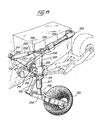
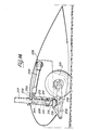
- the left undercarriage, shown in FIGS. 11 to 14, of a main landing gear for a helicopter, the right undercarriage of which is symmetrical with respect to the longitudinal plane of symmetry of the helicopter, is of the so-called “pendulum” type. And with rearward longitudinal lift in a wing stump or fin or in a fuselage box.
- This undercarriage comprises a substantially vertical leg in the extended gear position, the barrel of which consists of the body 201 of a shock absorber such as that described previously with reference to FIGS. 7 to 9, and which has, at its upper end, a longitudinal attachment 202 on which the free end of the rod 203 of a jack is pivotally mounted, arranged in a substantially longitudinal direction, and such as that described above with reference to FIGS.
- the body 201 also has at its upper end a transverse attachment 206 directed towards the cell of the helicopter, and on which is articulated the end of the rod 207 of a strut such as that previously described with reference to the figure 10, arranged in a transverse plane, and the cylinder 208 of which is articulated at 209 on the structure of the fin, in the vicinity of a lifting axis 212 described below.
- the body 201 also has, substantially at half its height, a transverse fastener 210, directed towards the helicopter's cell, by which the body 201 is pivotally mounted around a journal 211 longitudinal and substantially horizontal, carried by the transverse axis 212 pivotally mounted in the bearings 213 and 214 of the fin structure.
- a transverse fastener 210 directed towards the helicopter's cell, by which the body 201 is pivotally mounted around a journal 211 longitudinal and substantially horizontal, carried by the transverse axis 212 pivotally mounted in the bearings 213 and 214 of the fin structure.
- the other end of the compass branch 216 is pivoted on the front part of a pendulum 220, on the central part of which s articulates the lower end of the rod 218, and the rear part of which is made into a yoke in which a wheel fitted with a tire 221 is rotatably mounted.
- the force transmitted by the cylinder 217 to the body 201 is greater than operating forces of the undercarriage under normal conditions, is greater than the predetermined breaking load of the frangible elements of the energy absorption device by plastic deformation with which the shock absorber is equipped, so that the operation of this device is triggers, and that the force transmitted to the cell does not cause damage to the latter, since a large part of the impact energy is absorbed and dissipated by the operation of the energy absorption device, all along the vertical stroke of the cylinder 217 in the body 201.
- the undercarriage After the vertical impact, the undercarriage is in the position shown in FIG. 14.
- the cylinder 217 protrudes from the upper part of the body 201, and the balance 220 is in abutment against the lower part of the latter or against the yoke 215, the tire fitted to the wheel 221 having possibly burst, after having elastically absorbed a certain amount of energy at impact by compression of its air chamber, and after having dissipated a certain other amount of energy at impact by the deformation of the tire.
- the shape and the inclination of the pendulum 220 cause forces from the obstacle against which the wheel 221 abuts introduced on the shock absorber rod 218, which can, under the same conditions as for a vertical shock at too high a speed, become blocked in the cylinder 217, even in the event of the tire bursting, and cause tripping at desired force of the energy absorption device by plastic deformation, housed between the cylinder 217 and the body 201.
- the energy absorption devices by plastic deformation equipping the shock absorber and the jack can be triggered according to the importance of the vertical and longitudinal components of the forces coming from the ground compared to the trigger thresholds for these devices.
- the balance 220 and the rod 218 are subjected to a torsional moment around the axis of the shock absorber, and this torsional moment is transmitted by the compass branch 216 to the yoke 215. If the force which requests the yoke 215 in rotation around the body 201 is greater than the predetermined value of the breaking shear load of the frangible element 219, the latter breaks and disengages in rotation the yoke 215 from the body 201.
- the yoke 215 is then pivoted with the compass branch 216 around the body 201, and consequently allows the orientation of the assembly constituted by the wheel 221, the balance 220 and the rod 218 in the direction of the force coming from the ground.
- the rupture threshold of the frangible element 219 is lower than the rupture threshold of the frangible elements of the energy absorption by plastic deformation equipping on the one hand the shock absorber, on the other hand the jack.
- the wheel 221, the pendulum 220 and the rod 218 can be oriented in the direction of the force by breaking the frangible element 219, as previously explained.
- this force causes rotation of the undercarriage leg around the pin 211 either inwardly relative to the helicopter, or outwardly, in the direction of the lateral force, by urging the strut either in traction or in compression.
- the strut will limit the force transmitted to the structure of the helicopter by absorbing energy by virtue of its elongation or shortening, accompanying the rotation of the body 201 around the pin 211.
- this undercarriage therefore makes it possible to limit, to a predetermined value, the force produced by an impact or an impact against an obstacle in the connecting elements that are the strut and the jack, ensuring in normal use rigid positioning undercarriage legs in a position of use, due to their deformation in traction and / or compression.
- the main advantage of this undercarriage is that it decouples the normal landing function from the high speed impact protection function, in all possible directions, this protection function being provided by different components, depending on the direction of the force d 'impact. In fact the vertical components are absorbed by the shock absorber and possibly its energy absorption device by plastic deformation, while the longitudinal components are absorbed by the jack and the transverse components are absorbed by the strut.
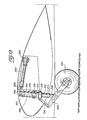
- the lateral undercarriage shown in FIGS. 15 to 18, of a main helicopter landing gear with lateral lift in the fuselage comprises a leg consisting of a box 251 and a barrel 252 mounted pivoting one on the other around a longitudinal axis 253.
- the box 251 has a generally triangular shape and has two legs 254 by each of which the box 251 is pivotally mounted around a portion of longitudinal axis 255, integral with the structure of the helicopter , as well as a yoke 256 receiving the fastener 257 provided at the upper end of the barrel 252 for the pivoting of the latter on the box 251 around the axis 253.
- the box 251 On its lower face, in the gear-out position, the box 251 also has a fastener 258, on which is articulated the end of the rod 259 of a jack such as that described above with reference to FIGS. 1 to 3, the cylinder 260 of which is articulated on a fastener 261 provided in the part bottom of the fuselage housing, in which the lander is housed in the retracted gear position, while the portions of longitudinal axes 255 are fixed substantially at mid-height in this housing.
- the barrel 252 of the leg consists of the body of a damper such as that previously described with reference to Figures 7 to 9, and there is a yoke 262, mounted on the lower end of the barrel 252, a cylinder 263 shock absorber protruding from this lower end and in which is received the shock absorber rod 264, the lower end 256 of which carries a rocket facing outwards and on which is mounted a wheel 266 equipped with a tire.
- the alignment of the wheel 266 relative to the undercarriage leg is ensured by a compass, the upper branch 267 and the lower branch 268 of which are pivotally mounted one on the other and respectively on the yoke 262 and on the part lower 265 and the rod 264, around longitudinal axes.
- the barrel 252 also has an anterior attachment 269 and a posterior attachment 270 on which the ends of rods 271 and 273 of struts respectively are hinged, such as that previously described with reference to FIG. 10, and whose cylinders 272 and 274 are respectively articulated on fasteners 275 and 276 secured to the structure of the helicopter, at a height intermediate between that of fastener 261 of the jack and that of the portions of longitudinal axes 255 in the extension l 'from one another, and respectively located in front and behind the transverse plane passing through the barrel 252.
- the box 251 and the leg barrel 252 are practically arranged one against the other, the longitudinal pivot axis 253 being positioned in the upper part of the housing, above the axis of linkage formed by the two portions of longitudinal axes 255, and the undercarriage is locked in this position retracted train by the jack itself locked in the rod out position.
- the descent of the undercarriage is ensured by controlling the re-entry of the rod 259 into the cylinder 260 of the jack, which causes the rotation of the casing 251 down around the lifting axis, and the descent of the barrel 252, maintained substantially in the same direction during its downward movement, thanks to the substantially deformable parallelogram mounting formed by the two counter-plugs, the box 251 and the barrel 252 with the vertical wall of the housing.
- the undercarriage is locked in the extended gear position by locking the cylinder in the retracted rod position, as shown in FIG. 6.
- the landing gear is lifted by controlling the opposite operations of output of rod 259 from cylinder 260 of the jack and of rotation in opposite direction, upwards, of box 251.
- the rod 264 of the shock absorber practically locks in the cylinder 263, and the absorption device of energy by plastic deformation housed between the cylinder 263 and the barrel 252 is triggered at the desired level of effort.
- the two struts 271-272 and 273-274 can operate simultaneously, in traction or in compression, depending on the direction of impact, in order to absorb a certain amount of energy and limit the lateral force transmitted to the cell.
- the two struts therefore tend to oppose any transverse rotation of the barrel 252 of the undercarriage around the longitudinal pivot axis 253 of the latter on the box 251, as long as the axial components urging these struts are not greater than the release velocity of the device for absorbing energy by plastic deformation which equips them.
- the landing gear which has just been described provides the same advantages as that described with reference to FIGS. 11 to 14, insofar as it also ensures the decoupling of the normal landing function from the impact protection function at high speed in all possible directions, this latter function being, in this case also, provided by different components according to the direction of the impact force.
- the invention is not limited to the two exemplary embodiments of landing gear which have just been described, but on the contrary extends to all trains fitted with at least one component, of the strut type, jack or damper, according to the invention.
- the train with rearward longitudinal lift can be fitted out in a wing train as in a fuselage train, and that it can be of the pendulum type, as described, or still of the direct sliding type, as is the case of the train described with reference to FIGS. 15 to 18, where the wheel is directly carried by the lower part of the damper rod, slidably mounted axially in the cylinder and in the barrel of the undercarriage leg.
- the lateral bracing of these trains can be provided by an internal lateral strut and / or an external lateral strut relative to the longitudinal plane passing through the undercarriage leg, these struts articulated on the leg either at above, or below the lifting axis.
- the longitudinal bracing can be ensured not only by a longitudinal jack placed behind the undercarriage leg, and locked in the retracted rod position, so as to be stressed in traction by the forces resulting from a forward impact, but also or alternatively by a longitudinal cylinder disposed at the front of the undercarriage, locked in the extended rod position , and stressed in compression by the force resulting from a forward impact.
- the longitudinal bracing can be ensured by a longitudinal cylinder placed at the rear of the leg, and locked in position rod extended, so as to be stressed in compression by a force resulting from an impact towards the front, and / or by a longitudinal jack arranged at the front of the leg and locked in position rod retracted, to be stressed in traction by the same type of effort.
- the longitudinal bracing is provided either by a front longitudinal strut and / or by a rear longitudinal strut, articulated one and / or the other on the leg above or below. below the lifting axis. If the cylinder attachment on the leg is located below the longitudinal lifting axis, the lateral bracing can be ensured by a cylinder locked in the extended rod position.
- the invention also relates to fixed landing gears, obtained by using only as hydraulic struts the jacks fitted to the landing gears mentioned above.
Landscapes
- Engineering & Computer Science (AREA)
- Mechanical Engineering (AREA)
- General Engineering & Computer Science (AREA)
- Aviation & Aerospace Engineering (AREA)
- Vibration Dampers (AREA)
- General Details Of Gearings (AREA)
- Gears, Cams (AREA)
- Gear Transmission (AREA)
Applications Claiming Priority (2)
| Application Number | Priority Date | Filing Date | Title |
|---|---|---|---|
| FR8115432A FR2511103A1 (fr) | 1981-08-10 | 1981-08-10 | Composants munis d'un dispositif d'absorption d'energie par deformation plastique et/ou de limitation d'effort, et trains d'atterrissage d'aerodynes equipes de tels composants |
| FR8115432 | 1981-08-10 |
Publications (2)
| Publication Number | Publication Date |
|---|---|
| EP0072323A1 EP0072323A1 (fr) | 1983-02-16 |
| EP0072323B1 true EP0072323B1 (fr) | 1985-11-06 |
Family
ID=9261318
Family Applications (1)
| Application Number | Title | Priority Date | Filing Date |
|---|---|---|---|
| EP82401479A Expired EP0072323B1 (fr) | 1981-08-10 | 1982-08-05 | Composants munis d'un dispositif d'absorption d'énergie par déformation plastique et/ou de limitation d'effort, et trains d'atterrissage d'aérodynes équipés de tels composants |
Country Status (6)
| Country | Link |
|---|---|
| US (1) | US4537374A (cg-RX-API-DMAC7.html) |
| EP (1) | EP0072323B1 (cg-RX-API-DMAC7.html) |
| JP (1) | JPS5836797A (cg-RX-API-DMAC7.html) |
| CA (1) | CA1206945A (cg-RX-API-DMAC7.html) |
| DE (1) | DE3267292D1 (cg-RX-API-DMAC7.html) |
| FR (1) | FR2511103A1 (cg-RX-API-DMAC7.html) |
Cited By (1)
| Publication number | Priority date | Publication date | Assignee | Title |
|---|---|---|---|---|
| WO2025257237A1 (de) * | 2024-06-13 | 2025-12-18 | Guru Technologies Gmbh | Radaufhängung für ein fahrzeug |
Families Citing this family (48)
| Publication number | Priority date | Publication date | Assignee | Title |
|---|---|---|---|---|
| FR2537542B1 (fr) * | 1982-12-08 | 1985-11-15 | Aerospatiale | Trains d'atterissage a patins equipes de composants munis d'un dispositif d'absorption d'energie par deformation plastique et/ou de limitation d'effort, et composants de ce type |
| GB2134462B (en) * | 1983-01-28 | 1986-07-23 | Automotive Products Plc | An aircraft undercarriage |
| JPS6122040A (ja) * | 1984-07-10 | 1986-01-30 | Mitsubishi Rayon Co Ltd | メタクロレイン及びメタクリル酸の製造法 |
| FR2608242B1 (fr) * | 1986-12-12 | 1989-03-31 | Aerospatiale | Amortisseur-verin, contre-fiche le comportant, et train d'atterrissage equipe d'une telle contre-fiche |
| DE4028448A1 (de) * | 1990-09-07 | 1992-03-12 | Suspa Compart Ag | Reversibler pralldaempfer, insbesondere fuer kraftfahrzeuge |
| US5924714A (en) * | 1991-06-11 | 1999-07-20 | Cannondale Corporation | Bicycle suspension system |
| US5494302A (en) * | 1991-06-11 | 1996-02-27 | Cannondale Corporation | Suspension assembly for a vehicle |
| US5320374A (en) * | 1991-06-11 | 1994-06-14 | Cannondale Corporation | Suspension fork |
| DE4121497A1 (de) * | 1991-06-28 | 1993-02-04 | Audi Ag | Stossfaengersystem fuer kraftfahrzeuge |
| FR2681308B1 (fr) * | 1991-09-17 | 1993-12-17 | Messier Bugatti | Amortisseur anti-crash relevable. |
| FR2687123B1 (fr) * | 1992-02-11 | 1994-04-08 | Eram | Train d'atterrissage relevable d'aeronef, notamment pour helicoptere. |
| FR2689087B1 (fr) * | 1992-03-31 | 1994-05-13 | Messier Bugatti | Atterrisseur relevable d'aerodynes, notamment pour helicopteres. |
| GB2269986B (en) * | 1992-07-30 | 1997-03-19 | Flight Equip & Eng | Vehicle seats |
| FR2719880B1 (fr) * | 1994-05-11 | 1996-06-07 | Messier Bugatti | Dispositif de sécurité à élément télescopique limiteur d'accélération, destiné à assurer la protection d'un système transporté à bord d'un véhicule en cas de choc. |
| US6212974B1 (en) * | 1998-12-17 | 2001-04-10 | United Technologies Corporation | Variable stiffness positioning link for a gearbox |
| FR2805799B1 (fr) * | 2000-03-02 | 2002-06-14 | Messier Dowty Sa | Atterisseur d'aeronef a axe de pivotement de jambe fortement deporte |
| US6471198B2 (en) | 2000-06-02 | 2002-10-29 | Lord Corporation | Vibration isolator |
| AU2001280681A1 (en) | 2000-07-21 | 2002-02-05 | Hamilton Sunstrand | Vibration isolation device with load dependent stiffness |
| US6533459B2 (en) | 2001-01-31 | 2003-03-18 | The Torrington Company | Adjustable, self-aligning, linear roller bearing |
| FR2840041B1 (fr) * | 2002-05-23 | 2004-07-16 | Snecma Moteurs | Biellette fusible avec amortisseur et butee antiretour |
| RU2245823C2 (ru) * | 2003-04-07 | 2005-02-10 | Нижегородское открытое акционерное общество "Гидромаш" | Убирающаяся опора шасси летательного аппарата |
| US7578465B2 (en) | 2004-01-20 | 2009-08-25 | Lord Corporation | Aircraft front nose landing gear and method of making an aircraft landing gear |
| US7571876B2 (en) * | 2004-01-20 | 2009-08-11 | Lord Corporation | Aircraft landing gear assembly shimmy damper |
| US7874572B2 (en) * | 2005-01-10 | 2011-01-25 | Energy Absorption Systems, Inc. | Towable impact attenuator |
| FR2884802B1 (fr) * | 2005-04-22 | 2008-11-14 | Eurocopter France | Structure porteuse et aeronef a voilure tournante |
| FR2884801B1 (fr) * | 2005-04-22 | 2008-11-14 | Eurocopter France | Atterrisseur auxillaire de nez, structure porteuse et aeronef a voilure tournante |
| FR2885596B1 (fr) * | 2005-05-12 | 2007-07-06 | Eurocopter France | Procede et systeme anti-crash, atterrisseur et aeronef |
| WO2008095048A1 (en) | 2007-01-30 | 2008-08-07 | Traffix Devices, Inc. | Trailer mounted crash attenuator |
| US7441817B1 (en) * | 2007-04-23 | 2008-10-28 | Tma Acquisition, Llc | Trailer mounted crash attenuation system |
| GB2452938B (en) * | 2007-09-19 | 2011-08-10 | Messier Dowty Ltd | Load indicator |
| US8973725B2 (en) * | 2008-07-21 | 2015-03-10 | Goodrich Corporation | Shock strut with pressure relief |
| AT509399B1 (de) * | 2010-01-22 | 2015-09-15 | Wunderwerk Film Gmbh | Trainingsanordnung zum training von flugzuständen eines senkrechtstart- und/oder senkrechtlandefähigen luftfahrzeuges |
| FR2959207B1 (fr) * | 2010-04-26 | 2012-04-20 | Eurocopter France | Systeme a absortion d'energie pour un atterisseur, et aeronef muni dudit systeme a absorption d'energie |
| FR2965544B1 (fr) * | 2010-10-04 | 2012-10-19 | Eurocopter France | Train d'atterrissage, aeronef muni dudit train d'atterrissage, et procede d'atterrissage dudit aeronef |
| US9205917B2 (en) * | 2010-11-05 | 2015-12-08 | Goodrich Corporation | Vertically retracting side articulating landing gear for aircraft |
| FR2983831B1 (fr) * | 2011-12-12 | 2014-01-10 | Eurocopter France | Procede et aeronef a voilure tournante optimise afin de minimiser les consequences d'un atterrissage glisse d'urgence hors norme |
| US9051046B2 (en) | 2012-09-18 | 2015-06-09 | Bell Helicopter Textron Inc. | Vertical support system |
| US9303715B2 (en) | 2013-03-10 | 2016-04-05 | Oshkosh Defense, Llc | Limiting system for a vehicle suspension component |
| US10611203B1 (en) | 2017-04-27 | 2020-04-07 | Oshkosh Defense, Llc | Suspension element lockout |
| US12491943B1 (en) | 2013-03-10 | 2025-12-09 | Oshkosh Defense, Llc | Systems and methods for a military vehicle |
| US11130563B2 (en) * | 2018-11-07 | 2021-09-28 | The Boeing Company | Monolithic outboard gear beam support fitting |
| US11498666B2 (en) * | 2020-12-16 | 2022-11-15 | Goodrich Corporation | Shock strut assemblies for landing gear |
| CN117203127A (zh) * | 2021-04-22 | 2023-12-08 | Tusas-土耳其航空航天工业公司 | 起落架 |
| CN114030596B (zh) * | 2021-12-17 | 2023-08-11 | 江西洪都航空工业集团有限责任公司 | 一种带卡环内锁的套筒式撑杆 |
| US11939045B2 (en) | 2022-04-27 | 2024-03-26 | The Boeing Company | Landing gear assembly for an aircraft, a landing gear system, and a method |
| GB2619015A (en) * | 2022-05-20 | 2023-11-29 | Airbus Operations Ltd | Aircraft landing gear assembly |
| EP4428031A1 (en) * | 2023-03-06 | 2024-09-11 | Lilium GmbH | Landing gear for a vertical take-off and landing aircraft |
| US12304669B2 (en) * | 2023-07-31 | 2025-05-20 | Drone Amplified, Inc. | Drone landing gear |
Citations (1)
| Publication number | Priority date | Publication date | Assignee | Title |
|---|---|---|---|---|
| DE2313821A1 (de) * | 1973-03-20 | 1974-10-10 | Liebherr Aera Technik Gmbh | Arbeitszylinder-innenverriegelung |
Family Cites Families (18)
| Publication number | Priority date | Publication date | Assignee | Title |
|---|---|---|---|---|
| CA556947A (en) * | 1958-05-06 | Dowty Equipment Limited | Telescopic struts | |
| GB458005A (en) * | 1935-03-28 | 1936-12-10 | Elektronmetall Gmbh | Improvements in and relating to adjustable struts for air-craft |
| US2369007A (en) * | 1943-06-10 | 1945-02-06 | Gabriel Co | Shock absorber |
| US2752112A (en) * | 1953-03-31 | 1956-06-26 | North American Aviation Inc | Steerable and retractable aircraft landing gear |
| US3356318A (en) * | 1965-08-03 | 1967-12-05 | Livshits Yakov Abramovich | Aircraft landing gear |
| US3392599A (en) * | 1966-12-30 | 1968-07-16 | Gen Motors Corp | Energy absorbing device |
| GB1209566A (en) * | 1966-12-30 | 1970-10-21 | Gen Motors Corp | Energy absorbers |
| FR1543222A (fr) * | 1967-06-12 | 1968-10-25 | Peugeot | Dispositif destiné à absorber de l'énergie et ses applications, en particulier aux colonnes de direction des véhicules automobiles |
| FR2085498A1 (cg-RX-API-DMAC7.html) * | 1970-04-27 | 1971-12-24 | Saab Ab | |
| US3696891A (en) * | 1970-10-29 | 1972-10-10 | Hartwell Corp The | Energy absorbing device |
| US3664463A (en) * | 1970-11-10 | 1972-05-23 | Martin Marietta Corp | Deployable shock absorber |
| US3862668A (en) * | 1973-06-13 | 1975-01-28 | Eaton Corp | Hydrostatic transmission control system |
| US3820634A (en) * | 1973-08-10 | 1974-06-28 | Hartwell Corp | Shock resisting energy absorbing device |
| US3904153A (en) * | 1974-02-25 | 1975-09-09 | Boeing Co | Steerable and retractable aircraft nose landing gear assembly |
| US3997133A (en) * | 1975-07-30 | 1976-12-14 | Textron, Inc. | Crash attenuation landing gear |
| US4150805A (en) * | 1976-10-20 | 1979-04-24 | Ara, Inc. | Crash survivable seat |
| FR2413585A1 (fr) * | 1977-12-27 | 1979-07-27 | Alkan R & Cie | Dispositif absorbeur d'energie cinetique |
| DE2918179A1 (de) * | 1979-05-05 | 1980-11-06 | Messerschmitt Boelkow Blohm | Daempfungsanordnung |
-
1981
- 1981-08-10 FR FR8115432A patent/FR2511103A1/fr active Granted
-
1982
- 1982-08-05 US US06/405,647 patent/US4537374A/en not_active Expired - Lifetime
- 1982-08-05 DE DE8282401479T patent/DE3267292D1/de not_active Expired
- 1982-08-05 EP EP82401479A patent/EP0072323B1/fr not_active Expired
- 1982-08-10 JP JP57139079A patent/JPS5836797A/ja active Granted
- 1982-08-10 CA CA000409071A patent/CA1206945A/fr not_active Expired
Patent Citations (1)
| Publication number | Priority date | Publication date | Assignee | Title |
|---|---|---|---|---|
| DE2313821A1 (de) * | 1973-03-20 | 1974-10-10 | Liebherr Aera Technik Gmbh | Arbeitszylinder-innenverriegelung |
Cited By (1)
| Publication number | Priority date | Publication date | Assignee | Title |
|---|---|---|---|---|
| WO2025257237A1 (de) * | 2024-06-13 | 2025-12-18 | Guru Technologies Gmbh | Radaufhängung für ein fahrzeug |
Also Published As
| Publication number | Publication date |
|---|---|
| JPH0260560B2 (cg-RX-API-DMAC7.html) | 1990-12-17 |
| EP0072323A1 (fr) | 1983-02-16 |
| FR2511103A1 (fr) | 1983-02-11 |
| US4537374A (en) | 1985-08-27 |
| JPS5836797A (ja) | 1983-03-03 |
| DE3267292D1 (en) | 1985-12-12 |
| CA1206945A (fr) | 1986-07-02 |
| FR2511103B1 (cg-RX-API-DMAC7.html) | 1983-12-30 |
Similar Documents
| Publication | Publication Date | Title |
|---|---|---|
| EP0072323B1 (fr) | Composants munis d'un dispositif d'absorption d'énergie par déformation plastique et/ou de limitation d'effort, et trains d'atterrissage d'aérodynes équipés de tels composants | |
| EP0113616B1 (fr) | Trains d'atterrissage à patins équipés de composants munis d'un dispositif d'absorption d'énergie par déformation plastique et/ou de limitation d'effort | |
| EP0275735B1 (fr) | Amortisseur-vérin, contre-fiche le comportant, et train d'atterrissage équipé d'une telle contre-fiche | |
| FR2689087A1 (fr) | Atterrisseur relevable d'aérodynes, notamment pour hélicoptères. | |
| CA1177500A (fr) | Amortisseur-verin | |
| EP1291545B1 (fr) | Barre de liaison à absorption d'énergie, et giravion équipé de telles barres de liaison comme barres de suspension d'une boíte de transmission | |
| FR2935680A1 (fr) | Train d'atterrissage arriere a hauteur variable | |
| EP0398797A1 (fr) | Dispositif de réduction de la souplesse d'un amortisseur oléopneumatique d'atterrisseur, et amortisseur et atterrisseur le comportant | |
| EP2048078A1 (fr) | Vérin de rétraction, atterrisseur de giravion muni d'un tel vérin de rétraction | |
| EP1721827B1 (fr) | Procédé et système anti-crash, atterrisseur et aéronef | |
| EP2380809B1 (fr) | Système à absorption d'énergie pour un atterrisseur, et aéronef muni dudit système à absorption d'énergie | |
| EP2436598B1 (fr) | Train d'atterissage, aéronef muni dudit train d'atterissage, et procédé d'atterissage dudit aéronef | |
| FR3056552A1 (fr) | Harpon d'ancrage externe pour aeronef | |
| FR3018501A1 (fr) | Dispositif et procede pour le controle actif du train d’atterrissage d’un aeronef | |
| EP0288377B1 (fr) | Système de roulement pour aéronef | |
| EP2360093B1 (fr) | Aeronef a voilure tournante muni d'un atterrisseur d'urgence | |
| FR2687123A1 (fr) | Train d'atterrissage relevable d'aeronef, notamment pour helicoptere. | |
| FR3001708A1 (fr) | Train d'atterrissage retractable, aeronef muni dudit train d'atterrissage, et procede de manoeuvre dudit train d'atterrissage | |
| FR2795042A1 (fr) | Avion comportant un train d'atterrissage a detachement controle en cas d'accident | |
| FR3062184A1 (fr) | Systeme de protection contre les atterrissages violents pour aeronef | |
| EP1106501B1 (fr) | Train d'atterrissage auxiliaire avant pour aéronef | |
| EP4347392B1 (fr) | Atterrisseur d'aéronef doté d'au moins une roue motorisée | |
| EP4476135B1 (fr) | Jambe pour atterrisseur d'aeronef equipe d'un accumulateur, atterrisseur comprenant une telle jambe et aeronef comprenant au moins un tel atterrisseur | |
| FR2510511A1 (fr) | Train d'atterrissage |
Legal Events
| Date | Code | Title | Description |
|---|---|---|---|
| PUAI | Public reference made under article 153(3) epc to a published international application that has entered the european phase |
Free format text: ORIGINAL CODE: 0009012 |
|
| AK | Designated contracting states |
Designated state(s): DE GB IT |
|
| 17P | Request for examination filed |
Effective date: 19830330 |
|
| ITF | It: translation for a ep patent filed | ||
| RAP1 | Party data changed (applicant data changed or rights of an application transferred) |
Owner name: AEROSPATIALE SOCIETE NATIONALE INDUSTRIELLE |
|
| GRAA | (expected) grant |
Free format text: ORIGINAL CODE: 0009210 |
|
| AK | Designated contracting states |
Designated state(s): DE GB IT |
|
| REF | Corresponds to: |
Ref document number: 3267292 Country of ref document: DE Date of ref document: 19851212 |
|
| PLBE | No opposition filed within time limit |
Free format text: ORIGINAL CODE: 0009261 |
|
| STAA | Information on the status of an ep patent application or granted ep patent |
Free format text: STATUS: NO OPPOSITION FILED WITHIN TIME LIMIT |
|
| 26N | No opposition filed | ||
| ITTA | It: last paid annual fee | ||
| PGFP | Annual fee paid to national office [announced via postgrant information from national office to epo] |
Ref country code: GB Payment date: 19950801 Year of fee payment: 14 |
|
| PGFP | Annual fee paid to national office [announced via postgrant information from national office to epo] |
Ref country code: DE Payment date: 19950807 Year of fee payment: 14 |
|
| PG25 | Lapsed in a contracting state [announced via postgrant information from national office to epo] |
Ref country code: GB Effective date: 19960805 |
|
| GBPC | Gb: european patent ceased through non-payment of renewal fee |
Effective date: 19960805 |
|
| PG25 | Lapsed in a contracting state [announced via postgrant information from national office to epo] |
Ref country code: DE Effective date: 19970501 |