EP0072323B1 - Components provided with a device for energy absorpton via plastic deformation and/or for stress limitation, and aircraft landing gears equipped with these components - Google Patents
Components provided with a device for energy absorpton via plastic deformation and/or for stress limitation, and aircraft landing gears equipped with these components Download PDFInfo
- Publication number
- EP0072323B1 EP0072323B1 EP82401479A EP82401479A EP0072323B1 EP 0072323 B1 EP0072323 B1 EP 0072323B1 EP 82401479 A EP82401479 A EP 82401479A EP 82401479 A EP82401479 A EP 82401479A EP 0072323 B1 EP0072323 B1 EP 0072323B1
- Authority
- EP
- European Patent Office
- Prior art keywords
- rod
- cylinder
- jack
- bracing
- shaft
- Prior art date
- Legal status (The legal status is an assumption and is not a legal conclusion. Google has not performed a legal analysis and makes no representation as to the accuracy of the status listed.)
- Expired
Links
Images


Classifications
-
- B—PERFORMING OPERATIONS; TRANSPORTING
- B64—AIRCRAFT; AVIATION; COSMONAUTICS
- B64C—AEROPLANES; HELICOPTERS
- B64C25/00—Alighting gear
- B64C25/32—Alighting gear characterised by elements which contact the ground or similar surface
- B64C25/58—Arrangements or adaptations of shock-absorbers or springs
- B64C25/60—Oleo legs
-
- F—MECHANICAL ENGINEERING; LIGHTING; HEATING; WEAPONS; BLASTING
- F16—ENGINEERING ELEMENTS AND UNITS; GENERAL MEASURES FOR PRODUCING AND MAINTAINING EFFECTIVE FUNCTIONING OF MACHINES OR INSTALLATIONS; THERMAL INSULATION IN GENERAL
- F16F—SPRINGS; SHOCK-ABSORBERS; MEANS FOR DAMPING VIBRATION
- F16F7/00—Vibration-dampers; Shock-absorbers
- F16F7/12—Vibration-dampers; Shock-absorbers using plastic deformation of members
- F16F7/125—Units with a telescopic-like action as one member moves into, or out of a second member
Definitions
- the present invention relates to components provided with a device for absorbing energy by plastic deformation and / or limiting force, as well as landing gear of aerodynes equipped with such components.
- the invention relates to hydraulic and / or mechanical components, such as actuator, shock absorber and strut, intended for the equipment of helicopter landing gear, in order to give latter cases a capacity commonly referred to as "anti-crash".
- the rolling elements are maintained in predetermined positions in perforations formed in a sleeve, mounted coaxially between the telescopic members, of generally cylindrical shape, and suitable for moving with these rolling elements and for maintain a predetermined spacing between them during their rolling resulting from a relative displacement of the telescopic members, so that this sleeve acts as a cage for the rolling elements.
- the mounting of the rolling elements clamped between the telescopic members is chosen to compressively compress these rolling elements between portions, most often cylindrical, of the telescopic members, so that these rolling elements exert, in the contact zone with telescopic members, an average contact pressure of value greater than the deformation contact pressure for the material constituting at least the deformable telescopic member, that is to say at the pressure for which establishes a distribution of the stresses leading to plastic deformation in the contact zone, this plastic deformation producing a high and localized energy dissipation.
- the value of the energy dissipation per unit of displacement of the telescopic members depends on the degree or the depth of the plastic deformation, which itself depends on the load of the rolling elements, i.e. their number , of the degree of tightening, defined from the value whose radial dimension or diameter of the rolling elements is greater than the difference between the radial dimensions or external and internal radii of the telescopic members in the contact zone before deformation.
- This velocity of energy dissipation also depends on the relative hardness of the materials constituting the rolling elements and the telescopic members.
- the use of such devices provides energy absorption characteristics which can be predicted with great precision.
- one or both of the telescopic members is produced with an internal or external dimension which varies continuously, so as to obtain a convergent or divergent part for example so that the rolling elements meet resistance. respectively increasing or decreasing during a telescopic movement of the members.
- the wall thickness of one of the two members can vary along the latter to present a variable resistance to plastic deformation.
- a steering shaft comprising two parts mounted telescopically one inside the other and integral in rotation by pins simultaneously ensuring the axial positioning of these two parts in a relative position of normal operation, is rotatably mounted in a support envelope consisting of a lower tubular portion, integral with the chassis of the vehicle, and mounted telescopically in a portion upper tubular, connected to the dashboard by a unidirectional breaking fitting by means of pins.
- a support envelope consisting of a lower tubular portion, integral with the chassis of the vehicle, and mounted telescopically in a portion upper tubular, connected to the dashboard by a unidirectional breaking fitting by means of pins.
- energy absorption devices are also known, the structure of which has many analogies with those of the devices previously considered, since they include printing means, also presenting in the form of balls, rollers, etc., but also in the form of a ring, means intended to effect a relative displacement of said printing means and of an energy absorbing member, appearing under the shape of a sleeve.
- the means intended to effect a relative displacement comprises a support member, facing the energy absorption member, and carrying, by example in a radial chamber having at least one conical wall facing the latter, the printing means, so that the latter accompany the movement of the support member relative to the energy absorption member, and are repelled in this last.
- the energy absorption member is a deformable member which is elastically qualified as an elastomer member in this patent FR-A-2 110 078 , and arranged so as to undergo localized elastic deformation by compression as well as elastic compression and elongation distributed laterally with respect to the localized elastic deformation zone.
- the energy absorption member constituted by a sleeve having elastomeric qualities, and produced in particular from natural rubbers or silicone, allows the production of a device providing the advantages of a hydraulic or pneumatic damper, since the shocks and jolts can be absorbed, while presenting only a structure of cost price and reduced weight.
- aircraft landing gear is equipped with various components, such as jacks, shock absorbers and struts, which fulfill a main hydraulic and / or mechanical function, and which each comprise a tubular element inside which is received a telescopic element, immobilized with respect to the tubular element in at least one position of normal use of the component, by at least one locking device.
- components such as jacks, shock absorbers and struts, which fulfill a main hydraulic and / or mechanical function, and which each comprise a tubular element inside which is received a telescopic element, immobilized with respect to the tubular element in at least one position of normal use of the component, by at least one locking device.
- the internal locking mechanism comprises elastic claws carried by the piston or cylinder of the jack, a locking step carried respectively by the cylinder or the piston of the jack, and a locking piston, sliding respectively in the cylinder or around the rod. , and resiliently returned to the claw locking position when they are blocked behind the step.
- This locking mechanism is hydraulically released, because the locking piston is pushed back against the return spring by the actuating pressure of the jack, because the spring chamber is in communication with the jack chamber in which reigns the lowest pressure.
- the problem underlying the invention consists in taking advantage of any possibility of relative travel between the rod and the cylinder of such a jack, in order to ensure absorption and dissipation of energy which allows the jack to not transmit to the structure of the aerodyne that an admissible fraction of the too high load which requests it, under abnormal conditions of use.
- the present invention aims to adapt energy absorption mechanisms by plastic deformation, of the type described in FR-A-1 549 884 and its addition FR-A-2 010 302, in filling components.
- a main hydraulic and / or mechanical function such as an actuating and / or bracing cylinder, of the type described in DE-A-2 313 821, or an oleopneumatic damper, which already constitutes by itself a device for absorption and dissipation of energy, or a bracing strut of a main element, so that these components can fulfill an additional function of energy absorption and / or limitation of effort, for a purpose security and protection of a structure with which they are associated, and comprising parts to which violent forces, resulting from shocks and jolts applied to the structure, must not be transmitted without damping, attenuation or limitation.
- the invention also aims to design landing gear for aerodynes, in particular helicopter landing machines, equipped with components according to the invention, and having an “anti-crash” capacity.
- a component according to the invention fulfilling a main hydraulic and / or mechanical function, of the jack, damper or strut type, and comprising a tubular element inside which is received a telescopic element immobilized vis-à-vis screw of the tubular element in at least one position of use by at least one locking device, is characterized in that it also comprises a device for absorbing energy by plastic deformation and / or limiting force, comprising a set of rolling elements held by a cage and interposed with clamping between an internal member and an external member mounted one inside the other, and of which at least the external member is a member with deformation load predetermined plastic, said members being capable of sliding into one another after rupture of a frangible element with predetermined breaking load and included in the locking device, so that the rolling elements pro evoke, in a manner so known, energy dissipation by plastic deformation of at least the external member, which is integral with the tubular element, the telescopic element constituting the internal member which drives the cage for retaining the
- a component of the cylinder type according to the invention makes it possible, from the extended and locked rod position, to take advantage of all the possible stroke of the rod in the cylinder for make the rolling elements and the internal and external members of the energy absorption device cooperate by plastic deformation, and therefore to dissipate a significant amount of energy, as soon as the operation of the energy absorption device is triggered by the rupture of the frangible element that comprises the locking device of the jack.
- the breaking threshold of the frangible element corresponds to the maximum load that the cylinder can transmit to the structure of the aerodyne without damaging it, this maximum load being, of course, greater than the loads undergone by the cylinder under normal conditions of use, and which can be transmitted to the structure.
- the breaking threshold thus chosen for the frangible element makes it possible to avoid any blockage of the rod in the cylinder and to control an energy absorption as soon as this is necessary so that the structure is not overloaded.
- the plastically deformable external member is constituted either by the tubular element itself, or by a sheath, doubling the tubular element inside the latter, over at least part of its length, with sufficient radial clearance to admit the plastic deformation caused by the rolling elements, and removable to allow the component to be repaired by replacing the sheath and at least the frangible element.
- the tubular element can be constituted by the body, of generally cylindrical shape, of a strut also comprising a rod, constituting the telescopic element, slidably mounted in the body and immobilized vis-à-vis of the latter in an initial position in which a part of the rod penetrates into the body, by means of at least one bolt with partially threaded rod, screwed into a radial thread passing through the body at its end through which the rod passes, and such that the end of the bolt rod penetrates into a radial bore in the strut rod and simultaneously constitutes the locking device and the frangible element at a predetermined breaking load, the cage for retaining the rolling elements being secured to the outside of the part of the rod internal to the body and the rolling elements being in radial support inwards against the rod and outwards in an imprint of the plastically deformable member, const ituted either by the body or by the sheath retained by the partially threaded rod of the bolt (s) against the internal wall of the
- the device for absorbing energy by plastic deformation of the strut can be used in cases of stress greater than the breaking threshold of the frangible element respectively in tension only, in tension or in compression, and in compression only.
- the tubular element can also be constituted by the cylinder of a hydraulic cylinder, comprising a rod constituting the telescopic element, slidably mounted in the cylinder and guided in the latter by a piston carried at its internal end to the cylinder, the rod of the cylinder being immobilized in the cylinder in at least one position of normal use of the cylinder by a locking device with elastic claws whose heads are locked against a step on the internal wall of the cylinder by at least one piston of locking, and the feet of which are integral with a radial heel, constituting the frangible element with a predetermined breaking load, and having an outer ring separated by a breaking section from an inner ring driven by the cylinder rod at the same while the bearing element cage is carried around the end of the internal cylinder cylinder rod.
- the rolling elements are retained radially inwards by a ring mounted to slide between the cage retaining the rolling elements and the jack rod, and having on its outer face a groove used for housing the rolling elements, in the position of use of the jack, and connected by an inclined ramp to a cylindrical portion, the ring being urged elastically towards the outer crown of the frangible element - to cause, at the following the rupture of the latter, the exit of the rolling elements from the groove and their displacement on the inclined ramp then on the cylindrical portion of the ring, during a relative displacement of the cage driving the rolling elements and driven by the rod vis-à-vis the ring, held in abutment against the outer crown of the frangible element before being driven with the rod by the inner crown of the frangible element, so that the rolling elements are moved radially outwards, projecting relative to the cage, and are capable of causing plastic deformations of the member under load of predetermined plastic deformation.
- a recess is provided at the end of the cylinder surrounding the cage, the rolling elements and the ring, in position d normal use of the jack, and extends axially over a distance allowing the coming of the rolling elements projecting relative to the cage, following the rupture of the frangible element and an initial displacement of the rod in the cylinder of the jack.
- the energy absorption device by plastic deformation and / or limitation of effort of the jack is stressed respectively in tension or in compression by an effort which can be less than, equal to or greater than the breaking point of the frangible element.
- the tubular element of the component can also be constituted by the body, having at least a part of generally cylindrical shape, of a damper also comprising a cylinder, constituting the telescopic element, at least partially housed in the generally cylindrical part of the body, and immobilized in the position of use in this body by at least one bolt with partially threaded rod passing through a radial bore formed in the body screwed into a radial heel of the cylinder, so as to simultaneously constitute the device locking device and the frangible element, a damper rod being slidably mounted with sealing in the damper cylinder, which also contains an elastic energy absorption device, capable of returning the rod to the initial position in the cylinder, as well as a device for dissipating energy by rolling a volume of hydraulic oil displaced in the shock absorber everywhere relative displacement f of the rod and cylinder.
- the external radial heel into which the threaded end of the rod or bolts is screwed, simultaneously constitutes the cage of the rolling elements, retained on the external wall of the damper cylinder.
- the rolling elements are radially inwardly supported in a groove formed on the external wall of the cylinder, and the cage, in a fixed position relative to this groove, causes the rolling elements to cooperate with the member.
- plastically deformable also in this case, either by the body of the damper itself, or by a sleeve retained by at least the bolt (s) against the internal wall of the body.
- a triggering threshold of the energy absorption device by plastic deformation of the damper is chosen which is greater than. forces undergone by the shock absorber under normal operating conditions but less than a force which would damage the structure supported by the shock absorber in the event of the rod blocking in the latter's cylinder.
- the components according to the invention have the advantage that the useful stroke of their devices for absorbing energy by plastic deformation and / or limiting force is the same as that of their rod when these components fulfill their main function, while having the advantages of a series connection.
- the length of a component according to the invention is therefore not modified by the addition of the additional function of energy absorption and / or limitation of effort compared to analogous components of the prior art.
- the main landing gear for aerodynes in particular for helicopters, according to the invention, comprising, for each undercarriage, a leg whose shaft is equipped with a shock absorber provided with a rod whose lower end, in position d landing, is connected to at least one member of contact with the ground, such as a wheel, the leg being maintained in the use position, substantially vertical, for landing and take-off, by a lateral bracing device and a longitudinal bracing device, each articulated on the one hand, on the leg and on the other hand, on the aerodyne structure, are characterized in that their damper is a damper according to the invention, the body of which directly constitutes the shaft of the landing gear leg, and the frangible element of which at a predetermined breaking load ruptures for any force transmitted by the shock absorber cylinder to the barrel of the leg, which is above a threshold indicating a blockage of the rod d 'damper in the cylinder, due to abnormal landing conditions, so that the operation of the energy absorption device
- the lateral bracing device and / or the longitudinal bracing device of the landing gear according to the invention comprise at least one strut and / or a jack according to the invention, including the absorption devices energy by respective plastic deformation is triggered when the component of the force, respectively supported by the strut and / or the jack in the lateral or longitudinal direction of the bracing that this strut or this jack provides, is greater than the threshold of rupture of the frangible element, this threshold corresponding to a maximum admissible value of this compost of the force under normal landing conditions.
- the bracing cylinder which comprises one of the bracing devices simultaneously constitutes a maneuvering cylinder, controlling the rotation of the undercarriage leg about a lifting axis, between a "retracted gear” position and a " undercarriage ”, as well as possibly locking the leg in these two positions, so that the landing gears according to the invention are of the so-called lifting type.
- the liftable landing gears can be of the so-called “pendulum” type, the damper rod of which is articulated, at its lower end, on a pendulum carrying at its rear end the contact member with the ground, such as a wheel, and the front end of which is pivotally mounted on a branch of compass connecting the pendulum to a yoke which surrounds the shank of the leg and on which the branch of compass is itself pivotally mounted.
- the tilting liftable trains according to the invention are characterized in that the yoke and the barrel are secured in rotation by at least one second frangible element, at a predetermined breaking load less than the breaking load of the frangible element of the device.
- the barrel of the leg of each undercarriage is secured to a transverse lifting axis, pivotally mounted on the structure of the aerodyne, and, according to the invention, the maneuvering of each undercarriage and its longitudinal bracing are ensured by a jack arranged in a substantially longitudinal direction, the shank of the leg being pivotally mounted on the lifting axis around a longitudinal pin, and the lateral bracing being provided by a counter-plug, arranged in a transverse plane, so that apart from the train maneuvers, the undercarriage legs can pivot, from the extended gear position, respectively around the transverse lifting axis and the longitudinal journal, after the respective actuations of the absorption devices energy by plastic deformation of the jack and the counter-plug.
- the liftable landing gears according to the invention can also be of the so-called transverse lift type, the shaft of the leg of each undercarriage is integral with a longitudinal lift axis pivotally mounted on the structure of the aerodyne.
- trains are characterized in that the operation of each undercarriage and its lateral bracing are ensured by a jack arranged in a substantially transverse plane, and in that the shank of the leg is pivotally mounted on the axis lifting around a transverse swivel, and that the longitudinal bracing is provided by a strut arranged in a substantially longitudinal direction, so that outside the train maneuvers, the landing gear legs can pivot, from the position with the gear extended, respectively around the longitudinal lifting axis and the transverse journal after the respective trips of the energy absorption devices by plastic deformation of the jack and the counter-plug.
- the invention also relates to liftable landing gear, of the type which is raised laterally in the fuselage, and comprising for each undercarriage a jack controlling the operation of the leg around a longitudinal lifting axis integral with the structure of aerodyne.
- Such trains according to the invention are characterized in that the undercarriage leg consists of a box, of generally triangular shape, pivoting around the lifting axis, and on which is on the one hand pivotally mounted the upper end of the barrel of the leg and on the other hand articulated one end of the jack, so that the devices for absorbing energy by plastic deformation of the shock absorber and of the jack can be successively used for the absorption of a significant vertical component of a force requesting the contact member with the ground, and in that the lateral bracing and the longitudinal bracing are provided by a strut inclined towards the front and a strut inclined towards the rear of aerodyne with respect to the barrel of the leg.
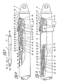
- the cylinder consists of a cylinder 1, in which is slidably mounted with sealing a rod 2, guided at the end 3 of the cylinder 1 crossed by the rod 2 by a ring and at least one dynamic seal (not shown).
- This end piece 5 carries, at one end, a fastener 6, and has at its other end an external thread on a cylindrical part 7 by which the end piece 5 is mounted around the end of the portion 4 of the cylin dre 1, and is retained on the latter thanks to a threaded ring 8, retained on the cylinder 1 by an axial stop 9 disposed in a groove on the outer face of the cylinder 1, a seal being interposed between the part 7 the end piece 5 and the portion 4 of the cylinder 1.
- the rod 2 is provided, at its end external to the cylinder 1, with a fastener 10, and at its internal end to the cylinder 1, having a portion of smaller external diameter 11, of a piston 12, fitted with dynamic seals 13, sliding on the internal wall of the cylinder 1 and guiding the rod 2 in its displacements with respect to the latter.
- the inner ring 21 is separated by a section with predetermined shear breaking load from the outer ring 22 of the internal radial heel, which thus constitutes a frangible element, designated below by the term of mechanical fuse.
- the cage 18 has a cylindrical part of smaller internal diameter 25, radially disposed between the piston 12 and the portion 11 of the rod 2, as well as a cylindrical part of larger internal diameter 26, having radial holes centered in a plane diametral and in each of which is received a ball 19, and surrounding a spring 27 disposed itself around the spacer 20.
- the spring 27 bears by one of its ends against the radial part of the cage 18 separating the two cylindrical parts 25 and 26 of the latter and, by its other end, against a ring 28.
- the ring 28, of cylindrical external shape, slidingly mounted around the spacer 20, is provided with a tail 29 of support against the outer ring 22 of the mechanical fuse, and has on its outer face a groove 30, of partially circular section connected by a conical surface to a cylindrical outer surface 31 of the ring 28, directed towards the face of the latter against laq uelle supports the spring 27.
- the locking of the rod 2 in the retracted position in the cylinder 1 is ensured by the elastic snap-fastening of the heads of the claws 23 behind a step, formed by the end of a sleeve 32, extending in the cylinder 1, radially disposed between an end part of the portion 4 of the latter and the set of claws 23, and held in position by its external radial shoulder 33 clamped between a radial shoulder of the end piece 5 and the end of the portion 4 of the cylinder 1.
- a stop device comprising a locking piston 34, slidably mounted with sealing in a bore of the end piece 5, thanks to the seal 35, and pushed by a spring 36 bearing against the closed bottom of the end piece 5, towards the inside of the cylinder 1, until it is housed inside the heads of the claws 23, to prevent the latter from becoming release from the end of the sleeve 32.
- the stop device is associated linked to a locking control device comprising a cleat 37, pivotally mounted at one end in a central chamber 38 of the end piece 5, and the other end of which is applied against the head of one of the claws 23.
- the pressurization of the chamber 38 of the nozzle 5 through the hydraulic oil supply connection 40 pushes the piston 34 towards the bottom of said nozzle, against the spring 36 and successively unlocks the claws 23, an initial displacement from the rod 2 with the claws 23 released in the cylinder 1, towards the rod out position, and the supply of pressurized oil to the chamber defined by the cylinder 1, the rod 2 and the piston 12, which causes the outlet of the rod, which is locked at the end of its travel, in the extended rod position, by cooperation of the claws 17 with a stop device similar to that just described, but disposed in the end 3 of the cylinder 1, traversed by the rod 2, and therefore in which the locking piston is an annular piston.
- the hydraulic cylinder which has just been described, with mechanical locking and with hydraulic unlocking in the two end-of-travel positions, is intended to be secured by the fastening 6 of its cylinder 1 and the fastening 10 of its rod 2 to two elements, which the actuator must in certain circumstances move relative to one another and, in other circumstances keep rigidly positioned one in relation to the other, when in the retracted rod configuration, at against a charge seeking one of the two elements.
- the jack When the latter is a load causing the tensile stress of the jack, with a value greater than a maximum admissible force, which can be transmitted by the jack from one to the other of the elements, without risk of damaging one of these latter, it is clear that the jack must make it possible to limit the force transmitted to a predetermined acceptable value, and therefore to absorb and dissipate a certain amount of excess energy. This is obtained by calibrating the rupture section at a predetermined shear load, which separates the two inner 21 and outer 22 crowns of the frangible element, at the value of the maximum tensile force that can be transmitted, constituting the trigger value the operation of the device for absorbing energy by plastic deformation, with which the jack is fitted.
- the rupture section breaks and the inner crown 21 separates from the outer crown 22 of the heel of the claws 23, held in place by the device d 'stop.
- the rod 2 begins an exit movement of the cylinder 1, while the spring 27 relaxes maintaining the ring 28 in abutment with its tail 29 against the outer ring 22.
- the part 26 of the cage 18 is therefore displaced axially with respect to the ring 28, and causes the balls 19 to exit from the groove 30, thanks to the conical surface which connects it to the cylindrical external surface 31 of the ring 28, on which the balls 19 come to rest.
- the ball ejection device 19 thus produced makes it possible to project the latter into the recess 41 delimited by the end portion 4 of larger internal diameter of the cylinder 1, after the frangible element has broken.
- the rod 2 then moves in the cylinder 1, driving the balls 19, positioned by the cage 18 so as to bear radially inward on the cylindrical part 31 of the ring 28
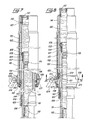
- the balls 19 have a larger diameter, of a determined value, the difference between the internal radius of the cylinder 1, in its median part of smaller internal diameter, and the radius of the cylindrical surface 31 of the ring 28 , when they reach the end of the recess 41, they plastically deform the cylinder 1 of the jack, over the remainder of the stroke of the rod 2 in the cylinder 1, as shown in FIG. 3, which causes absorption and an energy dissipation making it possible to limit the force transmitted by the jack to an acceptable value, at least as long as the deformation lasts.
- the amount of energy absorbed is determined in particular by the size of the imprint of the balls 19, by their number and by the thickness of the cylinder 1, as well as by the relative hardnesses of the materials chosen to produce these elements. If the energy absorption must be constant, the deformation will be constant all along the race of the balls 19, using a cylinder of constant section and thickener, but if a variable absorption is desired along the stroke of the balls 19, the cylinder can be of variable thickness adapted to the desired profile.
- the cylinder 1 can be doubled by an internal sleeve, plastically deformable under the same conditions, and molded with a sufficient radial clearance to admit the deformation plastic caused by the balls 19.
- the jack just described has the advantage that the stroke of the balls 19 is practically the same as that of the rod 2 in the cylinder 1, while presenting the advantages of a series mounting of a combined device fulfilling the functions actuator and energy absorption and / or force limitation.
- the length of the jack is therefore not modified by the addition of an additional energy absorption and / or force limitation function to its main function.
- a tared membrane or a pressure relief valve 42 is arranged in the end 3 of the cylinder 1, crossed by the rod 2, so as to allow the purging towards the outside of the jack of the annular chamber. defined between the cylinder 1 and the rod 2, by the piston 12 and the end 3 of the cylinder 1, so that the oil filling this chamber does not prevent the displacement of the piston 12 with the rod 2 in the cylinder 1 , after rupture of the frangible element and during the displacement of the balls 19 plastically deforming the cylinder 1.
- FIGS. 4 to 6 there is shown a jack provided with an energy absorption and / or force limitation device intended to be stressed in compression, from the extended rod position, by a greater force. to a maximum allowable value.
- the rod 2 is identical, but that all of the parts which it carries on its end portion 11, of smaller external diameter, is arranged in opposite directions, so that the claws 23, provided at their foot with a radial heel constituting the frangible element by its inner 21 and outer 22 crowns, can be locked by a stop device received in the end piece 53 of the end of the cylinder 51 traversed by the rod 2.
- the stop device received in the end piece 53, comprises an annular locking piston 84, slidably mounted with leaktightness inside a bore of the end piece 53 thanks to the gasket 85 and around the rod 2 thanks to the seals 87, and biased by a spring 86 so that the axial extension 89 of the piston 84 comes to lock the claws 23 behind the step of the sleeve 32, the radial heel 33 of which is clamped against the end of the portion 54 of the cylinder 51 by the end piece 53.
- the latter has a central chamber 38, in which the cleat 37 is pivotally mounted, urging the contactor 39 when the claws 23 are locked, as well as a hydraulic oil supply connection 90 for controlling the hydraulic unlocking. and the actuation of the jack.
- this jack is in all respects analogous to that of the jack described with reference to FIGS. 1 to 3, except that the device for absorbing energy and / or limiting the force is triggered by a compression force greater than the predetermined shear breaking load of the section separating the outer 22 and inner 21 crowns of the frangible element, and acting on the locked cylinder in the outgoing rod configuration. Consequently, the tared membrane or the pressure relief valve symbolized at 42 is provided on the end piece 55 of the end of the cylinder 51 not crossed by the rod 2, to allow emptying the cylinder 51 during the re-entry of the rod 2 after rupture of the frangible element.
- an oleopneumatic damper comprises a rod 101, slidably mounted with sealing in a substantially vertical cylinder 102, and guided by the rings 103 and 104.
- the ring 103 is arranged in a groove formed on the internal face of a cylindrical sheath 105, retained in a recess provided at the lower end of the cylinder 102 by a nut 106, while the ring 104 is retained against a radial shoulder 107, which is machined in a boss presented by the cylinder 102 on its internal wall, substantially halfway up, by an annular axial stop 108, in which nuts 109 are screwed through radial bores drilled in the cylinder 102.
- the rod 101 contains, at its lower part, a pressurized gas 110, for example a nitrogen chamber, separated by a separating piston 111, slidably mounted with sealing in the rod 101, with a volume of oil filling the rest of the rod 101 as well as the part of the cylinder 102 located above the ring 104, the cylinder 102 being closed by a cover 112 screwed into its upper end.
- a pressurized gas 110 for example a nitrogen chamber
- the rod 101 carries, in its upper end portion, an energy dissipation device by oil rolling 113, represented symbolically, because this device can be constituted by turn known rolling device: permanent orifices, of the type diaphragm, closable by a valve, optionally controlled as a function of the pressure or of the speed of movement of the rod 101 in the cylinder 102, the orifices being of constant or variable cross sections as a function of the speed and / or the direction of movement of the rod in the cylinder, or central orifice formed in a transverse wall of the rod 101 and traversed by a counter rod of variable section carried by the cover 112, so that the passage section varies as a function of the stroke of the rod in the cylinder.
- permanent orifices of the type diaphragm, closable by a valve, optionally controlled as a function of the pressure or of the speed of movement of the rod 101 in the cylinder 102, the orifices being of constant or variable cross sections as a function of
- the pressurized gas chamber 110 tends to push the oil from the rod 101 into the cylinder 102 through the rolling device 113, which ensures the exit of the rod 101 from of the cylinder 102, up to the maximum position rod output shown in FIG. 7, in which the external radial shoulder 114 of the rod 101 abuts against the sheath 105.
- the rod 101 Under load, the rod 101 is pushed towards the inside of the cylinder 102, so that the oil from the cylinder 102 is expelled into the rod 101, through the device 113 ensuring by rolling the dissipation of a certain amount of energy. , and compresses the gas chamber 110, which resiliently absorbs another quantity of energy, which is at least partially restored thereafter to bring the rod 101 into a position of equilibrium under the load in the cylinder 102.
- the cylinder 102 is itself received coaxially in a body 115, of generally cylindrical shape, having an upper portion of smaller internal diameter 116, in which the cylinder 102 is positioned in rotation by means of a groove made in the body 116 and a screw 117 in the cylinder 102.
- a plurality of bolts 118 In the vicinity of the lower end of the body 115, a plurality of bolts 118, the end of the rod of which is threaded, each pass through a radial bore formed in the body 115 as well as a bore in the lower part of larger internal diameter of a plastically deformable sheath 119, doubling the body 115 along the internal wall of the portion of larger internal diameter of the latter, with a sufficient radial clearance to allow the plastic deformation of this sleeve 119 by balls 120, retained by a cage 121 screwed on the external face of the cylinder 102 by bolts 122, and into which the threaded end of the rod bolt 118, l is screwed this is separated from the non-threaded part by a section with predetermined breaking load in shear, or frangible section, so that the rod of the bolts 118 constitutes a mechanical fuse for the axial displacements of the cylinder 102 in the body 115.
- the non-part threaded from the bolt rod 118 also passes through a centering ring 123, disposed between the sheath 119 and the cage 121.
- the balls 120 are radially inwardly supported in a groove around the cylinder 102, and their diameter is greater than the difference between the radius of the part with the smallest internal diameter of the sleeve 119 and the radius at the bottom of the groove of the cylinder 102.
- a compass one branch of which (not shown) is connected to the lower part of the rod 101, has its other branch 124 articulated on a yoke 125 which is retained around the lower part of the body 115, between a shoulder 126 of the latter and a nut 127, and integral in rotation with the body 115 by means of a bolt 128, the rod of which has a non-threaded part , passing through a radial bore of the yoke 125, separated from a threaded end part and screwed into the body 115 by a section with predetermined shear breaking load, or frangible section, so that the bolt rod 128 constitutes a mechanical fuse for the rotations of the rod 101 in the body 115.
- this transmitted force reaches the trigger value of the energy absorption and / or force limitation device, with which the shock absorber is fitted, that is to say the predetermined value of the breaking shear load rods of the bolts 118, the latter break and the cylinder 102 slides in the body 115 by driving the balls 120 via the cage 121.
- the balls 120 plastically deform the sheath 119 along its generatrices, which causes absorption and energy dissipation, which can be adjusted to a chosen value, under the same conditions as above, by varying the number of balls, their diameter, their hardness and that of the sheath, as well as the thickness and profile of this last.
- the force transmitted from the rod 101 to the body 115 can thus be limited to an acceptable value.
- the damper has the advantage that the stroke of the energy absorption device is only slightly less than the length of the body 115, and that the latter is not modified by the addition of the function additional energy absorption and / or effort limitation.
- the body 115 may have, on its internal wall, longitudinal grooves 129 in which the plastic deformation of the sheath 119 will take place, moreover in bearing radially outward on the bosses of the body 115 separating the grooves 129 from each other.
- the strut shown in FIG. 10 consists of a body 151, of cylindrical shape, one end of which is closed by an end piece 152, screwed into the body 151, and provided with a mechanical connection device such as a ball joint 153, and the other end of which is traversed by a rod 154.
- This rod 154 whose end external to the cylinder 151 also carries a nozzle 155, provided with a ball joint 156, and screwed into the rod 154 in an adjustable manner to adjust the length of the strut to a desired dimension, thanks to its threaded part 157, present inside the cylinder 151, a cylindrical portion of smaller internal diameter 158, externally threaded, extending by a portion of conical end 159.
- balls 160 On the latter bear balls 160, retained in a tubular cage 161, screwed onto the thread of the cylindrical portion 158 of the rod 154, and sliding inside a plastically deformable sheath 162, substantially crimped in the middle self ur of the part of the balls 160 which protrudes from the cage 161, and doubling the body 151 inside the latter with a sufficient radial clearance to allow its plastic deformation, with absorption and dissipation of energy, when the balls 160 are moved with the rod 154 by means of the cage 161, in one or other direction in the body 151.
- the cage 161 has respectively a cylindrical end portion 163 or 164, sliding inside the sheath 162 before its deformation.
- the sleeve 162 is held in axial position in the cylinder 151 by bolts 165, with a partially threaded rod, screwed into a bore of the cylinder 151 at its end near the end piece 152, and by bolts 166, with a partially threaded rod screwed in a radial bore of the cylinder 151 at its end traversed by the rod 154, the non-threaded parts of the rods of the bolts 165 and 166 passing through bores made in the opposite ends of the sleeve 162.
- the non-threaded part of the rod of the bolts 166 also has a frangible section with a predetermined shear breaking load, so that it constitutes a mechanical fuse.
- the end of these rods penetrate into a radial bore of the rod 154, so that the bolts 166 ensure the axial locking in the initial position of the rod 154 in the cylinder 151.
- the counter-plug therefore consists of a rod 154 blocked in the half-out position in the cylinder 151 by mechanical fuses, the rupture of which takes place at a predetermined value of the compressive or tensile stress exerted on the against sheet, and corresponding to the trigger value of the energy absorption device and / or force limitation by plastic deformation of the sleeve 162 by the balls 160.
- the rod 154 can be locked in the initial position, respectively with the rod extended or the rod retracted by the bolts 166, so that substantially the entire length of cylinder 151 can be used as the stroke of the energy absorbing device.
- the sleeve 162 is then crimped onto the balls 160 by its corresponding end.
- sheath 162 which has the advantage of being able to be replaced after deformation, and to produce the counter-plug so that the balls 160 plastically deform the cylinder 151.
- the jack, the shock absorber and the strut which have just been described with reference to FIGS. 1 to 10 are well suited to the equipment of landing gear of aerodynes, and in particular of helicopters, to which these components make it possible to give an “anti-crash” ability.
- the legs of the undercarriages In normal use, and before landing, the legs of the undercarriages must be held rigidly in position relative to a cell to which they are linked directly or indirectly, and it is only after takeoff that the undercarriages can be, optionally, raised either in the wing, or in the fuselage of the aerodyne, or even in stubs of wings or fins or fuselage boxes, provided laterally at the bottom of the latter.
- the rigid positioning of the undercarriage legs, which carry the contact member with the ground, such as a wheel, a skate or a ski, by means of a suspension device, for example an oleopneumatic damper housed in the shaft of the undercarriage and absorbing impact energy, is generally provided by means of mechanical or hydraulic struts, of constant or telescopic length, and of hydraulic, mechanical or even electrical jacks, capable of act as bracing devices, such as a strut, and / or operating devices.
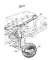
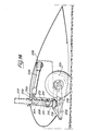
- the left undercarriage, shown in FIGS. 11 to 14, of a main landing gear for a helicopter, the right undercarriage of which is symmetrical with respect to the longitudinal plane of symmetry of the helicopter, is of the so-called “pendulum” type. And with rearward longitudinal lift in a wing stump or fin or in a fuselage box.
- This undercarriage comprises a substantially vertical leg in the extended gear position, the barrel of which consists of the body 201 of a shock absorber such as that described previously with reference to FIGS. 7 to 9, and which has, at its upper end, a longitudinal attachment 202 on which the free end of the rod 203 of a jack is pivotally mounted, arranged in a substantially longitudinal direction, and such as that described above with reference to FIGS.
- the body 201 also has at its upper end a transverse attachment 206 directed towards the cell of the helicopter, and on which is articulated the end of the rod 207 of a strut such as that previously described with reference to the figure 10, arranged in a transverse plane, and the cylinder 208 of which is articulated at 209 on the structure of the fin, in the vicinity of a lifting axis 212 described below.
- the body 201 also has, substantially at half its height, a transverse fastener 210, directed towards the helicopter's cell, by which the body 201 is pivotally mounted around a journal 211 longitudinal and substantially horizontal, carried by the transverse axis 212 pivotally mounted in the bearings 213 and 214 of the fin structure.
- a transverse fastener 210 directed towards the helicopter's cell, by which the body 201 is pivotally mounted around a journal 211 longitudinal and substantially horizontal, carried by the transverse axis 212 pivotally mounted in the bearings 213 and 214 of the fin structure.
- the other end of the compass branch 216 is pivoted on the front part of a pendulum 220, on the central part of which s articulates the lower end of the rod 218, and the rear part of which is made into a yoke in which a wheel fitted with a tire 221 is rotatably mounted.
- the force transmitted by the cylinder 217 to the body 201 is greater than operating forces of the undercarriage under normal conditions, is greater than the predetermined breaking load of the frangible elements of the energy absorption device by plastic deformation with which the shock absorber is equipped, so that the operation of this device is triggers, and that the force transmitted to the cell does not cause damage to the latter, since a large part of the impact energy is absorbed and dissipated by the operation of the energy absorption device, all along the vertical stroke of the cylinder 217 in the body 201.
- the undercarriage After the vertical impact, the undercarriage is in the position shown in FIG. 14.
- the cylinder 217 protrudes from the upper part of the body 201, and the balance 220 is in abutment against the lower part of the latter or against the yoke 215, the tire fitted to the wheel 221 having possibly burst, after having elastically absorbed a certain amount of energy at impact by compression of its air chamber, and after having dissipated a certain other amount of energy at impact by the deformation of the tire.
- the shape and the inclination of the pendulum 220 cause forces from the obstacle against which the wheel 221 abuts introduced on the shock absorber rod 218, which can, under the same conditions as for a vertical shock at too high a speed, become blocked in the cylinder 217, even in the event of the tire bursting, and cause tripping at desired force of the energy absorption device by plastic deformation, housed between the cylinder 217 and the body 201.
- the energy absorption devices by plastic deformation equipping the shock absorber and the jack can be triggered according to the importance of the vertical and longitudinal components of the forces coming from the ground compared to the trigger thresholds for these devices.
- the balance 220 and the rod 218 are subjected to a torsional moment around the axis of the shock absorber, and this torsional moment is transmitted by the compass branch 216 to the yoke 215. If the force which requests the yoke 215 in rotation around the body 201 is greater than the predetermined value of the breaking shear load of the frangible element 219, the latter breaks and disengages in rotation the yoke 215 from the body 201.
- the yoke 215 is then pivoted with the compass branch 216 around the body 201, and consequently allows the orientation of the assembly constituted by the wheel 221, the balance 220 and the rod 218 in the direction of the force coming from the ground.
- the rupture threshold of the frangible element 219 is lower than the rupture threshold of the frangible elements of the energy absorption by plastic deformation equipping on the one hand the shock absorber, on the other hand the jack.
- the wheel 221, the pendulum 220 and the rod 218 can be oriented in the direction of the force by breaking the frangible element 219, as previously explained.
- this force causes rotation of the undercarriage leg around the pin 211 either inwardly relative to the helicopter, or outwardly, in the direction of the lateral force, by urging the strut either in traction or in compression.
- the strut will limit the force transmitted to the structure of the helicopter by absorbing energy by virtue of its elongation or shortening, accompanying the rotation of the body 201 around the pin 211.
- this undercarriage therefore makes it possible to limit, to a predetermined value, the force produced by an impact or an impact against an obstacle in the connecting elements that are the strut and the jack, ensuring in normal use rigid positioning undercarriage legs in a position of use, due to their deformation in traction and / or compression.
- the main advantage of this undercarriage is that it decouples the normal landing function from the high speed impact protection function, in all possible directions, this protection function being provided by different components, depending on the direction of the force d 'impact. In fact the vertical components are absorbed by the shock absorber and possibly its energy absorption device by plastic deformation, while the longitudinal components are absorbed by the jack and the transverse components are absorbed by the strut.
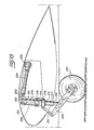
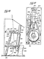
- the lateral undercarriage shown in FIGS. 15 to 18, of a main helicopter landing gear with lateral lift in the fuselage comprises a leg consisting of a box 251 and a barrel 252 mounted pivoting one on the other around a longitudinal axis 253.
- the box 251 has a generally triangular shape and has two legs 254 by each of which the box 251 is pivotally mounted around a portion of longitudinal axis 255, integral with the structure of the helicopter , as well as a yoke 256 receiving the fastener 257 provided at the upper end of the barrel 252 for the pivoting of the latter on the box 251 around the axis 253.
- the box 251 On its lower face, in the gear-out position, the box 251 also has a fastener 258, on which is articulated the end of the rod 259 of a jack such as that described above with reference to FIGS. 1 to 3, the cylinder 260 of which is articulated on a fastener 261 provided in the part bottom of the fuselage housing, in which the lander is housed in the retracted gear position, while the portions of longitudinal axes 255 are fixed substantially at mid-height in this housing.
- the barrel 252 of the leg consists of the body of a damper such as that previously described with reference to Figures 7 to 9, and there is a yoke 262, mounted on the lower end of the barrel 252, a cylinder 263 shock absorber protruding from this lower end and in which is received the shock absorber rod 264, the lower end 256 of which carries a rocket facing outwards and on which is mounted a wheel 266 equipped with a tire.
- the alignment of the wheel 266 relative to the undercarriage leg is ensured by a compass, the upper branch 267 and the lower branch 268 of which are pivotally mounted one on the other and respectively on the yoke 262 and on the part lower 265 and the rod 264, around longitudinal axes.
- the barrel 252 also has an anterior attachment 269 and a posterior attachment 270 on which the ends of rods 271 and 273 of struts respectively are hinged, such as that previously described with reference to FIG. 10, and whose cylinders 272 and 274 are respectively articulated on fasteners 275 and 276 secured to the structure of the helicopter, at a height intermediate between that of fastener 261 of the jack and that of the portions of longitudinal axes 255 in the extension l 'from one another, and respectively located in front and behind the transverse plane passing through the barrel 252.
- the box 251 and the leg barrel 252 are practically arranged one against the other, the longitudinal pivot axis 253 being positioned in the upper part of the housing, above the axis of linkage formed by the two portions of longitudinal axes 255, and the undercarriage is locked in this position retracted train by the jack itself locked in the rod out position.
- the descent of the undercarriage is ensured by controlling the re-entry of the rod 259 into the cylinder 260 of the jack, which causes the rotation of the casing 251 down around the lifting axis, and the descent of the barrel 252, maintained substantially in the same direction during its downward movement, thanks to the substantially deformable parallelogram mounting formed by the two counter-plugs, the box 251 and the barrel 252 with the vertical wall of the housing.
- the undercarriage is locked in the extended gear position by locking the cylinder in the retracted rod position, as shown in FIG. 6.
- the landing gear is lifted by controlling the opposite operations of output of rod 259 from cylinder 260 of the jack and of rotation in opposite direction, upwards, of box 251.
- the rod 264 of the shock absorber practically locks in the cylinder 263, and the absorption device of energy by plastic deformation housed between the cylinder 263 and the barrel 252 is triggered at the desired level of effort.
- the two struts 271-272 and 273-274 can operate simultaneously, in traction or in compression, depending on the direction of impact, in order to absorb a certain amount of energy and limit the lateral force transmitted to the cell.
- the two struts therefore tend to oppose any transverse rotation of the barrel 252 of the undercarriage around the longitudinal pivot axis 253 of the latter on the box 251, as long as the axial components urging these struts are not greater than the release velocity of the device for absorbing energy by plastic deformation which equips them.
- the landing gear which has just been described provides the same advantages as that described with reference to FIGS. 11 to 14, insofar as it also ensures the decoupling of the normal landing function from the impact protection function at high speed in all possible directions, this latter function being, in this case also, provided by different components according to the direction of the impact force.
- the invention is not limited to the two exemplary embodiments of landing gear which have just been described, but on the contrary extends to all trains fitted with at least one component, of the strut type, jack or damper, according to the invention.
- the train with rearward longitudinal lift can be fitted out in a wing train as in a fuselage train, and that it can be of the pendulum type, as described, or still of the direct sliding type, as is the case of the train described with reference to FIGS. 15 to 18, where the wheel is directly carried by the lower part of the damper rod, slidably mounted axially in the cylinder and in the barrel of the undercarriage leg.
- the lateral bracing of these trains can be provided by an internal lateral strut and / or an external lateral strut relative to the longitudinal plane passing through the undercarriage leg, these struts articulated on the leg either at above, or below the lifting axis.
- the longitudinal bracing can be ensured not only by a longitudinal jack placed behind the undercarriage leg, and locked in the retracted rod position, so as to be stressed in traction by the forces resulting from a forward impact, but also or alternatively by a longitudinal cylinder disposed at the front of the undercarriage, locked in the extended rod position , and stressed in compression by the force resulting from a forward impact.
- the longitudinal bracing can be ensured by a longitudinal cylinder placed at the rear of the leg, and locked in position rod extended, so as to be stressed in compression by a force resulting from an impact towards the front, and / or by a longitudinal jack arranged at the front of the leg and locked in position rod retracted, to be stressed in traction by the same type of effort.
- the longitudinal bracing is provided either by a front longitudinal strut and / or by a rear longitudinal strut, articulated one and / or the other on the leg above or below. below the lifting axis. If the cylinder attachment on the leg is located below the longitudinal lifting axis, the lateral bracing can be ensured by a cylinder locked in the extended rod position.
- the invention also relates to fixed landing gears, obtained by using only as hydraulic struts the jacks fitted to the landing gears mentioned above.
Description
La présente invention concerne des composants munis d'un dispositif d'absorption d'énergie par déformation plastique et/ou de limitation d'effort, ainsi que des trains d'atterrissage d'aérodynes équipés de tels composants.The present invention relates to components provided with a device for absorbing energy by plastic deformation and / or limiting force, as well as landing gear of aerodynes equipped with such components.
Plus particulièrement, l'invention a pour objet des composants hydrauliques et/ou mécaniques, tels que vérin, amortisseur et contre-fiche, destinés à l'équipement des trains d'atterrissage d'hélicoptères, afin de donner à cas derniers une capacité communément désignée par les termes d'«anti-crash».More particularly, the invention relates to hydraulic and / or mechanical components, such as actuator, shock absorber and strut, intended for the equipment of helicopter landing gear, in order to give latter cases a capacity commonly referred to as "anti-crash".
Par le brevet FR-A-1 549 884 et son certificat d'addition FR-A-2 010 302, on connaît déjà des dispositifs d'absorption d'énergie par déformation plastique et de limitation d'effort, comprenant des éléments de roulement, tels que des billes ou des galets, disposés entre deux organes télescopiques, de telle façon que lors d'un chic provoquant un déplacement télescopique des deux organes, les éléments de roulement provoquent une déformation plastique progressive de l'un au moins des deux organes télescopiques, du fait que les éléments de roulement sont serrés entre les organes télescopiques et sont réalisés en un matériau plus dur que le matériau constituant au moins l'organe qui se déforme, et dans lequel les éléments de roulement forment des rainures.By patent FR-A-1,549,884 and its certificate of addition FR-A-2,010,302, devices for absorbing energy by plastic deformation and limiting force are already known, comprising rolling elements , such as balls or rollers, arranged between two telescopic members, in such a way that during a knock-down causing a telescopic displacement of the two members, the rolling elements cause a progressive plastic deformation of at least one of the two members telescopic, because the rolling elements are clamped between the telescopic members and are made of a harder material than the material constituting at least the member which deforms, and in which the rolling elements form grooves.
Selon le certificat d'addition précité, les éléments de roulement sont maintenus en des positions prédéterminées dans des perforations ménagées dans un manchon, monté coaxialement entre les organes télescopiques, de forme générale cylindrique, et adapté pour se déplacer avec ces éléments de roulement et pour maintenir un espacement prédéterminé entre eux pendant leur roulement résultant d'un déplacement relatif des organes télescopiques, de sorte que ce manchon fasse office de cage pour les éléments de roulement.According to the aforementioned certificate of addition, the rolling elements are maintained in predetermined positions in perforations formed in a sleeve, mounted coaxially between the telescopic members, of generally cylindrical shape, and suitable for moving with these rolling elements and for maintain a predetermined spacing between them during their rolling resulting from a relative displacement of the telescopic members, so that this sleeve acts as a cage for the rolling elements.
Dans ces dispositifs, le montage des éléments de roulement serrés entre les organes télescopiques est choisi pour charger en compression ces éléments de roulement entre des portions, le plus souvent cylindriques, des organes télescopiques, de telle sorte que ces éléments de roulement excercent, dans la zone de contact avec les organes télescopiques, une pression de contact moyenne de valeur supérieure à !a pression de contact de déformation pour le matériau constituant au moins l'organe télescopique déformable, c'est-à-dire à la pression pour laquelle s'établit une répartition des contraintes menant à une déformation plastique dans la zone de contact, cette déformation plastique produisant une dissipation d'énergie élevée et localisée.In these devices, the mounting of the rolling elements clamped between the telescopic members is chosen to compressively compress these rolling elements between portions, most often cylindrical, of the telescopic members, so that these rolling elements exert, in the contact zone with telescopic members, an average contact pressure of value greater than the deformation contact pressure for the material constituting at least the deformable telescopic member, that is to say at the pressure for which establishes a distribution of the stresses leading to plastic deformation in the contact zone, this plastic deformation producing a high and localized energy dissipation.
La valeur de la dissipation d'énergie par unité de déplacement des organes télescopiques dépend du degré ou de la profondeur de la déformation plastique, qui elle-même dépend de la charge des éléments de roulement, c'est-à-dire de leur nombre, du degré de serrage, défini à partir de la valeur dont la dimension radiale ou diamètre des éléments de roulement est supérieure à la différence entre les dimensions radiales ou rayons externe et interne des organes télescopiques dans la zone de contact avant déformation. Cette veleur de la dissipation d'énergie dépend également des duretés relatives des matériaux constituant les éléments de roulement et les organes télescopiques.The value of the energy dissipation per unit of displacement of the telescopic members depends on the degree or the depth of the plastic deformation, which itself depends on the load of the rolling elements, i.e. their number , of the degree of tightening, defined from the value whose radial dimension or diameter of the rolling elements is greater than the difference between the radial dimensions or external and internal radii of the telescopic members in the contact zone before deformation. This velocity of energy dissipation also depends on the relative hardness of the materials constituting the rolling elements and the telescopic members.
L'utilisation de tels dispositifs fournit des caractéristiques d'absorption d'énergie pouvant être prévues avec une grande précision. On peut ainsi obtenir une absorption constante le long de la course des organes télescopiques, si l'épaisseur de ces derniers et le degré de serrage sont maintenus constants. Il est également possible que l'un des organes télescopiques voire les deux, soit réalisé avec une dimension interne ou externe qui varie de façon continue, de manière à obtenir une pièce convergente ou divergente par exemple de sorte que les éléments de roulement rencontrent une résistance respectivement croissante ou décroissante lors d'un déplacement télescopique des organes. De même, l'épaisseur de paroi de l'un des deux organes peut varier le long de ces derniers pour présenter une résistance variable à la déformation plastique.The use of such devices provides energy absorption characteristics which can be predicted with great precision. One can thus obtain a constant absorption along the course of the telescopic members, if the thickness of the latter and the degree of tightening are kept constant. It is also possible that one or both of the telescopic members is produced with an internal or external dimension which varies continuously, so as to obtain a convergent or divergent part for example so that the rolling elements meet resistance. respectively increasing or decreasing during a telescopic movement of the members. Likewise, the wall thickness of one of the two members can vary along the latter to present a variable resistance to plastic deformation.
Dans l'application décrite dans les brevets précités, de ces dispositifs d'absorption d'énergie à l'équipement des colonnes de direction de véhicules, un arbre de direction, comprenant deux parties montées télescopiquement l'une dans l'autre et solidaires en rotation par des goupilles assurant simultanément le positionnement axial de ces deux parties dans une position relative de fonctionnement normal, est monté en rotation dans une enveloppe de support constituée d'une portion tubulaire inférieure, solidaire du châssis du véhicule, et montée télescopiquement dans une portion tubulaire supérieure, reliée au tableau de bord par une ferrure à rupture unidirectionnelle au moyen de goupilles. Entre les parties des portions tubulaires inférieure et supérieure qui se chevauchent, sont engagées deux rangées annulaires, décalées axialement, d'éléments de roulement répartis angulairement autour de la portion tubulaire inférieure et interne, et décalés angulairement d'une rangée par rapport à l'autre. En réponse à un choc axial, sollicitant en compression l'un ou l'autre des organes télescopiques, et développant sur les goupilles des efforts suffisants pour les cisailler, les deux parties constitutives de l'arbre de direction s'écrasent télescopiquement, de même que les deux portions tubulaires de l'enveloppe de support, ce qui provoque une déformation plastique de l'une au moins des portions tubulaires, et donc une dissipation importante d'énergie, de sorte que les efforts transmis par l'enveloppe support sont limités à une valeur très inférieure à celle du choc axial.In the application described in the aforementioned patents, of these energy absorption devices for equipping vehicle steering columns, a steering shaft, comprising two parts mounted telescopically one inside the other and integral in rotation by pins simultaneously ensuring the axial positioning of these two parts in a relative position of normal operation, is rotatably mounted in a support envelope consisting of a lower tubular portion, integral with the chassis of the vehicle, and mounted telescopically in a portion upper tubular, connected to the dashboard by a unidirectional breaking fitting by means of pins. Between the parts of the lower and upper tubular portions which overlap, are engaged two annular rows, axially offset, of rolling elements distributed angularly around the lower and inner tubular portion, and angularly offset by one row relative to the other. In response to an axial shock, stressing in compression one or the other of the telescopic members, and developing on the pins sufficient forces to shear them, the two constituent parts of the steering shaft are telescopically crushed, likewise that the two tubular portions of the support envelope, which causes plastic deformation of at least one of the tubular portions, and therefore a significant dissipation of energy, so that the forces transmitted by the support envelope are limited at a value much lower than that of the axial shock.
Par le brevet FR-A-2 110 078, on connaît également des dispositifs d'absorption d'énergie, dont la structure présente de nombreuses analogies avec celles des dispositifs précédemment considérés, puisqu'ils comprennent des moyens d'impression, se présentant également sous la forme de billes, galets, etc... mais aussi sous la forme d'un anneau, des moyens destinés à effectuer un déplacement relatif desdits moyens d'impression et d'un organe d'absorption d'énergie, se présentant sous la forme d'un manchon.From patent FR-A-2 110 078, energy absorption devices are also known, the structure of which has many analogies with those of the devices previously considered, since they include printing means, also presenting in the form of balls, rollers, etc., but also in the form of a ring, means intended to effect a relative displacement of said printing means and of an energy absorbing member, appearing under the shape of a sleeve.
Les moyens destinés à effectuer un déplacement relatif comporte un organe de support, faisant face à l'organe d'absorption d'énergie, et portant, par exemple dans une chambre radiale présentant au moins une paroi conique en regard de ce dernier, les moyens d'impression, afinque ces derniers accompagnent le déplacement de l'organe support par rapport à l'organe d'absorption d'énergie, et soient repoussés dans ce dernier.The means intended to effect a relative displacement comprises a support member, facing the energy absorption member, and carrying, by example in a radial chamber having at least one conical wall facing the latter, the printing means, so that the latter accompany the movement of the support member relative to the energy absorption member, and are repelled in this last.
Mais le fonctionnement de ces dispositifs est fondamentalement différent de ceux préalablement considérés ci-dessus, dans la mesure où l'organe d'absorption d'énergie est un organe déformable élastiquement qualifié d'organe élastomère dans ce brevet FR-A-2 110 078, et agencé de manière à subir une déformation élastique localisée par compression ainsi qu'une compression et un allongement élastiques répartis latéralement par rapport à la zone de déformation élastique localisée.However, the operation of these devices is fundamentally different from those previously considered above, insofar as the energy absorption member is a deformable member which is elastically qualified as an elastomer member in this patent FR-A-2 110 078 , and arranged so as to undergo localized elastic deformation by compression as well as elastic compression and elongation distributed laterally with respect to the localized elastic deformation zone.
L'organe d'absorption d'énergie, constitué par un manchon présentant des qualités élastomères, et réalisé notamment en caoutchoucs naturels ou au silicone, permet la réalisation d'un dispositif procurant les avantages d'un amortisseur hydraulique ou pneumatique, puisque les chocs et à-coups peuvent être absorbés, tout en ne présentant qu'une structure de prix de revient et de poids réduits.The energy absorption member, constituted by a sleeve having elastomeric qualities, and produced in particular from natural rubbers or silicone, allows the production of a device providing the advantages of a hydraulic or pneumatic damper, since the shocks and jolts can be absorbed, while presenting only a structure of cost price and reduced weight.
Il est, par ailleurs, bien connu que les trains d'atter- risage d'aérodynes sont équipés de divers composants, tels que des vérins, des amortisseurs et des contre-fiches, que remplissent une fonction principale hydraulique et/ou mécanique, et qui comprennent chacun un élément tubulaire à l'intérieure duquel est reçu un élément télescopique, immobilisé vis-à-vis de l'élément tubulaire dans au moins une position d'utilisation normale du composant, par au moins un dispositif de verrouillage.It is also well known that aircraft landing gear is equipped with various components, such as jacks, shock absorbers and struts, which fulfill a main hydraulic and / or mechanical function, and which each comprise a tubular element inside which is received a telescopic element, immobilized with respect to the tubular element in at least one position of normal use of the component, by at least one locking device.
Il en est ainsi, par exemple, du vérin décrit dans DE-A-2 313 821, qui est un vérin hydraulique destiné à manoeuvrer un atterrisseur, et qui comprend un mécanisme interne de verrouillage de la tige du vérin en position sortie par rapport au cylindre du vérin. Le mécanisme interne de verrouillage comporte des griffes élastiques portées par le piston ou le cylindre du vérin, un redan de blocage porté respectivement par le cylindre ou le piston du vérin, et un piston de verrouillage, coulissant respectivement dans le cylindre ou autour de la tige, et rappelé élastiquement en position de verrouillage des griffes lorsque celles-ci sont bloquées derrière le redan. Ce mécanisme de verrouillage est à libération hydraulique, car le piston de verrouillage est repoussé à l'encontre du ressort de rappel par la pression de manoeuvre du vérin, du fait que la chambre du ressort est en communication avec la chambre du vérin dans laquel règne la pression la plus faible.This is the case, for example, with the cylinder described in DE-A-2 313 821, which is a hydraulic cylinder intended to operate a undercarriage, and which comprises an internal mechanism for locking the rod of the cylinder in the extended position relative to the cylinder of the cylinder. The internal locking mechanism comprises elastic claws carried by the piston or cylinder of the jack, a locking step carried respectively by the cylinder or the piston of the jack, and a locking piston, sliding respectively in the cylinder or around the rod. , and resiliently returned to the claw locking position when they are blocked behind the step. This locking mechanism is hydraulically released, because the locking piston is pushed back against the return spring by the actuating pressure of the jack, because the spring chamber is in communication with the jack chamber in which reigns the lowest pressure.
Dans des conditions anormales d'atterrisage, lorsqu'un tel vérin est amené à subir un effort supérieur à la charge de rupture du mécanisme de verrouillage, la tige tend à rentrer dans le cylindre, après la rupture du mécanisme de verrouillage, avec une vitesse très supérieure à celle pour laquelle sont dimensionnés les orifices d'alimentation et de vidange des chambres du vérin. Il se produit alors un blocage de la tige et du piston dans le cylindre, et une élévation de la pression interne pouvant conduire à l'éclatement du vérin. Mais, jusqu'à l'éclatement, le vérin transmet intégralement la charge anormalement élevée qu'il subit à la structure de l'aérodyne, ce qui entraîne l'endommagement de celle-ci, avec les risques qui en résultent pour les personnes embarquées dans l'aérodyne.Under abnormal landing conditions, when such a jack is made to undergo a force greater than the breaking load of the locking mechanism, the rod tends to re-enter the cylinder, after the breaking of the locking mechanism, with a speed much higher than that for which the supply and drain ports of the actuator chambers are dimensioned. There then occurs a blockage of the rod and of the piston in the cylinder, and an increase in the internal pressure which can lead to the bursting of the jack. But, until bursting, the jack fully transmits the abnormally high load it undergoes to the structure of the aerodyne, which leads to its damage, with the resulting risks for those on board in the aerodyne.
Le problème à la base de l'invention consiste à tirer partie de toute possibilité de course relative entre la tige et le cylindre d'un tel vérin, pour assurer une absorption et une dissipation d'énergie qui permet au vérin de ne transmettre à la structure de l'aérodyne qu'une fraction admissible de la charge trop élevée qui le sollicite, dans des conditions d'utilisation anormales.The problem underlying the invention consists in taking advantage of any possibility of relative travel between the rod and the cylinder of such a jack, in order to ensure absorption and dissipation of energy which allows the jack to not transmit to the structure of the aerodyne that an admissible fraction of the too high load which requests it, under abnormal conditions of use.
La présente invention a pour but d'adapter des mécanismes d'absorption d'énergie par déformation plastique, du type de ceux décrits dans le FR-A-1 549 884 et son addition FR-A-2 010 302, dans des composants remplissant une fonction principale hydraulique et/ou mécanique, tels qu'un vérin de manoeuvre et/ou de contreventement, du type décrit dans DE-A-2 313 821, ou un amortisseur oléopneumatique, qui constitue déjà par lui-même un dispositif d'absorption et de dissipation d'énergie, ou encore une contre-fiche de contreventement d'un élément principal, de sorte que ces composants puissent remplir une fonction supplémentaire d'absorption d'énergie et/ou de limitation d'effort, dans un but de sécurité et de protection d'une structure à laquelle ils sont associés, et comprenant des parties auxquelles des efforts violents, résultant de chocs et d'à-coups portés sur la structure, ne doivent pas être transmis sans amortissement, atténuation ou limitation.The present invention aims to adapt energy absorption mechanisms by plastic deformation, of the type described in FR-A-1 549 884 and its addition FR-A-2 010 302, in filling components. a main hydraulic and / or mechanical function, such as an actuating and / or bracing cylinder, of the type described in DE-A-2 313 821, or an oleopneumatic damper, which already constitutes by itself a device for absorption and dissipation of energy, or a bracing strut of a main element, so that these components can fulfill an additional function of energy absorption and / or limitation of effort, for a purpose security and protection of a structure with which they are associated, and comprising parts to which violent forces, resulting from shocks and jolts applied to the structure, must not be transmitted without damping, attenuation or limitation.
Il en est ainsi des aérodynes, dont les cellules doivent être, autant que possible protégées en cas d'accident, afin d'assurer au minimum la survie des personnels embarqués, et, éventuellement aussi, la préservation de la majeure partie de l'aérodyne, et l'invention a également pour but de concevoir des trains d'atterrissage d'aérodynes, en particulier d'hélocop- tères, équipés de composants selon l'invention, et présentant une capacité «anti-crash».This is the case with aerodynes, whose cells must be protected as much as possible in the event of an accident, in order to ensure at least the survival of the personnel on board, and, possibly also, the preservation of most of the aerodyne. , and the invention also aims to design landing gear for aerodynes, in particular helicopter landing machines, equipped with components according to the invention, and having an “anti-crash” capacity.
A cet effet, un composant selon l'invention, remplissant une fonction principale hydraulique et/ou mécanique, du type vérin, amortisseur ou contre-fiche, et comprenant un élément tubulaire à l'intérieur duquel est reçu un élément télescopique immobilisé vis-à-vis de l'élément tubulaire dans au moins une position d'utilisation par au moins un dispositif de verrouillage, se caractérise en ce qu'il comprend également un dispositif d'absorption d'énergie par déformation plastique et/ou de limitation d'effort, comportant un ensemble d'éléments de roulement maintenu par une cage et interposé avec serrage entre un organe interne et un organe externe montés l'un dans l'autre, et dont au moins l'organe externe est un organe à charge de déformation plastique prédéterminée, lesdits organes étant susceptibles de coulisser l'un dans l'autre après rupture d'un élément frangible à charge de rupture prédéterminée et compris dans le dispositif de verrouillage, de sorte que les éléments de roulement provoquent, de façon ensoi connue, une dissipation d'énergie par déformation plastique d'au moins l'organe externe, qui est solidaire de l'élément tubulaire, l'élément télescopique constituant l'organe interne qui entraîne la cage de retenue des éléments de roulement.To this end, a component according to the invention, fulfilling a main hydraulic and / or mechanical function, of the jack, damper or strut type, and comprising a tubular element inside which is received a telescopic element immobilized vis-à-vis screw of the tubular element in at least one position of use by at least one locking device, is characterized in that it also comprises a device for absorbing energy by plastic deformation and / or limiting force, comprising a set of rolling elements held by a cage and interposed with clamping between an internal member and an external member mounted one inside the other, and of which at least the external member is a member with deformation load predetermined plastic, said members being capable of sliding into one another after rupture of a frangible element with predetermined breaking load and included in the locking device, so that the rolling elements pro evoke, in a manner so known, energy dissipation by plastic deformation of at least the external member, which is integral with the tubular element, the telescopic element constituting the internal member which drives the cage for retaining the elements of rolling.
Par camparaison avec le vérin décrit dans DE-A-2 313 821, un composant du type vérin selon l'invention permet, à partir de la position tige sortie et verrouillée, de profiter de toute la course possible de la tige dans le cylindre pour faire coopérer les éléments de roulement et les organes interne et externe du dispositif d'absorption d'énergie par déformation plastique, et donc pour dissiper une quantité importante d'énergie, dès que le fonctionnement du dispositif d'absorption d'énergie est déclenché par la rupture de l'élément frangible que comporte le dispositif de verrouillage du vérin.By camparaison with the cylinder described in DE-A-2 313 821, a component of the cylinder type according to the invention makes it possible, from the extended and locked rod position, to take advantage of all the possible stroke of the rod in the cylinder for make the rolling elements and the internal and external members of the energy absorption device cooperate by plastic deformation, and therefore to dissipate a significant amount of energy, as soon as the operation of the energy absorption device is triggered by the rupture of the frangible element that comprises the locking device of the jack.
Le seuil de rupture de l'élément frangible correspond à la charge maximale que le vérin peut transmettre à la structure de l'aérodyne sans l'endommager, cette charge maximale étant, bien entendu, supérieure aux charges subies par le vérin dans des conditions normales d'utilisation, et qui peuvent être transmises à la structure. Le seuil de rupture ainsi choisi pour l'élément frangible permet d'éviter tout blocage de la tige dans le cylindre et de commander une absorption d'énergie dès que cela est nécessaire pour que la structure ne soit pas surchargée.The breaking threshold of the frangible element corresponds to the maximum load that the cylinder can transmit to the structure of the aerodyne without damaging it, this maximum load being, of course, greater than the loads undergone by the cylinder under normal conditions of use, and which can be transmitted to the structure. The breaking threshold thus chosen for the frangible element makes it possible to avoid any blockage of the rod in the cylinder and to control an energy absorption as soon as this is necessary so that the structure is not overloaded.
Selon l'invention, l'organe externe déformable plastiquement est constitué soit par l'élément tubulaire lui-même, soit par un fourreau, doublant l'élément tubulaire à l'intérieur de ce dernier, sur au moins une partie de sa longueur, avec un jeu radial suffisant pour admettre la déformation plastique provoquée par les éléments de roulement, et amovible pour permettre la remise en état du composant par remplacement du fourreau et d'au moins l'élément frangible.According to the invention, the plastically deformable external member is constituted either by the tubular element itself, or by a sheath, doubling the tubular element inside the latter, over at least part of its length, with sufficient radial clearance to admit the plastic deformation caused by the rolling elements, and removable to allow the component to be repaired by replacing the sheath and at least the frangible element.
Selon l'invention, l'élément tubulaire peut être constitué par le corps, de forme générale cylindrique, d'une contre-fiche comprenant également une tige, constituant l'élément télescopique, montée coulissante dans le corps et immobilisée vis-à-vis de ce dernier dans une position initiale dans laquelle une partie de la tige pénètre dans le corps, au moyen d'au moins un boulon à tige partiellement filetée, vissé dans un taraudage radial traversant le corps à son extrémité traversée par la tige, et tel que l'extrémité de la tige du boulon pénètre dans un perçage radial de la tige de contre-fiche et constitue simultanément le dispositif de verrouillage et l'élément frangible à charge de rupture prédéterminée, la cage de retenue des éléments de roulement étant solidarisée sur l'extérieur de la partie de la tige interne au corps et les éléments de roulement étant en appui radial vers l'intérieur contre la tige et vers l'extérieur dans une empreinte de l'organe déformable plastiquement, constitué soit par le corps soit par le fourreau retenu par la tige partiellement filetée du ou des boulons contre la paroi interne du corps à l'extrémité de ce dernier traversée par la tige de la contre-fiche.According to the invention, the tubular element can be constituted by the body, of generally cylindrical shape, of a strut also comprising a rod, constituting the telescopic element, slidably mounted in the body and immobilized vis-à-vis of the latter in an initial position in which a part of the rod penetrates into the body, by means of at least one bolt with partially threaded rod, screwed into a radial thread passing through the body at its end through which the rod passes, and such that the end of the bolt rod penetrates into a radial bore in the strut rod and simultaneously constitutes the locking device and the frangible element at a predetermined breaking load, the cage for retaining the rolling elements being secured to the outside of the part of the rod internal to the body and the rolling elements being in radial support inwards against the rod and outwards in an imprint of the plastically deformable member, const ituted either by the body or by the sheath retained by the partially threaded rod of the bolt (s) against the internal wall of the body at the end of the latter crossed by the rod of the strut.
Selon que la tige de la contre-fiche est rigidement liée au corps respectivement en position rentrée, en position à demi-rentrée et en position sortie, le dispositif d'absorption d'énergie par déformation plastique de la contre-fiche peut être utilisé dans les cas d'une sollicitation supérieure au seuil de rupture de l'élémentfrangible respectivement en traction seulement, en traction ou en compression, et en compression seulement.Depending on whether the rod of the strut is rigidly connected to the body respectively in the retracted position, in the half-retracted position and in the extended position, the device for absorbing energy by plastic deformation of the strut can be used in cases of stress greater than the breaking threshold of the frangible element respectively in tension only, in tension or in compression, and in compression only.
Selon l'invention, l'élément tubulaire peut encore être constitué par le cylindre d'un vérin hydraulique, comprenant une tige constituant l'élément télescopique, montée coulissante dans le cylindre et guidée dans ce dernier par un piston porté à son extrémité interne au cylindre, la tige du vérin étant immobilisée dans le cylindre dans au moins une position d'utilisation normale du vérin par un dispositif de verrouillage à griffes élastiques dont les têtes sont bloquées contre un redan sur la paroi interne du cylindre par au- moins un piston de verrouillage, et dont les pieds sont solidaires d'un talon radial, constituant l'élément frangible à charge de rupture prédéterminée, et présentant une couronne extérieure séparée par une section de rupture d'une couronne intérieure entraînée par la tige de vérin en même temps que la cage des éléments de roulement portée autour de l'extrémité de la tige interne aucylindre de vérin.According to the invention, the tubular element can also be constituted by the cylinder of a hydraulic cylinder, comprising a rod constituting the telescopic element, slidably mounted in the cylinder and guided in the latter by a piston carried at its internal end to the cylinder, the rod of the cylinder being immobilized in the cylinder in at least one position of normal use of the cylinder by a locking device with elastic claws whose heads are locked against a step on the internal wall of the cylinder by at least one piston of locking, and the feet of which are integral with a radial heel, constituting the frangible element with a predetermined breaking load, and having an outer ring separated by a breaking section from an inner ring driven by the cylinder rod at the same while the bearing element cage is carried around the end of the internal cylinder cylinder rod.
Dans une forme de réalisation préférée du vérin selon l'invention, les éléments de roulement sont retenus radialement vers l'intérieur par un anneau monté coulissant entre la cage retenant les éléments de roulement et la tige de vérin, et présentant sur sa face extérieure une gorge servant au logement des éléments de roulement, en position d'utilisation du vérin, et se raccordant par une rampe inclinée à une portion cylindrique, l'anneau étant sollicité élastiquement vers la couronne extérieure de l'élément frangible-pour provoquer, à la suite de la rupture de ce dernier, la sortie des éléments de roulement de la gorge et leur déplacement sur la rampe inclinée puis sur la portion cylindrique de l'anneau, lors d'un déplacement relatif de la cage entraînant les éléments de roulement et entraînée par la tige vis-à-vis de l'anneau, maintenu en butée contre la couronne extérieure de l'élément frangible avant que d'être entraîné avec la tige par la couronne intérieure de l'élément frangible, de sorte que les éléments de roulement sont déplacés radialement vers l'extérieur, en saillie par rapport à la cage, et sont susceptibles de provoquer des déformations plastiques de l'organe à charge de déformation plastique prédéterminée.In a preferred embodiment of the jack according to the invention, the rolling elements are retained radially inwards by a ring mounted to slide between the cage retaining the rolling elements and the jack rod, and having on its outer face a groove used for housing the rolling elements, in the position of use of the jack, and connected by an inclined ramp to a cylindrical portion, the ring being urged elastically towards the outer crown of the frangible element - to cause, at the following the rupture of the latter, the exit of the rolling elements from the groove and their displacement on the inclined ramp then on the cylindrical portion of the ring, during a relative displacement of the cage driving the rolling elements and driven by the rod vis-à-vis the ring, held in abutment against the outer crown of the frangible element before being driven with the rod by the inner crown of the frangible element, so that the rolling elements are moved radially outwards, projecting relative to the cage, and are capable of causing plastic deformations of the member under load of predetermined plastic deformation.
Selon l'invention, et dans le cas où l'organe déformable plastiquement est le cylindre du vérin lui-même, un chambrage est prévu à l'extrémité du cylindre entournant la cage, les éléments de roulement et l'anneau, en position d'utilisation normale du vérin, et s'étend axialement sur une distance autorisant la venue des éléments de roulement en saillie par rapport à la cage, à la suite de la rupture de l'élément frangible et d'un déplacement initial de la tige dans le cylindre du vérin.According to the invention, and in the case where the plastically deformable member is the cylinder of the jack itself, a recess is provided at the end of the cylinder surrounding the cage, the rolling elements and the ring, in position d normal use of the jack, and extends axially over a distance allowing the coming of the rolling elements projecting relative to the cage, following the rupture of the frangible element and an initial displacement of the rod in the cylinder of the jack.
Dans le cas où l'absorption d'énergie désirée conduit à une définition du cylindre du vérin incompatible avec sa fonction normale, celui-ci peut être doublé par un fourreau interne déformable, moulé avec un jeu radial suffisant pour admettre la déformation provoquée par les éléments de roulement.In the case where the desired energy absorption leads to a definition of the cylinder of the cylinder incompatible with its normal function, this can be doubled by a deformable internal sheath, molded with a sufficient radial clearance to admit the deformation caused by the rolling elements.
Selon que l'élément frangible appartient au dispositif de verrouillage immobilisant la tige vis-à-vis du cylindre de vérin respectivement en position rentrée ou en position sortie, le dispositif d'absorption d'énergie par déformation plastique et/ou de limitation d'effort du vérin est sollicité respectivement en traction ou en compression par un effort qui peut être inférieur, égal ou supérieur au seuil de rupture de l'élément frangible.Depending on whether the frangible element belongs to the locking device immobilizing the rod with respect to the cylinder of the cylinder respectively in the retracted position or in the extended position, the energy absorption device by plastic deformation and / or limitation of effort of the jack is stressed respectively in tension or in compression by an effort which can be less than, equal to or greater than the breaking point of the frangible element.
Selon l'invention, l'élément tubulaire du composant peur également être constitué par le corps, présentant au moins une partie de forme générale cylindrique, d'un amortisseur comprenant également un cylindre, constituant l'élément télescopique, au moins partiellement logé dans la partie de forme générale cylindrique du corps, et immobilisé en position d'utilisation dans ce corps par au moins un boulon à tige partiellement filetée traversant un alésage radial ménagé dans le corps vissée dans un talon radial du cylindre, de façon à constituer simultanément le dispositif de verrouillage et l'élément frangible, une tige d'amortisseur étant montée coulissante avec étanchéité dans le cylindre de l'amortisseur, qui renferme de plus un dispositif élastique d'absorption d'énergie, susceptible de rappeler la tige en position initiale dans le cylindre, ainsi qu'un dispositif de dissipation d'énergie par laminage d'un volume d'huile hydraulique déplacé dans l'amortisseur partout déplacement relatif de la tige et du cylindre.According to the invention, the tubular element of the component can also be constituted by the body, having at least a part of generally cylindrical shape, of a damper also comprising a cylinder, constituting the telescopic element, at least partially housed in the generally cylindrical part of the body, and immobilized in the position of use in this body by at least one bolt with partially threaded rod passing through a radial bore formed in the body screwed into a radial heel of the cylinder, so as to simultaneously constitute the device locking device and the frangible element, a damper rod being slidably mounted with sealing in the damper cylinder, which also contains an elastic energy absorption device, capable of returning the rod to the initial position in the cylinder, as well as a device for dissipating energy by rolling a volume of hydraulic oil displaced in the shock absorber everywhere relative displacement f of the rod and cylinder.
Dans une forme préférée de réalisation, le talon radial externe, dans lequel est vissée l'extrémité filetée de la tige du ou des boulons, constitue simultanément la cage des éléments de roulement, retenue sur la paroi externe du cylindre de l'amortisseur. De préférence, les éléments de roulement sont en appui radial vers l'intérieur dans une gorge pratiquée sur la paroi externe du cylindre, et la cage, en position fixe par rapport à cette gorge, amène les éléments de roulement à coopérer avec l'organe déformable plastiquement constitué, dans ce cas également, soit par le corps de l'amortisseur lui-même, soit par un fourreau retenu par au moins le ou les boulons contre la paroi interne du corps.In a preferred embodiment, the external radial heel, into which the threaded end of the rod or bolts is screwed, simultaneously constitutes the cage of the rolling elements, retained on the external wall of the damper cylinder. Preferably, the rolling elements are radially inwardly supported in a groove formed on the external wall of the cylinder, and the cage, in a fixed position relative to this groove, causes the rolling elements to cooperate with the member. plastically deformable, also in this case, either by the body of the damper itself, or by a sleeve retained by at least the bolt (s) against the internal wall of the body.
On sait qu'en cas de choc ou d'impact à vitesse élevéesur un amortisseur, le laminage n'est plus possible et la tige est bloquée dans le corps de l'amortisseur. En conséquence, on choisit selon l'invention un seuil de déclenchement du dispositif d'absorption d'énergie par déformation plastique de l'amortisseur qui est supérieur aux. efforts subis par l'amortisseur dans des conditions de fonctionnement normales mais inférieur à un effort qui endommagerait la structure supportée par lamortisseur en cas de blocage de la tige dans le cylindre de ce dernier.It is known that in the event of a shock or impact at high speed on a shock absorber, rolling is no longer possible and the rod is blocked in the body of the shock absorber. Consequently, according to the invention, a triggering threshold of the energy absorption device by plastic deformation of the damper is chosen which is greater than. forces undergone by the shock absorber under normal operating conditions but less than a force which would damage the structure supported by the shock absorber in the event of the rod blocking in the latter's cylinder.
Les composants selon l'invention présentent l'avantage que la course utile de leurs dispositifs d'absorption d'énergie par déformation plastique et/ou de limitation d'effort est la même que celle de leur tige lorsque ces composants remplissent leur fonction principale, tout en ayant les avantages d'un montage en série. La longueur d'un composant selon l'invention n'est donc pas modifiée par l'adjonction de la fonction supplémentaire d'absorption d'énergie et/ou de limitation d'effort par rapport aux composants analogues de l'art antérieur.The components according to the invention have the advantage that the useful stroke of their devices for absorbing energy by plastic deformation and / or limiting force is the same as that of their rod when these components fulfill their main function, while having the advantages of a series connection. The length of a component according to the invention is therefore not modified by the addition of the additional function of energy absorption and / or limitation of effort compared to analogous components of the prior art.
Les trains d'atterrissage principaux pour aérodynes, en particulier pour hélicoptères, selon l'invention, comprenant, pour chaque atterrisseur, une jambe dont le fût est équipé d'un amortisseur muni d'une tige dont l'extrémité inférieure, en position d'atterrissage, est reliée à au moins un organe de contact avec le sol, tel qu'une roue, la jambe étant maintenue en position d'utilisation, sensiblement verticale, pour l'atterrissage et le décollage, par un dispositif de contreventement latéral et un dispositif de contreventement longitudinal, articulé chacun d'une part, sur la jambe et d'autre part, sur la structure d'aérodyne, se caractérisent en ce que leur amortisseur est un amortisseur selon l'invention, dont le corps constitue directement le fût de la jambe d'atterrisseur, et dont l'élément frangible à charge de rupture prédéterminée se rompt pour tout effort transmis par le cylindre d'amortisseur au fût de la jambe, qui est supérieur à un seuil témoignant d'un blocage de la tige d'amortisseur dans le cylindre, par suite de conditions anormales d'atterrissage, de sorte que le fonctionnement du dispositif d'absorption d'énergie par déformation plastique de l'amortisseur soit déclenché, et que la composante verticale, introduite dans la tige d'amortisseur et dont la valeur est susceptible d'endommager la structure de l'aérodyne, d'un effort sollicitant l'atterrisseur, ne soit pas transmise au fût de la jambe.The main landing gear for aerodynes, in particular for helicopters, according to the invention, comprising, for each undercarriage, a leg whose shaft is equipped with a shock absorber provided with a rod whose lower end, in position d landing, is connected to at least one member of contact with the ground, such as a wheel, the leg being maintained in the use position, substantially vertical, for landing and take-off, by a lateral bracing device and a longitudinal bracing device, each articulated on the one hand, on the leg and on the other hand, on the aerodyne structure, are characterized in that their damper is a damper according to the invention, the body of which directly constitutes the shaft of the landing gear leg, and the frangible element of which at a predetermined breaking load ruptures for any force transmitted by the shock absorber cylinder to the barrel of the leg, which is above a threshold indicating a blockage of the rod d 'damper in the cylinder, due to abnormal landing conditions, so that the operation of the energy absorption device by plastic deformation of the damper is triggered, and that the vertical component, introduced into the rod shock absorber and whose value is likely to damage the structure of the aerodyne, of a force requesting the undercarriage, is not transmitted to the barrel of the leg.
De préférence, le dispositif de contreventement latéral et/ou le dispositif de contreventement longitudinal des trains d'atterrissage selon l'invention comprennent au moins une contre-fiche et/ou un vérin selon l'invention, dont les dispositifs d'absorption d'énergie par déformation plastique respectifs se déclenchent lorsque la composante de l'effort, respectivement supportée par la contre-fiche et/ou le vérin selon la direction latérale ou longitudinale du contreventement que cette contre-fiche ou ce vérin assure, est supérieur au seuil de rupture de l'élément frangible, ce seuil correspondant à une valeur maximale admissible de cette compostante de l'effort dans des conditions normales d'atterrissage.Preferably, the lateral bracing device and / or the longitudinal bracing device of the landing gear according to the invention comprise at least one strut and / or a jack according to the invention, including the absorption devices energy by respective plastic deformation is triggered when the component of the force, respectively supported by the strut and / or the jack in the lateral or longitudinal direction of the bracing that this strut or this jack provides, is greater than the threshold of rupture of the frangible element, this threshold corresponding to a maximum admissible value of this compost of the force under normal landing conditions.
Avantageusement, le vérin de contreventement que comprend l'un des dispositifs de contreventement constitue simultanément un vérin de manoeuvre, commandant la rotation de la jambe d'atterrisseur autour d'un axe de relevage, entre une position «train rentré» et une position «train sorti», ainsi, éventuellement que le verrouillage de la jambe dans ces deux positions, de sorte que les trains d'atterrissage selon l'invention soient du type dit relevable.Advantageously, the bracing cylinder which comprises one of the bracing devices simultaneously constitutes a maneuvering cylinder, controlling the rotation of the undercarriage leg about a lifting axis, between a "retracted gear" position and a " undercarriage ”, as well as possibly locking the leg in these two positions, so that the landing gears according to the invention are of the so-called lifting type.
Les trains d'atterrissage relevables, selon l'invention, peuvent être du type dit à «balancier», dont la tige d'amortisseur est articulée, à son extrémité inférieure, sur un balancier portant à son extrémité postérieure l'organe de contact avec le sol, tel qu'une roue, et dont l'extrémité antérieure est montée pivotante sur une branche de compas reliant le balancier à une chape qui entoure le fût de la jambe et sur laquelle la branche de compas est elle-même montée pivotante. Les trains relevables à balancier selon l'invention se caractérisent en ce que la chape et le fût sont solidarisés en rotation par au moins un second élément frangible, à charge de rupture prédéterminée inférieure à la charge de rupture de l'élément frangible du dispositif de contreventement latéral, de sorte que si la composante transversale d'un effort sollicitant l'organe de contact avec le sol, et donc le balancier, dépasse une valeur maximale admissible, le second élément frangible se casse et désolidarise en rotation le fût et la chape, ce qui permet l'orientation de l'ensemble constitué par l'organe de contact avec le sol, le balancier et la tige d'amortisseur dans la direction de cette composante, qui est ensuite absorbée par le dispositif d'absorption d'énergie par déformation plastique du dispositif de contreventement latéral et/ou de l'amortisseur, si la valeur de cette composante est supérieure au seuil de l'élément frangible correspondant. Ce type de train d'atterrissage relevable à balancier peut être à relevage longitudinal. Dans ce cas le fût de la jambe de chaque atterrisseur est solidaite d'un axe de relevage transversal, monté pivotant sur la structure de l'aérodyne, et, selon l'invention, la manoeuvre de chaque atterrisseur et son contreventement longitudinal sont assurés par un vérin disposée selon une direction sensiblement longitudinale, le fût de la jambe étant monté pivotant sur l'axe de relevage autour d'un tourillon longitudinal, et le contreventement latéral étant assuré par une contre-fiche, disposée dans un plan transversal, de sorte qu'en dehors des manoeuvres du train, les jambes d'atterrisseurs puissent pivoter, à partir de la position train sortie, respectivement autour de l'axe de relevage transversal et du tourillon longitudinal, après les déclenchements respectifs des dispositifs d'absorption d'énergie par déformation plastique du vérin et de la contre-fiche.The liftable landing gears, according to the invention, can be of the so-called “pendulum” type, the damper rod of which is articulated, at its lower end, on a pendulum carrying at its rear end the contact member with the ground, such as a wheel, and the front end of which is pivotally mounted on a branch of compass connecting the pendulum to a yoke which surrounds the shank of the leg and on which the branch of compass is itself pivotally mounted. The tilting liftable trains according to the invention are characterized in that the yoke and the barrel are secured in rotation by at least one second frangible element, at a predetermined breaking load less than the breaking load of the frangible element of the device. lateral bracing, so that if the transverse component of a force urging the contact member with the ground, and therefore the pendulum, exceeds a maximum admissible value, the second frangible element breaks and disconnects in rotation the barrel and the yoke , which allows the orientation of the assembly constituted by the contact member with the ground, the pendulum and the shock absorber rod in the direction of this component, which is then absorbed by the energy absorption device by plastic deformation of the lateral bracing device and / or of the shock absorber, if the value of this component is greater than the threshold of the corresponding frangible element. This type of liftable landing gear with pendulum can be lifted longitudinally. In this case, the barrel of the leg of each undercarriage is secured to a transverse lifting axis, pivotally mounted on the structure of the aerodyne, and, according to the invention, the maneuvering of each undercarriage and its longitudinal bracing are ensured by a jack arranged in a substantially longitudinal direction, the shank of the leg being pivotally mounted on the lifting axis around a longitudinal pin, and the lateral bracing being provided by a counter-plug, arranged in a transverse plane, so that apart from the train maneuvers, the undercarriage legs can pivot, from the extended gear position, respectively around the transverse lifting axis and the longitudinal journal, after the respective actuations of the absorption devices energy by plastic deformation of the jack and the counter-plug.
Les trains d'atterrissage relevables selon l'invention peuvent également être du type dit à relevage transversal, dont le fût de la jambe de chaque atterrisseur est solidaire d'un axe de relevage longitudinal monté pivotant sur la structure de l'aérodyne. Selon l'invention, de tels trains se caractérisent en ce que la manoeuvre de chaque atterrisseur et son contreventement latéral sont assurés par un vérin disposé dans un plan sensiblement transversal, et en ce que le fût de la jambe est monté pivotant sur l'axe de relevage autour d'un trourillon transversal, et que le contreventement longitudinal est assuré par une contre-fiche disposée selon une direction sensiblement longitudinale, de sorte qu'en dehors des manoeuvres du train, les jambes d'atterrisseurs puissent pivoter, à partir de la position train sorti, respectivement autour de l'axe de relevage longitudinal et du tourillon transversal après les déclenchements respectifs des dispositifs d'absorption d'énergie par déformation plastique du vérin et de la contre-fiche.The liftable landing gears according to the invention can also be of the so-called transverse lift type, the shaft of the leg of each undercarriage is integral with a longitudinal lift axis pivotally mounted on the structure of the aerodyne. According to the invention, such trains are characterized in that the operation of each undercarriage and its lateral bracing are ensured by a jack arranged in a substantially transverse plane, and in that the shank of the leg is pivotally mounted on the axis lifting around a transverse swivel, and that the longitudinal bracing is provided by a strut arranged in a substantially longitudinal direction, so that outside the train maneuvers, the landing gear legs can pivot, from the position with the gear extended, respectively around the longitudinal lifting axis and the transverse journal after the respective trips of the energy absorption devices by plastic deformation of the jack and the counter-plug.
Enfin, l'invention a également pour objet des trains d'atterrissage relevables, du type se relevant latéralement dans le fuselage, et comprenant pour chaque atterrisseur un vérin commandant la manoeuvre de la jambe autour d'un axe de relevage longitudinal solidaire de la structure de l'aérodyne. De tels trains selon l'invention se caractérisent en ce que la jambe d'atterrisseur est constituée d'un caisson, de forme générale triangulaire, pivotant autour de l'axe de relevage, et sur lequel est d'une part montée pivotant l'extrémité supérieure du fût de la jambe et d'autre part articulée une extrémité du vérin, de sorte que les dispositifs d'absorption d'énergie par déformation plastique de l'amortisseur et du vérin puissent être successivement utilisés pour l'absorption d'une composante verticale importante d'un effort sollicitant l'organe de contact avec le sol, et en ce que le contreventement latéral et le contreventement longitudinal sont assurés par une contre-fiche inclinée vers l'avant et une contre-fiche inclinée vers l'arrière de l'aérodyne par rapport au fût de la jambe.Finally, the invention also relates to liftable landing gear, of the type which is raised laterally in the fuselage, and comprising for each undercarriage a jack controlling the operation of the leg around a longitudinal lifting axis integral with the structure of aerodyne. Such trains according to the invention are characterized in that the undercarriage leg consists of a box, of generally triangular shape, pivoting around the lifting axis, and on which is on the one hand pivotally mounted the upper end of the barrel of the leg and on the other hand articulated one end of the jack, so that the devices for absorbing energy by plastic deformation of the shock absorber and of the jack can be successively used for the absorption of a significant vertical component of a force requesting the contact member with the ground, and in that the lateral bracing and the longitudinal bracing are provided by a strut inclined towards the front and a strut inclined towards the rear of aerodyne with respect to the barrel of the leg.
La présente invention sera mieux comprise à l'aide des exemples particuliers de réalisation qui sont décrits ci-après, à titre non limitatif, en référence aux figures annexées dans lesquelles:
- la figure 1 est une vue schématique d'un vérin muni d'un dispositif d'absorption d'énergie par déformation plastique et/ou de limitation d'effort destiné à être sollicité en traction,
- les figures 2 et 3 sont des vues en coupe partielle d'une extrémité du vérin selon la figure 1, respectivement avant et après rupture de l'élément frangible,
- la figure 4 est une vue analogue à la figure 1 pour un vérin dont le dispositif d'absorption d'énergie par déformation plastique et/ou de limitation d'effort est destiné à être sollicité en compression,
- les figures 5
et 6 sont des vues analogues aux figures 2 et 3 pour le vérin selon la figure 4, - les figures 7 et 8 sont des vues en coupe partielle d'un amortisseur muni d'un dispositif d'absorption d'énergie par déformation plastique et/ou de limitation d'effort pour l'équipement, notamment d'une jambe d'atterrisseur,
- la figure 9 est une vue en coupe selon IX-IX de la figure 8,
- la figure 10 est une vue en coupe partielle d'une contre-fiche muni d'un dispositif d'absorption d'énergie par déformation plastique et/ou de limitation d'effort,
- la figure 11 est une vue en perspective d'un atterrisseur latéral d'un train d'atterrissage principal à balancier et à relevage longitudinal vers l'arrière, équipé d'un vérin, d'un amortisseur et d'une contre-fiche selon les figures précédentes,
- les figures 12, 13 et 14 sont des vues de côté de l'atterrisseur selon la figure 11 respectivement en position «train rentré», «train sorti» sous charge statique et «train sorti» après ou au cours d'une séquence d'absorption d'énergie et limitation d'effort consécutive à un atterrissage avec une vitesse verticale anormalement élevée,
- ' les figures 15 et 16 sont des vues de face, respectivement en position «train rentré» et «train sorti» d'un atterrisseur latéral d'un train d'atterrissage principal de fuselage et à relevage latéral,
- la figure 17 est une vue de côté de l'atterrisseur selon XVII-XVII de la figure 15, et
- la figure 18 est une vue de face de l'atterrisseur des figures 15 à 17 sorti, après ou au cours d'une séquence d'absorption d'énergie et/ou de limitation d'effort consécutive à un atterrissage avec une vitesse verticale anormalement élevée.
- FIG. 1 is a schematic view of a jack fitted with an energy absorption device by plastic deformation and / or of force limitation intended to be stressed in traction,
- FIGS. 2 and 3 are views in partial section of one end of the jack according to FIG. 1, respectively before and after rupture of the frangible element,
- FIG. 4 is a view similar to FIG. 1 for a jack whose device for absorbing energy by plastic deformation and / or limiting force is intended to be stressed in compression,
- FIGS. 5 and 6 are views similar to FIGS. 2 and 3 for the jack according to FIG. 4,
- Figures 7 and 8 are partial sectional views of a shock absorber provided with an energy absorption device by plastic deformation and / or force limitation for the equipment, in particular a landing gear leg ,
- FIG. 9 is a sectional view along IX-IX of FIG. 8,
- FIG. 10 is a partial section view of a counter-plug provided with an energy absorption device by plastic deformation and / or force limitation,
- FIG. 11 is a perspective view of a lateral undercarriage of a main landing gear with balance wheel and with rearward longitudinal lift, equipped with a jack, a shock absorber and a strut according to the previous figures,
- Figures 12, 13 and 14 are side views of the undercarriage according to Figure 11 respectively in position "gear retracted", "gear out" under static load and "gear out" after or during a sequence of energy absorption and effort limitation following a landing with an abnormally high vertical speed,
- FIGS. 15 and 16 are front views, respectively in the “retracted gear” and “extended gear” position of a side undercarriage of a main fuselage undercarriage and with side lift,
- FIG. 17 is a side view of the undercarriage according to XVII-XVII of FIG. 15, and
- FIG. 18 is a front view of the undercarriage of FIGS. 15 to 17 taken out, after or during a sequence of energy absorption and / or of limitation of effort following a landing with an abnormally vertical speed high.
En référence aux figures 1 à 3, le vérin est constitué d'un cylindre 1, dans lequel est montée coulissante avec étanchéité une tige 2, guidée à l'extrémité 3 du cylindre 1 traversée par la tige 2 par une bague et au moins un joint d'étanchéité dynamique (non représentés). L'autre extrémité du cylindre 1, présentant une portion cylindrique de plus grand diamètre interne 4, est fermée par un embout creux 5. Cet embout 5 porte, à une extrémité, une attache 6, et présente à son autre extrémité un filetage externe sur une partie cylindrique 7 par laquelle l'embout 5 est monté autour de l'extrémité de la portion 4 du cylindre 1, et se trouve retenu sur cette dernière grâce à une bague 8 taraudée, retenue sur le cylindre 1 par une butée axiale 9 disposée dans une gorge sur la face extérieure du cylindre 1, un joint d'étanchéité étant interposé entre la partie 7 de l'embout 5 et la portion 4 du cylindre 1. La tige 2 est munie, à son extrémité externe au cylindre 1, d'une attache 10, et à son extrémité interne au cylindre 1, présentant une portion de plus petit diamètre externe 11, d'un piston 12, équipé de joints d'étanchéité dynamique 13, coulissant sur la paroi interne du cylindre 1 et guidant la tige 2 dans ses déplacements vis-à-vis de ce dernier. Sur la portion de plus petit diamètre externe 11 de la tige 2, sont successivement disposés, de l'épaulement radial 14 vers l'extrémité obturée et extérieurement filetée 15 délimitant la portion 11 de la tige 2, le talon radial interne 16 du pied d'un ensemble de griffes élastiques 17, destinées à s'encliqueter élastiquement derrière un redan prévu dans l'extrémité 3 du cylindre 1, pour assurer le verrouillage du vérin hydraulique en position «tige sortie» (de façon analogue à ce qui est décrit ci-après pour le verrouillage en position «tige rentrée», comme représenté sur la figure 2), puis le piston 12, une cage 18 pour des billes 19, une entretoise 20, la couronne intérieure 21 du talon radial interne du pied d'un ensemble de griffes élastiques 23, et enfin un écrou de retenue 24 vissé sur le filetage de l'extrémité obturée 15. La couronne intérieure 21 est séparée par une section à charge de rupture par cisaillement prédéterminée de la couronne extérieure 22 du talon radial interne, qui constitue ainsi un élément frangible, désigné ci-après par le terme de fusible mécanique. La cage 18 présente une partie cylindrique de plus petit diamètre interne 25, radialement disposée entre le piston 12 et la portion 11 de la tige 2, ainsi qu'une partie cylindrique de plus grand diamètre interne 26, présentant des perçages radiaux centrés dans un plan diamétral et dans chacun desquels est reçue une bille 19, et entourant un ressort 27 disposé lui-même autour de l'entretoise 20. Le ressort 27 prend appui par l'une de ses extrémités contre la partie radiale de la cage 18 séparant les deux parties cylindriques 25 et 26 de cette dernière et, par son autre extrémité, contre un anneau 28. L'anneau 28, de forme extérieure cylindrique, monté coulissant autour de l'entretoise 20, se trouve muni d'une queue 29 d'appui contre la couronne extérieure 22 du fusible mécanique, et présente sur sa face externe une gorge 30, de section en partie circulaire raccordée par une surface conique à une surface externe cylindrique 31 de l'anneau 28, dirigée vers la face de ce dernier contre laquelle prend appui le ressort 27.Referring to Figures 1 to 3, the cylinder consists of a cylinder 1, in which is slidably mounted with sealing a
Le blocage de la tige 2 en position rentrée dans le cylindre 1 est assuré par l'encliquetage élastique des têtes des griffes 23 derrière un redan, constitué par l'extrémité d'un manchon 32, s'étendant dans le cylindre 1, radialement disposé entre un partie d'extrémité de la portion 4 de ce dernier et l'ensemble des griffes 23, et maintenu en position par son épaulement radial externe 33 serré entre un épaulement ra- diai de l'embout 5 et l'extrémité de la portion 4 du cylindre 1. Le verrouillage des griffes 23 dans cette position tige rentrée est assuré par un dispositif d'arrêt, comprenant un piston de verrouillage 34, monté coulissant avec étanchéité dans un alésage de l'embout 5, grâce au joint d'étanchéité 35, et poussé par un ressort 36 prenant appui contre le fond fermé de l'embout 5, vers l'intérieur du cylindre 1, jusqu'à venir se loger à l'intérieur des têtes des griffes 23, pour empêcher ces dernières de se dégager de l'extrémité du manchon 32. Le dispositif d'arrêt est associé à un dispositif de contrôle de verrouillage comportant un taquet 37, monté pivotant par une extrémité dans une chambre médiane 38 de l'embout 5, et dont l'autre extrémité est appliquée contre la tête d'une des griffes 23.The locking of the
Celles-ci, lors du verrouillage, déplacent le taquet 37 lequel actionne un contacteur 39. Un voyant placé au poste de pilotage permet à l'équipage de contrôler le verrouillage tige rentrée.These, during locking, move the
La mise sous pression de la chambre 38 de l'embout 5 au travers du raccord 40 d'alimentation en huile hydraulique repousse le piston 34 vers le fond dudit embout, contre le ressort 36 et assure successivement le déverrouillage des griffes 23, un déplacement initial de la tige 2 avec les griffes 23 libérées dans le cylindre 1, vers la position tige sortie, et l'alimentation en huile sous pression de la chambre définie par le cylindre 1, la tige 2 et le piston 12, ce qui provoque la sortie de la tige, qui est verrouillée en fin de course, en position tige sortie, par coopération des griffes 17 avec un dispositif d'arrêt analogue à celui venant d'être décrit, mais disposé dans l'extrémité 3 du cylindre 1, traversée par la tige 2, et donc dans lequel le piston de verrouillage est un piston annulaire.The pressurization of the chamber 38 of the nozzle 5 through the hydraulic
Le vérin hydraulique qui vient d'être décrit, à verrouillage mécanique et à déverrouillage hydraulique dans les deux positions en fin de course, est destiné à être solidarisé par l'attache 6 de son cylindre 1 et l'attache 10 de sa tige 2 à deux éléments, que le vérin doit en certaines circonstances déplacer l'un par rapport à l'autre et, en d'autres circonstances maintenir rigidement positionnés l'un par rapport à l'autre, lorsqu'il est en configuration tige rentrée, à l'encontre d'une charge sollicitant l'un des deux éléments. Lorsque cette dernière est une charge provoquant la sollicitation en traction du vérin, avec une valeur supérieure à un effort maximum admissible, pouvant être transmis par le vérin de l'un à l'autre des éléments, sans risque d'endommager l'un de ces derniers, il est clair que le vérin doit permettre de limiter l'effort transmis à une valeur acceptable prédéterminée, et donc d'absorber et de dissiper une certaine quantité d'énergie en excès. Ceci est obtenu en calibrant la section de rupture à charge de cisaillement prédéterminée, qui sépare les deux couronnes intérieure 21 et extérieure 22 de l'élément frangible, à la valeur de l'effort maximum de traction pouvant être transmis, constituant la valeur de déclenchement du fonctionnement du dispositif d'absorption d'énergie par déformation plastique, dont est équipé le vérin.The hydraulic cylinder which has just been described, with mechanical locking and with hydraulic unlocking in the two end-of-travel positions, is intended to be secured by the
Dans le cas où l'effort de traction sur le vérin atteint la valeur de déclenchement prédéterminée, la section de rupture se rompt et la couronne intérieure 21 se sépare de la couronne extérieure 22 du talon des griffes 23, maintenues en place par le dispositif d'arrêt. La tige 2 commence un déplacement de sortie du cylindre 1, tandis que le ressort 27 se détend en maintenant l'anneau 28 en butée par sa queue 29 contre la couronne extérieure 22. Cependant, comme la cage 18 est entraînée avec la tige 2 par l'intermédiaire de l'entretoise 20, de la couronne intérieure 21 et de l'écrou 24, la partie 26 de la cage 18 est donc déplacée axialement par rapport à l'anneau 28, et provoque la sortie des billes 19 hors de la rainure 30, grâce à la surface conique qui la raccorde à la surface externe cylindrique 31 de l'anneau 28, sur laquelle les billes 19 viennent reposer. Le dispositif d'éjection des billes 19 ainsi réalisé permet de faire saillir ces dernières dans le chambrage 41 délimité par la portion d'extrémité 4 de plus grand diamètre interne du cylindre 1, après la rupture de l'élément frangible. Sous l'effet de la traction, la tige 2 se déplace ensuite dans le cylindre 1, en entraînant les billes 19, positionnées par la cage 18 de façon à prendre appui radialement vers l'intérieur sur la partie cylindrique 31 de l'anneau 28. Comme les billes 19 ont un diamètre supérieur, d'une valeur déterminée, à la différence entre le rayon interne du cylindre 1, dans sa partie médiane de plus petit diamètre interne, et le rayon de la surfacé cylindrique 31 de l'anneau 28, lorsqu'elles arrivent à la fin du chambrage 41, elles déforment plastiquement le cylindre 1 du vérin, sur le restant de la course de la tige 2 dans le cylindre 1, comme cela est représenté sur la figure 3, ce qui provoque une absorption et une dissipation d'énergie permettant de limiter à une valeur acceptable l'effort transmis par le vérin, tout au moins tant que dure la déformation.In the event that the tensile force on the jack reaches the predetermined tripping value, the rupture section breaks and the
La quantité d'énergie absorbée est déterminée notamment par l'importance de l'empreinte des billes 19, par leur nombre et par l'épaisseur du cylindre 1, ainsi que par les duretés relatives des matériaux choisis pour réaliser ces éléments. Si l'absorption d'énergie doit être constante, la déformation sera constante tout le long de la course des billes 19, en utisilant un cylindre de section et d'épaisiseur constantes, mais si l'on désire une absorption variable le long de la course des billes 19, le cylindre peut être d'épaisseur variable adapté au profil désiré.The amount of energy absorbed is determined in particular by the size of the imprint of the
Si les effets désirés conduisent à une définition du cylindre 1 incompatible avec l'exercice de sa fonction normale de cylindre d'un vérin hydraulique d'une cylindrée adaptée, compte tenu de la pression hydraulique régnant dans le circuit hydraulique d'alimentation, aux efforts à développer pour manoeuvrer sur une course voulue et bloquer en position les deux éléments auxquels le vérin est relié, le cylindre 1 peut être doublé par un fourreau interne, déformable plastiquement dans les mêmes conditions, et moulé avec un jeu radial suffisant pour admettre la déformation plastique provoquée par les billes 19.If the desired effects lead to a definition of the cylinder 1 incompatible with the exercise of its normal function of cylinder of a hydraulic cylinder of a suitable displacement, taking into account the hydraulic pressure prevailing in the hydraulic supply circuit, to the forces to be developed to maneuver over a desired stroke and lock in position the two elements to which the jack is connected, the cylinder 1 can be doubled by an internal sleeve, plastically deformable under the same conditions, and molded with a sufficient radial clearance to admit the deformation plastic caused by the
Le vérin venant d'être décrit a pour avantage que la course des billes 19 est pratiquement la même que celle de la tige 2 dans le cylindre 1, tout en présentant les avantages d'un montage en série d'un dispositif combiné remplissant les fonctions de vérin et d'absorption d'énergie et/ou de limitation d'effort. La longueur du vérin n'est donc pas modifiée par l'adjonction d'une fonction supplémentaire d'absorption d'énergie et/ou de limitation d'effort à sa fonction principale.The jack just described has the advantage that the stroke of the
Par ailleurs, il faut noter qu'une membrane tarée ou un clapet de surpression 42 est disposé dans l'extrémité 3 du cylindre 1, traversée par la tige 2, de façon à autoriser la purge vers l'extérieur du vérin de la chambre annulaire définie entre le cylindre 1 et la tige 2, par le piston 12 et l'extrémité 3 du cylindre 1, de sorte que l'huile remplissant cette chambre ne s'oppose pas au déplacement du piston 12 avec la tige 2 dans le cylindre 1, après rupture de l'élément frangible et lors du déplacement des billes 19 déformant plastiquement le cylindre 1.In addition, it should be noted that a tared membrane or a
Sur les figures 4 à 6, on a représenté un vérin muni d'un dispositif d'absorption d'énergie et/ou de limitation d'effort destiné à être sollicité en compression, à partir de la position tige sortie, par un effort supérieur à une valeur maximale admissible.In FIGS. 4 to 6, there is shown a jack provided with an energy absorption and / or force limitation device intended to be stressed in compression, from the extended rod position, by a greater force. to a maximum allowable value.
Les éléments de ce vérin identiques à ceux du vérin décrit en référence aux figures 1 à 3 sont repérés par les mêmes références.The elements of this cylinder identical to those of the cylinder described with reference to Figures 1 to 3 are identified by the same references.
Il faut noter, en particulier, que la tige 2 est identique, mais que l'ensemble des pièces qu'elle porte sur sa partie d'extrémité 11, de plus petit diamètre externe, est disposé en sens opposé, de sorte que les griffes 23, munies à leur pied d'uh talon radial constituant l'élément frangible par ses couronnes intérieure 21 et extérieure 22, puissent être verrouillées par un dispositif d'arrêt reçu dans l'embout 53 de l'extrémité du cylindre 51 traversée par la tige 2. C'est donc la couronne intérieure 21 qui est serrée entre l'épaulement 14 de la tige 2 et l'entretoise 20, tandis que le talon radial interne 16 des griffes 17 est serré entre le piston 12 et l'écrou 24, la cage 18, les billes 19, l'anneau 28 et le ressort 27 occupant vis-à-vis du piston 12 et de la couronne intérieure 21 les mêmes positions relatives que précédemment, et l'ensemble constituant un système d'éjection des billes 19 en saillie dans le chambrage délimité par la portion de plus grand diamètre interne 54 du cylindre 51, après rupture de l'élément frangible.It should be noted, in particular, that the
Le dispositif d'arrêt, reçu dans l'embout 53, comprend un piston de verrouillage 84 annulaire, monté coulissant avec étanchéité à l'intérieur d'un alésage de l'embout 53 grâce au joint 85 et autour de la tige 2 grâce aux joints 87, et sollicité par un ressort 86 de sorte que le prolongement axial 89 du piston 84 vienne bloquer les griffes 23 derrière le redan du manchon 32, dont le talon radial 33 est serré contre l'extrémité de la portion 54 du cylindre 51 par l'embout 53. Ce dernier présente une chambre médiane 38, dans laquelle est monté pivotant le taquet 37, sollicitant le contacteur 39 lors du verrouillage des griffes 23, ainsi qu'un raccord d'alimentation 90 en huile hydraulique pour commander le déverrouillage hydraulique et la manoeuvre du vérin.The stop device, received in the
Le fonctionnement de ce vérin est en tout point analogue à celui du vérin décrit en référence aux figures 1 à 3, mis à part que le dispositif d'absorption d'énergie et/ou de limitation d'effort est déclenché par un effort de compression supérieur à la charge de rupture en cisaillement prédéterminée de la section séparant les couronnes extérieure 22 et intérieure 21 de l'élément frangible, et s'exerçant sur le vérin verrouillé en configuration tige sortie. En conséquence, la membrane tarée ou le clapet de surpression symbolisé en 42 est prévu sur l'embout 55 de l'extrémité du cylindre 51 non traversée par la tige 2, pour autoriser la vidange du cylindre 51 lors de la rentrée de la tige 2 après rupture de l'élément frangible.The operation of this jack is in all respects analogous to that of the jack described with reference to FIGS. 1 to 3, except that the device for absorbing energy and / or limiting the force is triggered by a compression force greater than the predetermined shear breaking load of the section separating the outer 22 and inner 21 crowns of the frangible element, and acting on the locked cylinder in the outgoing rod configuration. Consequently, the tared membrane or the pressure relief valve symbolized at 42 is provided on the
En référence aux figures 7 à 9, un amortisseur oléopneumatique selon l'invention comporte une tige 101, montée coulissante avec étanchéité dans un cylindre 102 sensiblement vertical, et guidée grâce aux bagues 103 et 104. La bague 103 est disposée dans une gorge ménagée sur la face interne d'un fourreau cylindrique 105, retenu dans un chambrage prévu à l'extrémité inférieure du cylindre 102 par un écrou 106, tandis que la bague 104 est retenue contre un épaulement radial 107, qui est usiné dans un bossage présenté par le cylindre 102 sur sa paroi interne, sensiblement à mi-hauteur, par une butée axiale annulaire 108, dans laquelle sont vissés des écrous 109 traversant des alésages radiaux percés dans le cylindre 102. La tige 101 renferme, à sa partie inférieure, une chambre de gaz sous pression 110, par exemple une chambre d'azote, séparée par un piston séparateur 111, monté coulissant avec étanchéité dans la tige 101, d'un volume d'huile remplissant le reste de la tige 101 ainsi que la partie du cylindre 102 située au-dessus de la bague 104, le cylindre 102 étant fermé par un couvercle 112 vissé dans son extrémité supérieure. La tige 101 porte, dans sa portion d'extrémité supérieure, un dispositif de dissipation d'énergie par laminage d'huile 113, représenté de façon symbolique, car ce dispositif peut être constitué par tour dispositif de laminage connu: orifices permanents, du type diaphragme, obturables par clapet, éventuellement piloté en fonction de la pression ou de la vitesse de déplacement de la tige 101 dans le cylindre 102, les orifices étant à sections constantes ou variables en fonction de la vitesse et/ou du sens de déplacement de la tige dans le cylindre, ou encore orifice central ménagé dans une paroi transversale de la tige 101 et traversé par une contre tige de section variable portée par le couvercle 112, de sorte que la section de passage varie en fonction de la course de la tige dans le cylindre.With reference to FIGS. 7 to 9, an oleopneumatic damper according to the invention comprises a
En l'absence de charge sur l'amortisseur, la chambre de gaz sous pression 110 tend à repousser l'huile de la tige 101 dans le cylindre 102 au travers du dispositif le laminage 113, ce qui assure la sortie de la tige 101 hors du cylindre 102, jusqu'à la position maximale tige sortie représentée sur la figure 7, dans laquelle l'épaulement radial externe 114 de la tige 101 vient en butée contre le fourreau 105.In the absence of a load on the damper, the
Sous charge, la tige 101 est poussée vers l'intérieur du cylindre 102, de sorte que l'huile du cylindre 102 est chassée dans la tige 101, au travers du dispositif 113 assurant par laminage la dissipation d'une certaine quantité d'énergie, et vient comprimer la chambre de gaz 110, qui absorbe élastiquement une autre quantité d'énergie, restituée au moins partiellement par la suite pour ramener la tige 101 dans une position d'équilibre sous la charge dans le cylindre 102.Under load, the
Le cylindre 102 est lui-même reçu coaxialement dans un corps 115, de forme générale cylindrique, présentant une portion supérieure de plus petit diamètre interne 116, dans laquelle le cylindre 102 est positionné en rotation grâce à une raînure pratiquée dans le corps 116 et à une vis 117 dans le cylindre 102. Au voisinage de l'extrémité inférieure du corps 115, une pluralité de boulons 118, dont l'extrémité de la tige est filetée, traversent chacun un alésage radial ménagé dans le corps 115 ainsi qu'un perçage dans la partie inférieure de plus grand diamètre interne d'un fourreau déformable plastiquement 119, doublant le corps 115 de long de la paroi interne de la portion de plus grand diamètre interne de ce dernier, avec un jeu radial suffisant pour permettre la déformation plastique de ce fourreau 119 par des billes 120, retenues par une cage 121 vissée sur la face externe du cylindre 102 par des boulons 122, et dans laquelle se visse l'extrémité filetée de la tige des boulons 118, laquelle est séparée de la partie non filetée par une section à charge de rupture en cisaillement prédéterminée, ou section frangible, de sorte que la tige des boulons 118 constitue un fusible mécanique pour les déplacements axiaux du cylindre 102 dans le corps 115. La partie non filetée de la tige des boulons 118 traverse également un anneau de centrage 123, disposé entre le fourreau 119 et la cage 121. Comme cela apparaît sur les figures 7 et 8, les billes 120 sont en appui radial vers l'intérieur dans une gorge ménagée autour du cylindre 102, et leur diamètre est supérieur à la différence entre le rayon de la partie de plus petit diamètre interne du fourreau 119 et le rayon à fond de gorge du cylindre 102.The
Pour les cas où la tige 101 doit être guidée en translation dans le cylindre 102 sans rotation par rapport à ce dernier, un compas, dont une branche (non représentée) est reliée à la partie inférieure de la tige 101, a son autre branche 124 articulée sur une chape 125 qui est retenue autour de la partie inférieure du corps 115, entre un épaulement 126 de ce dernier et un écrou 127, et solidaire en rotation du corps 115 grâce à un boulon 128, dont la tige présente une partie non filetée, traversant un alésage radial de la chape 125, séparée d'une partie d'extrémité filetée et vissée dans le corps 115 par une section à charge de rupture en cisaillement prédéterminée, ou section frangible, de sorte que la tige du boulon 128 constitue un fusible mécanique pour les rotations de la tige 101 dans le corps 115.For cases where the
En cas de choc ou de charge exercé sur la tige 101 et tendant à rentrer cette dernière dans le cylindre 102 avec une vitesse telle que la section de passage de l'huile au travers du dispositif de laminage 113 est nettement insuffisante, le laminage ne peut s'effectuer dans de bonnes conditions, compte tenu des faibles débits possibles, et la tige 101 est comme bloquée dans le cylindre 102. L'amortisseur se comporte alors pratiquement comme une bielle rigide de longueur constante, transmettant au corps 115, et donc à la masse suspendue, l'intégralitéé de l'effort auquel est soumise la tige 101 à son extrémité inférieure.In the event of an impact or load exerted on the
Lorsque cet effort transmis atteint la valeur de déclenchement du dispositif d'absorption d'énergie et/ ou de limitation d'effort, dont est équipé l'amortisseur, c'est-à-dire la valeur prédéterminée de la charge de rupture en cisaillement des tiges des boulons 118, ces dernières se rompent et le cylindre 102 coulisse dans le corps 115 en entraînant les billes 120 par l'intermédiaire de la cage 121. Les billes 120 déforment plastiquement le fourreau 119 de long de ses génératrices, ce qui provoque une absorption et une dissipation d'énergie, qui peut être ajustée à une valeur choisie, dans les mêmes conditions que précédemment, en jouant sur le nombre des billes, leur diamètre, leur dureté et celle du fourreau, ainsi que sur l'épaisseur et le profil de ce dernier. L'effort transmis de la tige 101 au corps 115 peut ainsi être limité à une valeur acceptable.When this transmitted force reaches the trigger value of the energy absorption and / or force limitation device, with which the shock absorber is fitted, that is to say the predetermined value of the breaking shear load rods of the
Lorsque la tige 101 est sollicitée en torsion par rapport au cylindre 102, et donc par rapport au corps 115, au-delà de la charge de rupture de la tige du boulon 128, cette dernière se casse, puisque le moment de torsion est transmis par le compas à la chape 125, et la chape 125 peut ensuite librementtourner autour du corps 115.When the
On constate que l'amortisseur présente comme avantage que la course du dispositif d'absorption d'énergie n'est que peu inférieure à la longueur du corps 115, et que celle-ci n'est pas modifiée par l'adjonction de la fonction supplémentaire d'absorption d'énergie et/ou de limitation d'effort.It is noted that the damper has the advantage that the stroke of the energy absorption device is only slightly less than the length of the
Comme cela apparaît sur la figure 9, le corps 115 peut présenter, sur sa paroi interne, des rainures longitudinales 129 dans lesquelles s'effectuera la déformation plastique du fourreau 119, par ailleurs en appui radialement vers l'extérieur sur les bossages du corps 115 séparant les rainures 129 les unes des autres.As shown in FIG. 9, the
La contre-fiche représentée sur la figure 10 est constituée d'un corps 151, de forme cylindrique, dont une extrémité est fermée par un embout 152, vissé dans le corps 151, et muni d'un dispositif de liaison mécanique tel qu'une rotule 153, et dont l'autre extrémité est traversée par une tige 154. Cette tige 154, dont l'extrémité externe au cylindre 151 porte également un embout 155, muni d'une rotule 156, et vissé dans la tige 154 de manière réglable pour ajuster la longueur de la contre-fiche à une dimension voulue, grâce à sa partie filetée 157, présente à l'intérieur du cylindre 151, une portion cylindrique de plus petit diamètre interne 158, extérieurement filetée, se prolongeant par une portion d'extrémité conique 159. Sur cette dernière prennent appui des billes 160, retenues dans une cage tubulaire 161, vissée sur le filetage de la portion cylindrique 158 de la tige 154, et coulissant à l'intérieur d'un fourreau déformable plastiquement 162, serti sensiblement en son milieu autour de la partie des billes 160 qui dépasse de la cage 161, et doublant le corps 151 à l'intérieur de ce dernier avec un jeu radial suffisant pour permettre sa déformation plastique, avec absorption et dissipation d'énergie, lorsque les billes 160 sont déplacées avec la tige 154 par l'intermédiaire de la cager 161, dans l'une ou autre direction dans le corps 151. Pour favoriser le guidage lors d'un déplacement en direction tige sortie ou en direction tige rentrée, la cage 161 présente respectivement une partie cylindrique d'extrémité 163 ou 164, coulissant à l'intérieur du fourreau 162 avant sa déformation. Le fourreau 162 est maintenu en position axiale dans le cylindre 151 par des boulons 165, à tige partiellement filetée, vissée dans un alésage du cylindre 151 à son extrémité voisine de l'embout 152, et par des boulons 166, à tige partiellement filetée vissée dans un alésage radial du cylindre 151 à son extrémité traversée par la tige 154, les parties non filetées des tiges des boulons 165 et 166 traversant des perçages ménagés dans les extrémités en regard du fourreau 162. La partie non filetée de la tige des boulons 166 présente de plus une section frangible, à charge de rupture en cisaillement prédéterminée, de sorte qu'elle constitue un fusible mécanique. L'extrémité de ces tiges pénètrent dans un perçage radial de la tige 154, de sorte que les boulons 166 assurent le blocage axial en position initiale de la tige 154 dans le cylindre 151.The strut shown in FIG. 10 consists of a body 151, of cylindrical shape, one end of which is closed by an
La contre-fiche est donc constituée d'une tige 154 bloquée en position demi-sortie dans le cylindre 151 par des fusibles mécaniques, dont la rupture s'effectue à une valeur prédéterminée de la sollicitation en compression ou en traction s'exerçant sur la contre-fiche, et correspondant à la valeur de déclenchement du dispositif d'absorption d'énergie et/ou de limitation d'effort par déformation plastique du fourreau 162 par les billes 160.The counter-plug therefore consists of a
Il est clair que dans cette configuration, la course du dispositif d'absorption d'énergie est limitée sensiblement à la moitié de la longueur du corps 151.It is clear that in this configuration, the travel of the energy absorption device is limited substantially to half the length of the body 151.
Mais si le dispositif d'absorption d'énergie de la contre-fiche est destiné à n'être sollicité respectivement qu'en compression ou qu'en traction, la tige 154 peut être bloquée en position initiale respectivement tige sortie ou tige rentrée par les boulons 166, de sorte que pratiquement toute la longueur du cylindre 151 puisse être utilisée comme course du dispositif d'absorption d'énergie. Bien entendu le fourreau 162 est alors serti sur les billes 160 par son extrémité correspondant.However, if the energy absorption device of the strut is intended to be stressed only in compression or in traction respectively, the
Si on le désire, il est également possible de supprimer le fourreau 162, qui présente l'avantage de pouvoir être remplacé après déformation, et de réaliser la contre-fiche de sorte que les billes 160 déforment plastiquement le cylindre 151.If desired, it is also possible to eliminate the sheath 162, which has the advantage of being able to be replaced after deformation, and to produce the counter-plug so that the balls 160 plastically deform the cylinder 151.
Le vérin, l'amortisseur et la contre-fiche qui viennent d'être décrits en référence aux figures 1 à 10 sont bien adaptés à l'équipement des trains d'atterrissage des aérodynes,et en particulier des hélicoptères, auxquels ces composants permettent de donner une aptidute «anti-crash».The jack, the shock absorber and the strut which have just been described with reference to FIGS. 1 to 10 are well suited to the equipment of landing gear of aerodynes, and in particular of helicopters, to which these components make it possible to give an “anti-crash” ability.
En utilisation normale, et avant l'atterrissage, les jambes des atterrisseurs doivent être maintenues rigidement en position par rapport à une cellule à laquelle elles sont liées directement ou indirectement, et ce n'est qu'après le décollage que les atterrisseurs peuvent être, éventuellement, relevés soit dans la voilure, soit dans le fuselage de l'aérodyne, soit encore dans des moignons d'ailes ou ailettes ou des caissons de fuselage, prévus latéralement à la partie inférieure de ce dernier. Le positionnement rigide des jambes d'atterrisseur, qui portent l'organe de contact avec le sol, tel qu'une roue, un patin ou un ski, par l'intermédiaire d'un dispositif de suspension, par exemple un amortisseur oléopneumatique logé dans le fût de la jambe d'atterrisseur et absorbant l'énergie d'impact, est généralement assuré au moyen de contre-fiches, mécaniques ou hydrauliques, de longueur constante ou télescopique, et de vérins, hydrauliques ou mécaniques voire même électriques, susceptibles de faire office d'organes de contreventement, comme une contre-fiche, et/ou d'organes de manoeuvre.In normal use, and before landing, the legs of the undercarriages must be held rigidly in position relative to a cell to which they are linked directly or indirectly, and it is only after takeoff that the undercarriages can be, optionally, raised either in the wing, or in the fuselage of the aerodyne, or even in stubs of wings or fins or fuselage boxes, provided laterally at the bottom of the latter. The rigid positioning of the undercarriage legs, which carry the contact member with the ground, such as a wheel, a skate or a ski, by means of a suspension device, for example an oleopneumatic damper housed in the shaft of the undercarriage and absorbing impact energy, is generally provided by means of mechanical or hydraulic struts, of constant or telescopic length, and of hydraulic, mechanical or even electrical jacks, capable of act as bracing devices, such as a strut, and / or operating devices.
L'atterrisseur gauche, représenté sur les figures 11 à 14, d'un train d'atterrissage principal pour hélicoptère, dont l'atterrisseur droit est symétrique par rapport au plan longitudinal de symétrie de l'hélicoptère, est du type dit «à balancier» et à relevage longitudinal vers l'arrière dans un moignon d'aile ou ailette ou dans un caisson de fuselage. Cet atterrisseur comprend une jambe sensiblement verticale en position train sorti, dont le fût est constitué par le corps 201 d'un amortisseur tel que celui décrit précédemment en référence aux figures 7 à 9, et qui présente, à son extrémité supérieure, une attache longitudinale 202 sur laquelle est montée pivotante l'extrémité libre de la tige 203 d'un vérin, disposé selon une direction sensiblement longitudinale, et tel que celui décrit précédemment en référence aux figures 1 à 3, et dont le cylindre 204 est monté pivotant sur une attache 205, solidaire de la structure de l'ailette de l'hélicoptère, en arrière du plan transversal passant par le corps 201 en position train sorti. Le corps 201 présente également à son extrémité supérieure une attache transversale 206 dirigée vers la cellule de l'hélicoptère, et sur laquelle est articulée l'extrémité de la tige 207 d'une contre-fiche telle que celle précédemment décrite en référence à la figure 10, disposée dans un plan transversal, et dont le cylindre 208 est articulé en 209 sur la structure de l'ailette, au voisinage d'un axe de relevage 212 décrit ci-après.The left undercarriage, shown in FIGS. 11 to 14, of a main landing gear for a helicopter, the right undercarriage of which is symmetrical with respect to the longitudinal plane of symmetry of the helicopter, is of the so-called “pendulum” type. And with rearward longitudinal lift in a wing stump or fin or in a fuselage box. This undercarriage comprises a substantially vertical leg in the extended gear position, the barrel of which consists of the
Le corps 201 présente par ailleurs, sensiblement à la moitié de sa hauteur, une attache transversale 210, dirigée vers la cellule de l'hélicoptère, par laquelle le corps 201 est monté pivotant autour d'un tourillon 211 longitudinal et sensiblement horizontal, porté par l'axe transversal 212 monté pivotant dans les paliers 213 et 214 de la structure de l'ailette. Comme sur l'atterrisseur des figures 7 à 9, on retrouve, à la partie inférieure du corps 201, la partie inférieure du cylindre 217 de l'amortisseur, qui est retenu dans le corps 201 par les l'éléments frangibles du dispositif d'absorption d'énergie par déformation plastique, et qui reçoit lui-même la tige 218, et une chape 215, entourant le corps 201 et sur laquelle s'articule, autour d'un axe transversal, l'extrémité d'une branche de compas 216, ainsi que l'élément frangible 219 bloquant la rotation de la chape 215 autour du corps 201. L'autre extrémité de la branche de compas 216 est pivotée sur la partie antérieure d'un balancier 220, sur la partie centrale duquel s'articule l'extrémité inférieure de la tige 218, et dont la partie postérieure est confomée en chape dans laquelle est montée en rotation une roue équipée d'un pneumatique 221.The
Pour passer de la position train rentré, représentée sur la figure 12, et dans laquelle l'atterrisseur est logé dans l'ailette et verrouillé en position grâce au vérin hydraulique 203, 304, lui-même verrouillé en position tige sortie, à la position train sorti, il suffit de commander la rentrée de la tige 203 dans le cylindre 204 de vérin jusqu'au verrouillage en position tige rentrée, ce qui provoque la rotation du corps 201 avec l'axe 212 transversal dont il est solidaire, puis le verrouillage de la jambe en position train sorti, dont le contreventement longitudinal est assuré par le vérin 203, 204 et le contreventement latéral par la contre-fiche 207, 208, le relevage s'effectuant par la rotation en sens inverse, commandé par la sortie de la tige 203 hors du cylindre 204 du vérin.To move from the retracted position, shown in FIG. 12, and in which the undercarriage is housed in the fin and locked in position by means of the
Après un atterrissage effectué dans des conditions normales, la tige 218 de l'amortisseur prend dans le cylindre 217 une position d'équilibre sous charge statique, représentée sur la figure 13.After a landing carried out under normal conditions, the
Par contre, en cas de choc vertical résultant d'un atterrissage avec une vitesse verticale trop importante, entraînant le blocage de la tige 218 dans le cylindre 217 de l'atterrisseur, l'effort transmis par le cylindre 217 au corps 201, supérieur aux efforts de fonctionnement de l'atterrisseur dans des conditions normales, est supérieur à la charge prédéterminée de rupture des éléments frangibles du dispositif d'absorption d'énergie par déformation plastique dont est équipé l'amortisseur, de sorte que le fonctionnement de ce dispositif se déclenche, et que l'effort transmis à la cellule ne provoque pas l'endommagement de cette dernière, puisqu'une grande partie de l'énergie d'impact est absorbée et dissipée par le fonctionnement du dispositif d'absorption d'énergie, tout au long de la course verticale du cylindre 217 dans le corps 201.On the other hand, in the event of a vertical shock resulting from a landing with too high a vertical speed, resulting in the blocking of the
Après l'impact vertical, l'atterrisseur se trouve dans la position représentée sur la figure 14. Le cylindre 217 dépasse de la partie supérieure du corps 201, et le balancier 220 est en appui contre la partie inférieure de ce dernier ou contre la chape 215, le pneumatique équipant la roue 221 ayant éventuellement éclaté, après avoir absorbé élastiquement une certaine quantité d'énergie à l'impact par compression de sa chambre d'air, et après avoir dissipé une certaine autre quantité d'énergie à l'impact par la déformation du pneumatique. Il faut noter que ces quantités d'énergie sont respectivement absorbée élastiquement et dissipée dans les cas également d'atterrissage dans des conditions normales, pour lesquels il peut s'ajouter une dissipation supplémentaire d'énergie par ripage des pneumatiques sur le sol, et que ces quantités, bien que très inférieures à celles absorbées élastiquement et dissipées par l'amortisseur, ne sont cependant pas négligeables.After the vertical impact, the undercarriage is in the position shown in FIG. 14. The
Dans le cas d'un impact vers l'avant, à vitesse trop élevée, et au niveau de la roue 221, la forme et l'inclinaison du balancier 220 font que des efforts provenant de l'obstacle contre lequel butte la roue 221 sont introduits sur la tige d'amortisseur 218, qui peut, dans les mêmes conditions que pour un choc vertical à trop grande vitesse, se bloquer dans le cylindre 217, même en cas d'éclatement du pneumatique, et provoquer le déclenchement au niveau d'effort désiré du dispositif d'absorption d'énergie par déformation plastique, logé entre le cylindre 217 et le corps 201.In the case of a forward impact, at too high a speed, and at the level of the
Dans le cas où l'impact vers l'avant à vitesse trop élevée s'effectue au niveau de la partie antérieure du balancier 220 ou de la partie inférieure du corps 201, les efforts provenant du sol tendent à faire pivoter la jambe d'atterrisseur vers l'arrière, autour de l'axe de relevage 212, en sollicitant en traction le vérin de manoeuvre et de contre-fiche 203, 204 qui assure le contreventement longitudinal. Si les efforts de traction indroduits dans la tige 203 du vérin, verrouillée en position tige rentrée, sont supérieurs au seuil de déclenchement du dispositif d'absorption d'énergie par déformation plastique dont le vérin est équipé, il se produit effectivement une rotation de la jambe d'atterrisseur vers l'arrière et une sortie de la tige 203 du cylindre 204 avec dissipation d'une certaine quantité d'énergie d'impact par déformation plastique.In the case where the forward impact at too high a speed takes place at the front part of the
Dans certaines configurations d'atterrissage avec des vitesses verticale et horizontale trop élevées, les dispositifs d'absorption d'énergie par déformation plastique équipant l'amortisseur et le vérin peuvent être déclenchés selon l'importance des composantes verticale et longitudinale des efforts provenant du sol par rapport aux seuils de déclenchement de ces dispositifs.In certain landing configurations with excessively high vertical and horizontal speeds, the energy absorption devices by plastic deformation equipping the shock absorber and the jack can be triggered according to the importance of the vertical and longitudinal components of the forces coming from the ground compared to the trigger thresholds for these devices.
Dans le cas où l'attidude de l'hélicoptère sur sa trajectoire est telle que l'atterrisseur se présente de travers, avec un angle de lacet, et que l'effort provenant du sol présente une composante transversale s'appliquant sur la roue 221, le balancier 220 et la tige 218 sont soumis à un moment de torsion autour de l'axe de l'amortisseur, et ce moment de torsion est transmis par la branche de compas 216 à la chape 215. Si l'effort qui sollicite la chape 215 en rotation autour du corps 201 est supérieur à la valeur prédéterminée de la charge de rupture en cisaillement de l'élément frangible 219, ce dernier se rompt et désolidarise en rotation la chape 215 du corps 201. La chape 215 est alors pivotée avec la branche de compas 216 autour du corps 201, et permet en conséquence l'orientation de l'ensemble constitué par la roue 221,1e balancier 220 et la tige 218 dans la direction de l'effort venant du sol. On se trouve ensuite ramené dans des conditions envisagées précédemment d'impact vertical ou d'impact vers l'avant, étant bien etendu que le seuil de rupture de l'élément frangible 219 est inférieur au seuil de rupture des éléments frangibles des dispositifs d'absorption d'énergie par déformation plastique équipant d'une part l'amortisseur, d'autre part le vérin.In the case where the attitude of the helicopter on its trajectory is such that the undercarriage is presented at an angle, with a yaw angle, and the force coming from the ground has a transverse component applying to the
Dans le cas d'un impact latéral, la roue 221, le balancier 220 et la tige 218 peuvent s'orienter dans la direction de l'effort grâce à la rupture de l'élément frangible 219, comme précédemment expliqué. Cependant, si l'effort latéral est supérieur au seuil de déclenchement du dispositif d'absorption d'énergie par déformation plastique logé dans la contre-fiche entre la tige 207 et le cylindre 208, cet effort entraîne une rotation de la jambe d'atterrisseur autour du tourillon 211 soit vers l'intérieur par rapport à l'hélicoptère, soit vers l'extérieur, selon la direction de l'effort latéral, en sollicitant la contre-fiche soit en traction, soit en compression. La contre-fiche va limiter l'effort transmis à la structure de l'hélicoptère en absorbant de l'énergie grâce à son allongement ou à son raccourcissement, accompagnant la rotation du corps 201 autour du tourillon 211.In the case of a side impact, the
La structure de cet atterrisseur permet donc de limiter, à une valeur prédéterminée, l'effort produit par un choc ou un impact contre un obstacle dans les éléments de liaison que sont la contre-fiche et le vérin, assurant en utilisation normale le positionnement rigide des jambes d'atterrisseur dans une position d'utilisation, grâce à leur déformation en traction et/ ou en compression. Cet atterrisseur a pour principal avantage de découpler la fonction d'atterrissage normal de la fonction de protection contre les impacts à vitesse élevée, dans toutes les directions possibles, cette fonction de protection étant assurée par différents composants, suivant la direction de l'effort d'impact. En effet les composantes verticales sont absorbées par l'amortisseur et éventuellement son dispositif d'absorption d'énergie par déformation plastique, tandisque les composantes longitudinales sont absorbées par le vérin et que les composantes transversales sont absorbées par la contre-fiche.The structure of this undercarriage therefore makes it possible to limit, to a predetermined value, the force produced by an impact or an impact against an obstacle in the connecting elements that are the strut and the jack, ensuring in normal use rigid positioning undercarriage legs in a position of use, due to their deformation in traction and / or compression. The main advantage of this undercarriage is that it decouples the normal landing function from the high speed impact protection function, in all possible directions, this protection function being provided by different components, depending on the direction of the force d 'impact. In fact the vertical components are absorbed by the shock absorber and possibly its energy absorption device by plastic deformation, while the longitudinal components are absorbed by the jack and the transverse components are absorbed by the strut.
L'atterrisseur latéral représenté sur les figures 15 à 18, d'un train principal d'hélicoptère à relevage latéral dans le fuselage, comprend une jambe constitué d'un caisson 251 et d'un fût 252 montés pivotant l'un sur l'autre autour d'un axe longitudinal 253. Le caisson 251 a une forme générale triangulaire et présente deux pattes 254 par chacune desquelles le caisson 251 est monté pivotant autour d'une portion d'axe longitudinal 255, solidaire de la structure de l'hélicoptère, ainsi qu'une chape 256 recevant l'attache 257 prévue à l'extrémité supérieure du fût 252 pour le pivotement de ce dernier sur le caisson 251 autour de l'axe 253. Sur sa face inférieure, en position train sorti, le caisson 251 présente également une attache 258, sur laquelle est articulée l'extrémité de la tige 259 d'un vérin tel que celui décrit précédemment en référence aux figures 1 à 3, dont le cylindre 260 est articulé sur une attache 261 prévue à la-partie inférieure du logement du fuselage, dans lequel l'atterrisseur est logé en position train rentré, tandis que les portions d'axes longitudinaux 255 sont fixés sensiblement à mi-hauteur dans ce logement. Le fût 252 de la jambe est constitué par le corps d'un amortisseur tel que celui précédemment décrit en référence aux figures 7 à 9, et l'on retrouve une chape 262, montée sur l'extrémité inférieure du fût 252, un cylindre 263 d'amortisseur dépassant de cette extrémité inférieure et dans lequel est reçue la tige 264 d'amortisseur, dont l'extrémité inférieure 256 porte une fusée tournée vers l'extérieur et sur laquelle est montée une roue 266 équipée d'un pneumatique. L'alignement de la roue 266 par rapport à la jambe d'atterrisseur est assuré par un compas dont la branche supérieure 267 et la branche inférieure 268 sont montées pivotantes l'une sur l'autre et respectivement sur la chape 262 et sur la partie inférieure 265 et la tige 264, autour d'axes longitudinaux. Au voisinage de son extrémité inférieure, le fût 252 présente également une attache antérieure 269 et une attache postérieure 270 sur lesquelles sont respectivement articulées les extrémités de tiges 271 et 273 de contre-fiches telles que celle précédemment décrite en référence à la figure 10, et dont les cylindres 272 et 274 sont respectivement articulés sur des attaches 275 et 276 solidaires de la structure de l'hélicoptère, à une hauteur intermédiaire entre celle de l'attache 261 du vérin et celle des portions d'axes longitudinaux 255 dans le prolongement l'une de l'autre, et respectivement située en avant et en arrière du plan transversal passant par le fût 252.The lateral undercarriage shown in FIGS. 15 to 18, of a main helicopter landing gear with lateral lift in the fuselage, comprises a leg consisting of a
Dans la position train rentré, représentée sur la figure 15, le caisson 251 et le fût de jambe 252 sont pratiquement disposés l'un contre l'autre, l'axe de pivotement longitudinal 253 étant positionné dans la partie supérieure du logement, au-dessus de l'axe de relevage constitué par les deux portions d'axes longitudinaux 255, et l'atterrisseur est verrouillé dans cette position train rentré par le vérin lui-même verrouillé en position tige sortie.In the retracted position, shown in FIG. 15, the
La descente de l'atterrisseur est assurée en commandant la rentrée de la tige 259 dans le cylindre 260 du vérin, ce qui provoque la rotation du caisson 251 vers le bas autour de l'axe de relevage, et la descente du fût 252, maintenu sensiblement dans une même direction au cours de son déplacement vers le bas, grâce au montage sensiblement en parallélogramme déformable formé par les deux contre-fiches, le caisson 251 et le fût 252 avec la paroi verticale du logement. En fin de descente, l'atterrisseur est verrouillé en position train sorti parle verrouillage du vérin en position tige rentrée, comme cela est représenté sur la figure 6.The descent of the undercarriage is ensured by controlling the re-entry of the
Le relevage de l'atterrisseur est obtenu en commandant les opérations opposées de sortie de tige 259 du cylindre 260 du vérin et de rotation en sens inverse, vers le haut, du caisson 251.The landing gear is lifted by controlling the opposite operations of output of
Dans le cas d'un impact vertical, avec une vitesse supérieure à la vitesse maximale pour laquelle l'amortisseur peut fonctionner dans des conditions acceptables, la tige 264 de l'amortisseur se bloque pratiquement dans le cylindre 263, et le dispositif d'absorption d'énergie par déformation plastique logé entre le cylindre 263 et le fût 252 se déclenche au niveau d'effort désiré. En bout de course du cylindre 263 se déplaçant en translation verticale dans le fût 252, un supplément d'énergie peut être absorbé par le vérin de manoeuvre 259, 260, du fait de sa position sensiblement parallèle à celle du fût 252 qui lui est donnée par la cinématique du relevage, si le niveau de déclenchement et de fonctionnement du dispositif d'absorption d'énergie par déformation plastique du vérin est supérieur à celui de l'amortisseur, de façon à absorber un maximum d'énergie à l'impact et à retarder au maximum la venue de la structure en contact avec le sol, comme représenté sur la figure 8.In the case of a vertical impact, with a speed greater than the maximum speed for which the shock absorber can operate under acceptable conditions, the
On obient ainsi un fonctionnement en série des dispositifs d'absqrption d'énergie équipant respectivement l'amortisseur et le vérin de manoeuvre de l'atterrisseur, dont les effets s'additionnent pour limiter autant que possible l'intensité de l'effort transmis par la jambre d'atterrisseur à la structure de la cellule.We thus obtain a series operation of the energy absorption devices equipping the shock absorber and the landing gear actuator respectively, the effects of which add up to limit as much as possible the intensity of the force transmitted by the lander leg to the cell structure.
Dans le cas d'un impact latéral, les deux contre-fiches 271-272 et 273-274 peuvent fonctionner simultanément, en traction ou en compression, suivant la direction de l'impact, afin d'absorber une certaine quantité d'énergie et de limiter l'effort latéral transmis à la cellule. Les deux contre-fiches tendent donc à s'opposer à toute rotation transversale du fût 252 de l'atterrisseur autour de l'axe longitudinal de pivotement 253 de ce dernier sur le caisson 251, tant que les composantes axiales sollicitant ces contre-fiches ne sont pas supérieures à la veleur de déclenchement du dispositif d'absorption d'énergie par déformation plastique qui les équipe.In the case of a side impact, the two struts 271-272 and 273-274 can operate simultaneously, in traction or in compression, depending on the direction of impact, in order to absorb a certain amount of energy and limit the lateral force transmitted to the cell. The two struts therefore tend to oppose any transverse rotation of the
Dans le cas d'un impact longitudinal, dirigé vers l'avant ou vers l'arrière, la limitation des efforts longi- tudinauxtransmis par l'atterrisseur à la cellule est obtenue par la mise en oeuvre des dispositifs d'absorption d'énergie par déformation plastique équipant les contre-fiches dont l'une, située en amont par rapport à la direction d'application des efforts résultant de l'impact, est sollicitée en traction et dont l'autre, située en aval par rapport à la direction de ces efforts, est sollicitée en compression. Le choix des inclinaisons des contre-fiches, qui assurent simultanément le contreventement longitudinal et le contreventement latéral de l'atterrisseur et le chois de leurs points de fixation permettent d'éviter la détériotation du dispositif vertical d'absorption d'énergie.In the case of a longitudinal impact, directed forwards or backwards, the limitation of the longitudinal forces transmitted by the undercarriage to the cell is obtained by the use of energy absorption devices by plastic deformation equipping the struts, one of which, located upstream with respect to the direction of application of the forces resulting from the impact, is stressed in tension and the other of which, located downstream with respect to the direction of these efforts, is stressed in compression. The choice of the inclinations of the struts, which simultaneously provide the longitudinal bracing and the lateral bracing of the undercarriage and the choice of their fixing points make it possible to avoid deterioration of the vertical energy absorption device.
Le train d'atterrissage qui vient d'être décrit procure les mêmes avantages que celui décrit en référence aux figures 11 à 14, dans la mesure où il assure également le découplage de la fonction atterrissage normal par rapport à la fonction protection contre les impacts à vitesse élevée dans toutes directions possibles, cette dernière fonction étant, dans ce cas également, assurée par différents composants suivant la direction de l'effort d'impact.The landing gear which has just been described provides the same advantages as that described with reference to FIGS. 11 to 14, insofar as it also ensures the decoupling of the normal landing function from the impact protection function at high speed in all possible directions, this latter function being, in this case also, provided by different components according to the direction of the impact force.
L'invention n'est pas limitée aux deux exemples de réalisation de train d'atterrissage qui viennent d'être décrits, mais s'étend au contraire à tous les trains équipés d'au moins un composant, du type contre-fiche, vérin ou amortisseur, selon l'invention.The invention is not limited to the two exemplary embodiments of landing gear which have just been described, but on the contrary extends to all trains fitted with at least one component, of the strut type, jack or damper, according to the invention.
Il est clair que le train à relevage longitudinal vers l'arrière, représenté sur les figures 11 à 14, peut être aménagé en train de voilure comme en train de fuselage, et qu'il peut être du type à balancier, comme décrit, ou encore du type à coulissement direct, comme cela est le cas du train décrit en référence aux figures 15 à 18, où la roue est directement portée par la partie inférieure de la tige d'amortisseur, montée coulissante axialement dans le cylindre et dans le fût de la jambe d'atterrisseur. Le contreventement latéral de ces trains peut être assuré par une contre-fiche latérale interne et/ou une contre-fiche latérale externe par rapport au plan longitudinal passant par la jambe d'atterrisseur, ces contre-fiches s'articulant sur la jambe soit au-dessus, soit au-dessous de l'axe de relevage.It is clear that the train with rearward longitudinal lift, represented in FIGS. 11 to 14, can be fitted out in a wing train as in a fuselage train, and that it can be of the pendulum type, as described, or still of the direct sliding type, as is the case of the train described with reference to FIGS. 15 to 18, where the wheel is directly carried by the lower part of the damper rod, slidably mounted axially in the cylinder and in the barrel of the undercarriage leg. The lateral bracing of these trains can be provided by an internal lateral strut and / or an external lateral strut relative to the longitudinal plane passing through the undercarriage leg, these struts articulated on the leg either at above, or below the lifting axis.
Si l'axe de relevage transversal coupe la jambe entre l'organe de contact avec le sol et l'articulation de l'organe de manoeuvre, le contreventement longitudinal peut être assuré non seulement par un vérin longitudinal disposé derrière la jambe d'atterrisseur, et verrouillé en position tige rentrée, de façon à être sollicité en traction par les efforts résultant d'un impact vers l'avant, mais également ou alternativement par un vérin longitudinal disposé à l'avant de l'atterrisseur, verrouillé en position tige sortie, et sollicité en compression par l'effort résultant d'un impact vers l'avant.If the transverse lifting axis intersects the leg between the contact member with the ground and the articulation of the operating member, the longitudinal bracing can be ensured not only by a longitudinal jack placed behind the undercarriage leg, and locked in the retracted rod position, so as to be stressed in traction by the forces resulting from a forward impact, but also or alternatively by a longitudinal cylinder disposed at the front of the undercarriage, locked in the extended rod position , and stressed in compression by the force resulting from a forward impact.
Par contre, si l'axe de relevage coupe la jambe au-dessus de l'articulation du vérin de manoeuvre sur la jambe, le contreventement longitudinal peut être assuré par un vérin longitudinal disposé à l'arrière de la jambe, et verrouillé en position tige sortie, de façon à être sollicité en compression par un effort résultat d'un impact vers l'avant, et/ou par un vérin longitudinal disposé à l'avant de la jambe et verrouillé en position tige rentrée, pour être sollicité en traction par le même type d'effort.On the other hand, if the lifting axis cuts the leg above the articulation of the actuating cylinder on the leg, the longitudinal bracing can be ensured by a longitudinal cylinder placed at the rear of the leg, and locked in position rod extended, so as to be stressed in compression by a force resulting from an impact towards the front, and / or by a longitudinal jack arranged at the front of the leg and locked in position rod retracted, to be stressed in traction by the same type of effort.
Si l'on considère l'atterrisseur représenté sur les figures 11 à 14, il est possible d'intervertir les positions de la contre-fiche 207, 208 et du vérin 203, 204 de façon à obtenir un train à relevage transversal, vers l'intérieur, dont le contreventement longitudinal et le contreventement latéral, en position train sorti, sont assurés respectivement par une contre-fiche longitudinale, disposée derrière la jambe, et tendant à s'opposer aux rotations de la jambe autour de l'axe transversal 212, et par un vérin latéral, disposé à l'intérieur de la jambe par rapport à l'aérodyne, verrouillé en position tige rentrée et tendant à s'opposer aux rotations vers l'intérieur autour du tourillon longitudinal 211.If we consider the undercarriage shown in FIGS. 11 to 14, it is possible to reverse the positions of the
Dans cette configuration d'atterrisseur, le contreventement longitudinal est assuré soit par une contre-fiche longitudinale avant et/ou par une contre-fiche longitudinale arrière, articulées l'une et/ou l'autre sur la jambe au-dessus ou au-dessous de l'axe de relevage. Si l'attache du vérin sur la jambe est située au-dessous de l'axe de relevage longitudinal, le contreventement latéral peut être assuré par un vérin verrouillé en position tige sortie.In this undercarriage configuration, the longitudinal bracing is provided either by a front longitudinal strut and / or by a rear longitudinal strut, articulated one and / or the other on the leg above or below. below the lifting axis. If the cylinder attachment on the leg is located below the longitudinal lifting axis, the lateral bracing can be ensured by a cylinder locked in the extended rod position.
Si l'on considère le train de fuselage à relevage latéral décrit en référence aux figures 15 à 18, il est clair que ce train peut être aménagé en train à balancier.If we consider the fuselage train with lateral lift described with reference to FIGS. 15 to 18, it is clear that this train can be fitted out in a pendulum train.
Enfin l'invention concerne également les trains d'atterrissage fixes, obtenues en n'utilisant que comme contre-fiches hydrauliques les vérins équipant les trains d'atterrissage évoqués ci-dessus.Finally, the invention also relates to fixed landing gears, obtained by using only as hydraulic struts the jacks fitted to the landing gears mentioned above.
Claims (18)
Applications Claiming Priority (2)
| Application Number | Priority Date | Filing Date | Title |
|---|---|---|---|
| FR8115432A FR2511103A1 (en) | 1981-08-10 | 1981-08-10 | COMPONENTS COMPRISING A PLASTIC DEFORMATION AND / OR EFFORT LIMITATION ENERGY ABSORPTION DEVICE, AND AERODYNES LANDING TRAINS EQUIPPED WITH SUCH COMPONENTS |
| FR8115432 | 1981-08-10 |
Publications (2)
| Publication Number | Publication Date |
|---|---|
| EP0072323A1 EP0072323A1 (en) | 1983-02-16 |
| EP0072323B1 true EP0072323B1 (en) | 1985-11-06 |
Family
ID=9261318
Family Applications (1)
| Application Number | Title | Priority Date | Filing Date |
|---|---|---|---|
| EP82401479A Expired EP0072323B1 (en) | 1981-08-10 | 1982-08-05 | Components provided with a device for energy absorpton via plastic deformation and/or for stress limitation, and aircraft landing gears equipped with these components |
Country Status (6)
| Country | Link |
|---|---|
| US (1) | US4537374A (en) |
| EP (1) | EP0072323B1 (en) |
| JP (1) | JPS5836797A (en) |
| CA (1) | CA1206945A (en) |
| DE (1) | DE3267292D1 (en) |
| FR (1) | FR2511103A1 (en) |
Families Citing this family (42)
| Publication number | Priority date | Publication date | Assignee | Title |
|---|---|---|---|---|
| FR2537542B1 (en) * | 1982-12-08 | 1985-11-15 | Aerospatiale | SKID LANDING GEARS COMPRISING COMPONENTS PROVIDED WITH AN ENERGY ABSORPTION DEVICE BY PLASTIC DEFORMATION AND / OR EFFORT LIMITATION, AND COMPONENTS OF THIS TYPE |
| GB2134462B (en) * | 1983-01-28 | 1986-07-23 | Automotive Products Plc | An aircraft undercarriage |
| JPS6122040A (en) * | 1984-07-10 | 1986-01-30 | Mitsubishi Rayon Co Ltd | Production of methacrolein and methacrylic acid |
| FR2608242B1 (en) * | 1986-12-12 | 1989-03-31 | Aerospatiale | SHOCK ABSORBER, CYLINDER PLUG COMPRISING SAME, AND LANDING GEAR EQUIPPED WITH SUCH A PLUG |
| DE4028448A1 (en) * | 1990-09-07 | 1992-03-12 | Suspa Compart Ag | REVERSIBLE IMPACT DAMPER, ESPECIALLY FOR MOTOR VEHICLES |
| US5494302A (en) * | 1991-06-11 | 1996-02-27 | Cannondale Corporation | Suspension assembly for a vehicle |
| US5924714A (en) * | 1991-06-11 | 1999-07-20 | Cannondale Corporation | Bicycle suspension system |
| US5320374A (en) * | 1991-06-11 | 1994-06-14 | Cannondale Corporation | Suspension fork |
| DE4121497A1 (en) * | 1991-06-28 | 1993-02-04 | Audi Ag | BUMPER SYSTEM FOR MOTOR VEHICLES |
| FR2681308B1 (en) * | 1991-09-17 | 1993-12-17 | Messier Bugatti | LIFTABLE ANTI-CRASH SHOCK ABSORBER. |
| FR2687123B1 (en) * | 1992-02-11 | 1994-04-08 | Eram | LIFT AIRCRAFT LANDING GEAR, PARTICULARLY FOR HELICOPTERS. |
| FR2689087B1 (en) * | 1992-03-31 | 1994-05-13 | Messier Bugatti | LIFTABLE AERODYNES LANDER, PARTICULARLY FOR HELICOPTERS. |
| GB2269986B (en) * | 1992-07-30 | 1997-03-19 | Flight Equip & Eng | Vehicle seats |
| FR2719880B1 (en) * | 1994-05-11 | 1996-06-07 | Messier Bugatti | Safety device with telescopic acceleration limiting element, intended to protect a system transported on board a vehicle in the event of an impact. |
| US6212974B1 (en) * | 1998-12-17 | 2001-04-10 | United Technologies Corporation | Variable stiffness positioning link for a gearbox |
| FR2805799B1 (en) * | 2000-03-02 | 2002-06-14 | Messier Dowty Sa | AIRCRAFT ATTACHER WITH HIGHLY DEPENDENT LEG PIVOTATION AXIS |
| US6471198B2 (en) | 2000-06-02 | 2002-10-29 | Lord Corporation | Vibration isolator |
| US6715746B2 (en) | 2000-07-21 | 2004-04-06 | Lord Corporation | Vibration isolation device with load dependent stiffness |
| US6533459B2 (en) | 2001-01-31 | 2003-03-18 | The Torrington Company | Adjustable, self-aligning, linear roller bearing |
| FR2840041B1 (en) * | 2002-05-23 | 2004-07-16 | Snecma Moteurs | FUSE LINK WITH SHOCK ABSORBER AND STOPPER |
| US7571876B2 (en) * | 2004-01-20 | 2009-08-11 | Lord Corporation | Aircraft landing gear assembly shimmy damper |
| US7578465B2 (en) * | 2004-01-20 | 2009-08-25 | Lord Corporation | Aircraft front nose landing gear and method of making an aircraft landing gear |
| US7874572B2 (en) * | 2005-01-10 | 2011-01-25 | Energy Absorption Systems, Inc. | Towable impact attenuator |
| FR2884801B1 (en) * | 2005-04-22 | 2008-11-14 | Eurocopter France | NOSE AUXILLARY LIGHT, CARRIER STRUCTURE AND AIRCRAFT WITH A ROTARY SAIL |
| FR2884802B1 (en) * | 2005-04-22 | 2008-11-14 | Eurocopter France | CARRIER STRUCTURE AND AIRCRAFT WITH ROTATING WING |
| FR2885596B1 (en) * | 2005-05-12 | 2007-07-06 | Eurocopter France | ANTI-CRASH, LANDFILL AND AIRCRAFT METHOD AND SYSTEM |
| WO2008095048A1 (en) | 2007-01-30 | 2008-08-07 | Traffix Devices, Inc. | Trailer mounted crash attenuator |
| US7441817B1 (en) * | 2007-04-23 | 2008-10-28 | Tma Acquisition, Llc | Trailer mounted crash attenuation system |
| GB2452938B (en) * | 2007-09-19 | 2011-08-10 | Messier Dowty Ltd | Load indicator |
| US8973725B2 (en) * | 2008-07-21 | 2015-03-10 | Goodrich Corporation | Shock strut with pressure relief |
| AT509399B1 (en) * | 2010-01-22 | 2015-09-15 | Wunderwerk Film Gmbh | TRAINING ARRANGEMENT FOR TRAINING FLIGHT STATES OF A VERTICAL TRIP AND / OR PASSENGER AIRCRAFT |
| FR2959207B1 (en) * | 2010-04-26 | 2012-04-20 | Eurocopter France | ENERGY-ABSORPTION SYSTEM FOR AN ATTERISSEUR, AND AIRCRAFT PROVIDED WITH SAID ENERGY ABSORPTION SYSTEM |
| FR2965544B1 (en) * | 2010-10-04 | 2012-10-19 | Eurocopter France | LANDING TRAIN, AIRCRAFT COMPRISING SAID LANDING TRAIN, AND LANDING METHOD OF SAID AIRCRAFT |
| US9205917B2 (en) * | 2010-11-05 | 2015-12-08 | Goodrich Corporation | Vertically retracting side articulating landing gear for aircraft |
| FR2983831B1 (en) | 2011-12-12 | 2014-01-10 | Eurocopter France | METHOD AND AIRCRAFT WITH AN OPTIMIZED ROTARY SAIL TO MINIMIZE THE CONSEQUENCES OF EMERGENCY SLIDING LANDING OUT OF STANDARD |
| US9051046B2 (en) | 2012-09-18 | 2015-06-09 | Bell Helicopter Textron Inc. | Vertical support system |
| US10611203B1 (en) * | 2017-04-27 | 2020-04-07 | Oshkosh Defense, Llc | Suspension element lockout |
| US11130563B2 (en) * | 2018-11-07 | 2021-09-28 | The Boeing Company | Monolithic outboard gear beam support fitting |
| US11498666B2 (en) * | 2020-12-16 | 2022-11-15 | Goodrich Corporation | Shock strut assemblies for landing gear |
| CN114030596B (en) * | 2021-12-17 | 2023-08-11 | 江西洪都航空工业集团有限责任公司 | Sleeve type stay bar with snap ring inner lock |
| US11939045B2 (en) | 2022-04-27 | 2024-03-26 | The Boeing Company | Landing gear assembly for an aircraft, a landing gear system, and a method |
| GB2619015A (en) * | 2022-05-20 | 2023-11-29 | Airbus Operations Ltd | Aircraft landing gear assembly |
Citations (1)
| Publication number | Priority date | Publication date | Assignee | Title |
|---|---|---|---|---|
| DE2313821A1 (en) * | 1973-03-20 | 1974-10-10 | Liebherr Aera Technik Gmbh | INTERNAL WORK CYLINDER LOCK |
Family Cites Families (18)
| Publication number | Priority date | Publication date | Assignee | Title |
|---|---|---|---|---|
| CA556947A (en) * | 1958-05-06 | Dowty Equipment Limited | Telescopic struts | |
| GB458005A (en) * | 1935-03-28 | 1936-12-10 | Elektronmetall Gmbh | Improvements in and relating to adjustable struts for air-craft |
| US2369007A (en) * | 1943-06-10 | 1945-02-06 | Gabriel Co | Shock absorber |
| US2752112A (en) * | 1953-03-31 | 1956-06-26 | North American Aviation Inc | Steerable and retractable aircraft landing gear |
| US3356318A (en) * | 1965-08-03 | 1967-12-05 | Livshits Yakov Abramovich | Aircraft landing gear |
| US3392599A (en) * | 1966-12-30 | 1968-07-16 | Gen Motors Corp | Energy absorbing device |
| GB1209566A (en) * | 1966-12-30 | 1970-10-21 | Gen Motors Corp | Energy absorbers |
| FR1543222A (en) * | 1967-06-12 | 1968-10-25 | Peugeot | Device intended to absorb energy and its applications, in particular to the steering columns of motor vehicles |
| FR2085498A1 (en) * | 1970-04-27 | 1971-12-24 | Saab Ab | |
| US3696891A (en) * | 1970-10-29 | 1972-10-10 | Hartwell Corp The | Energy absorbing device |
| US3664463A (en) * | 1970-11-10 | 1972-05-23 | Martin Marietta Corp | Deployable shock absorber |
| US3862668A (en) * | 1973-06-13 | 1975-01-28 | Eaton Corp | Hydrostatic transmission control system |
| US3820634A (en) * | 1973-08-10 | 1974-06-28 | Hartwell Corp | Shock resisting energy absorbing device |
| US3904153A (en) * | 1974-02-25 | 1975-09-09 | Boeing Co | Steerable and retractable aircraft nose landing gear assembly |
| US3997133A (en) * | 1975-07-30 | 1976-12-14 | Textron, Inc. | Crash attenuation landing gear |
| US4150805A (en) * | 1976-10-20 | 1979-04-24 | Ara, Inc. | Crash survivable seat |
| FR2413585A1 (en) * | 1977-12-27 | 1979-07-27 | Alkan R & Cie | KINETIC ENERGY ABSORBER DEVICE |
| DE2918179A1 (en) * | 1979-05-05 | 1980-11-06 | Messerschmitt Boelkow Blohm | Piston type damper for vehicle safety system - has springs thrusting balls into gaps between piston cone faces and cylinder wall |
-
1981
- 1981-08-10 FR FR8115432A patent/FR2511103A1/en active Granted
-
1982
- 1982-08-05 EP EP82401479A patent/EP0072323B1/en not_active Expired
- 1982-08-05 DE DE8282401479T patent/DE3267292D1/en not_active Expired
- 1982-08-05 US US06/405,647 patent/US4537374A/en not_active Expired - Lifetime
- 1982-08-10 CA CA000409071A patent/CA1206945A/en not_active Expired
- 1982-08-10 JP JP57139079A patent/JPS5836797A/en active Granted
Patent Citations (1)
| Publication number | Priority date | Publication date | Assignee | Title |
|---|---|---|---|---|
| DE2313821A1 (en) * | 1973-03-20 | 1974-10-10 | Liebherr Aera Technik Gmbh | INTERNAL WORK CYLINDER LOCK |
Also Published As
| Publication number | Publication date |
|---|---|
| FR2511103B1 (en) | 1983-12-30 |
| JPH0260560B2 (en) | 1990-12-17 |
| JPS5836797A (en) | 1983-03-03 |
| FR2511103A1 (en) | 1983-02-11 |
| CA1206945A (en) | 1986-07-02 |
| EP0072323A1 (en) | 1983-02-16 |
| DE3267292D1 (en) | 1985-12-12 |
| US4537374A (en) | 1985-08-27 |
Similar Documents
| Publication | Publication Date | Title |
|---|---|---|
| EP0072323B1 (en) | Components provided with a device for energy absorpton via plastic deformation and/or for stress limitation, and aircraft landing gears equipped with these components | |
| EP0113616B1 (en) | Skid landing gear provided with components provided with a device for energy absorption via plastic deformation and/or for stress limitation | |
| EP0275735B1 (en) | Landing strut with a damper jack, and aircraft landing gear equipped with such a landing strut | |
| EP1721827B1 (en) | Anti-crash method and system, undercarriage and aircraft | |
| FR2689087A1 (en) | Lifting landing gear for aerodynes, especially for helicopters. | |
| EP0398797B1 (en) | Device to reduce the suppleness of a landing gear oleopneumatic damper, and landing gear and damper equipped with it | |
| CA1177500A (en) | Absorber-jack | |
| EP1291545B1 (en) | Energy absorbing connecting link and helicopter with such connecting links used as suspending links of a transmission unit | |
| FR2922190A1 (en) | RETRACTION CYLINDER, GYRO AERIAL LIGHTER PROVIDED WITH SUCH A RETRACTION CYLINDER | |
| EP2436598B1 (en) | Landing gear, aircraft provided with said landing gear and landing method for said aircraft | |
| CA2767857C (en) | Nose gear of an aircraft comprising a single control device for retraction and steering | |
| FR3013680A3 (en) | LANDING TRAIN FOR A LIGHT AIRCRAFT OR A NON-CREW AIRCRAFT AND AN AIRCRAFT EQUIPPED WITH SUCH A LANDING TRAIN | |
| FR3056552A1 (en) | EXTERNAL ANCHORING HARPOON FOR AIRCRAFT | |
| EP0288377B1 (en) | Aircraft-landing system | |
| EP2380809B1 (en) | Energy absorption system for landing gear, and aircraft equipped with said energy absorption system | |
| EP0564324A1 (en) | Shock-absorber-jack unit for aircraft landing-gear, in particular for helicopters | |
| EP1060986A1 (en) | Airplane landing gear with controlled separation in case of an accident | |
| FR2687123A1 (en) | Retractable landing gear of an aircraft, especially for a helicopter | |
| FR3001708A1 (en) | Retractable landing gear for e.g. helicopter, has swinging device for angularly raising jack-shock absorber in order to place gear in retracted gear position when jack-shock absorber exceeds retraction threshold of extension stem | |
| EP1106501B1 (en) | Aircraft auxiliary nose landing gear | |
| WO2011006747A1 (en) | Double action cylinder for the steering and retraction of a landing gear | |
| FR3062184A1 (en) | PROTECTION SYSTEM AGAINST VIOLENT AIRCRAFT LANDINGS FOR AIRCRAFT | |
| FR2510511A1 (en) | Retractable undercarriage for aircraft - comprises ram-actuated pivoting arm connected to aircraft structure by rod and spring |
Legal Events
| Date | Code | Title | Description |
|---|---|---|---|
| PUAI | Public reference made under article 153(3) epc to a published international application that has entered the european phase |
Free format text: ORIGINAL CODE: 0009012 |
|
| AK | Designated contracting states |
Designated state(s): DE GB IT |
|
| 17P | Request for examination filed |
Effective date: 19830330 |
|
| ITF | It: translation for a ep patent filed |
Owner name: BARZANO' E ZANARDO MILANO S.P.A. |
|
| RAP1 | Party data changed (applicant data changed or rights of an application transferred) |
Owner name: AEROSPATIALE SOCIETE NATIONALE INDUSTRIELLE |
|
| GRAA | (expected) grant |
Free format text: ORIGINAL CODE: 0009210 |
|
| AK | Designated contracting states |
Designated state(s): DE GB IT |
|
| REF | Corresponds to: |
Ref document number: 3267292 Country of ref document: DE Date of ref document: 19851212 |
|
| PLBE | No opposition filed within time limit |
Free format text: ORIGINAL CODE: 0009261 |
|
| STAA | Information on the status of an ep patent application or granted ep patent |
Free format text: STATUS: NO OPPOSITION FILED WITHIN TIME LIMIT |
|
| 26N | No opposition filed | ||
| ITTA | It: last paid annual fee | ||
| PGFP | Annual fee paid to national office [announced via postgrant information from national office to epo] |
Ref country code: GB Payment date: 19950801 Year of fee payment: 14 |
|
| PGFP | Annual fee paid to national office [announced via postgrant information from national office to epo] |
Ref country code: DE Payment date: 19950807 Year of fee payment: 14 |
|
| PG25 | Lapsed in a contracting state [announced via postgrant information from national office to epo] |
Ref country code: GB Effective date: 19960805 |
|
| GBPC | Gb: european patent ceased through non-payment of renewal fee |
Effective date: 19960805 |
|
| PG25 | Lapsed in a contracting state [announced via postgrant information from national office to epo] |
Ref country code: DE Effective date: 19970501 |